EP0451765B1 - Fixateur pour chirurgie des os - Google Patents
Fixateur pour chirurgie des os Download PDFInfo
- Publication number
- EP0451765B1 EP0451765B1 EP91105551A EP91105551A EP0451765B1 EP 0451765 B1 EP0451765 B1 EP 0451765B1 EP 91105551 A EP91105551 A EP 91105551A EP 91105551 A EP91105551 A EP 91105551A EP 0451765 B1 EP0451765 B1 EP 0451765B1
- Authority
- EP
- European Patent Office
- Prior art keywords
- rod
- sleeve
- retaining means
- means according
- threaded rods
- Prior art date
- Legal status (The legal status is an assumption and is not a legal conclusion. Google has not performed a legal analysis and makes no representation as to the accuracy of the status listed.)
- Expired - Lifetime
Links
Images


Classifications
-
- A—HUMAN NECESSITIES
- A61—MEDICAL OR VETERINARY SCIENCE; HYGIENE
- A61B—DIAGNOSIS; SURGERY; IDENTIFICATION
- A61B17/00—Surgical instruments, devices or methods, e.g. tourniquets
- A61B17/56—Surgical instruments or methods for treatment of bones or joints; Devices specially adapted therefor
- A61B17/58—Surgical instruments or methods for treatment of bones or joints; Devices specially adapted therefor for osteosynthesis, e.g. bone plates, screws, setting implements or the like
- A61B17/68—Internal fixation devices, including fasteners and spinal fixators, even if a part thereof projects from the skin
- A61B17/70—Spinal positioners or stabilisers ; Bone stabilisers comprising fluid filler in an implant
- A61B17/7049—Connectors, not bearing on the vertebrae, for linking longitudinal elements together
- A61B17/7052—Connectors, not bearing on the vertebrae, for linking longitudinal elements together of variable angle or length
Definitions
- the invention relates to a bone surgical holder which comprises a rod-shaped, length-adjustable part.
- the length adjustment of the rod-shaped parts of bone surgical holders is usually carried out with the aid of threaded rods, but they have the disadvantage that even a slight length adjustment requires multiple rotary movements in the operating field. On the other hand, an adjustability that requires fewer and simpler movements is desirable.
- the rod-shaped, length-adjustable parts comprise a thin-walled sleeve made of a plastically deformable metal and a rod guided in the sleeve with a plurality of depressions which follow one another in the longitudinal direction. For the length adjustment, it is sufficient to bring the two parts telescopically into the desired setting position and to fix them into one or more recesses of the rod by deforming the thin sleeve.
- the depressions are designed as circumferential grooves.
- the depressions themselves and the projections between them are delimited by surfaces of revolution. The result of this is that the rod and the sleeve can be rotated relative to one another even after the longitudinal fixing, if this is desired.
- the sleeve and the rod are equipped with matching cross-sectional shapes that differ from the circular cross-section, for example with an oval or polygonal cross-section.
- each individual recess is designed as a straight-line groove running transversely to the rod axis.
- Several such depressions can be lined up one behind the other on one or more, certain sides of the rod in the longitudinal direction.
- Each individual indentation has its greatest depth in relation to the circumferential contour of the rod, while it approaches the circumferential surface towards the sides and finally penetrates it, whereby an edge boundary of each indentation forms, which in cooperation with that penetrating into this indentation , deformed part of the sleeve forms a rotary stop.
- the holder according to the invention is particularly suitable in connection with two threaded rods in the form of an H-frame for use in spinal surgery.
- both the sleeve and the rod are each provided transversely with a plug coupling, which is designed either as a pin or as a sleeve in order to cooperate in a corresponding manner with the sleeve or pin end of a rod to be attached to it.
- the plug coupling can be provided with an anti-rotation device.
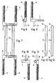
- the rod 1 comprises two threaded rods 1, 2, which are connected to one another in that the threaded rod 2 is fixedly connected in the transverse direction with a thin-walled sleeve 3 and the threaded rod 1 in the transverse direction with a rod 4, the latter in the sleeve 3 is guided appropriately and contains circumferential grooves 5.
- the rod 4 is in the sleeve 3rd initially freely movable, so that different distance settings, as indicated in Fig. 1 with solid and dash-dotted lines, can be set.
- the sleeve 3 can be deformed in places into the recesses 5 of the rod 4 with a suitable pinching tool, the jaws of which are indicated by the arrows 6, thereby ensuring the mutual adjustment of these parts in the longitudinal direction.
- FIG. 1 The shape of the components of the holder according to FIG. 1 can be seen more clearly from FIGS. 2 to 5. It can be seen that the cross-connection of the threaded rods 1 and 2 is slightly offset from the plane in which they are located, so that the threaded rods 1, 2 can be inserted into the recesses next to the mandrel projections of the spine.
- a special feature of this embodiment is that the sleeve 3 and the rod 4 can still be rotated against each other even after their positive connection. This allows the application shown in FIG. 6.
- the opposite ends of the threaded rods 1, 2 are connected with bone hooks or bone screws in a known manner at 10, 11 in such a way that they do not lie parallel to one another, but rather blunt Include angles with each other. If they are subsequently pivoted in the direction of the arrows by means of suitable tools, which is possible thanks to the rotatability of the rod 4 relative to the sleeve 3, this results in a toggle-like function by which the vertebrae 7 and 8 are distracted.
- the embodiment according to FIG. 7 comprises two holders 12, 13 equipped according to the invention with threaded rods 14 which are connected to one another by a pair of rods or tubes 15 which can be detachably attached to the holders 12, 13.
- plug pins 16 which fit into the sleeve ends 17 of the pipes or rods 15, are firmly attached to the two parts of which the holders 12, 13 each consist.
- the sleeve ends 17 and the plug pin 16 are held together by the counterforce which is exerted on the holder as a result of the bone distraction.
- the sleeve ends 17 are equipped with a nose 18 and the holders 12, 13 are provided at a corresponding point with a cutout 19 into which the nose 18 engages.
- the length of the rod-shaped connection to the two parts, from which the holders 12, 13 each consist, can be adjusted in the same way as was described with reference to FIG. 1 above.
- the versions consist of materials that have been tried and tested for such purposes.
- At least the sleeve 3 is made of a material that is plastically deformable and has the ability to maintain its deformed shape, generally of a corresponding metal.
Landscapes
- Health & Medical Sciences (AREA)
- Orthopedic Medicine & Surgery (AREA)
- Life Sciences & Earth Sciences (AREA)
- Neurology (AREA)
- Surgery (AREA)
- Heart & Thoracic Surgery (AREA)
- Engineering & Computer Science (AREA)
- Biomedical Technology (AREA)
- Nuclear Medicine, Radiotherapy & Molecular Imaging (AREA)
- Medical Informatics (AREA)
- Molecular Biology (AREA)
- Animal Behavior & Ethology (AREA)
- General Health & Medical Sciences (AREA)
- Public Health (AREA)
- Veterinary Medicine (AREA)
- Prostheses (AREA)
- Surgical Instruments (AREA)
Claims (6)
- Fixateur pour chirurgie des os, qui présente une partie en forme de tige, réglable en longueur, caractérisé en ce que la partie en forme de tige, réglable en longueur comprend un manchon (3) à paroi fine constitué d'un métal plastiquement déformable et une tige (4) s'engageant dans le manchon ayant une multiplicité d'évidements (5) disposés consécutivement dans la direction longitudinale.
- Fixateur selon la revendication 1, caractérisé en ce que les évidements (5) constituent des rainures circonférentielles.
- Fixateur selon la revendication 1, caractérisé en ce que les évidements (5) présentent des délimitations circonférentielles.
- Fixateur selon l'une des revendications 1 à 3, caractérisé en ce qu'il présente deux tiges filetées (1, 2; 14) formant un cadre en H.
- Fixateur selon l'une des revendications 1 à 4, caractérisé en ce que le manchon (3) et la tige (4) présentent chacun un dispositif d'accouplement (16, 17) en pivot d'emboîtement disposé perpendiculairement.
- Fixateur selon la revendication 5, caractérisé en ce que le dispositif d'accouplement en pivot d'emboîtement présente un dispositif d'arrêt (18, 19) s'opposant à la torsion.
Applications Claiming Priority (2)
| Application Number | Priority Date | Filing Date | Title |
|---|---|---|---|
| DE9004239U | 1990-04-11 | ||
| DE9004239U DE9004239U1 (fr) | 1990-04-11 | 1990-04-11 |
Publications (2)
| Publication Number | Publication Date |
|---|---|
| EP0451765A1 EP0451765A1 (fr) | 1991-10-16 |
| EP0451765B1 true EP0451765B1 (fr) | 1994-08-24 |
Family
ID=6852859
Family Applications (1)
| Application Number | Title | Priority Date | Filing Date |
|---|---|---|---|
| EP91105551A Expired - Lifetime EP0451765B1 (fr) | 1990-04-11 | 1991-04-08 | Fixateur pour chirurgie des os |
Country Status (3)
| Country | Link |
|---|---|
| EP (1) | EP0451765B1 (fr) |
| DE (2) | DE9004239U1 (fr) |
| ES (1) | ES2060231T3 (fr) |
Families Citing this family (3)
| Publication number | Priority date | Publication date | Assignee | Title |
|---|---|---|---|---|
| FR2709411B1 (fr) * | 1993-09-03 | 1995-11-17 | Sofamor | Pince de stabilisation d'un segment rachidien cervical. |
| US8808332B2 (en) | 2012-12-31 | 2014-08-19 | Globus Medical, Inc. | Method for stabilizing the spine |
| US7892258B2 (en) | 2008-01-14 | 2011-02-22 | Globus Medical, Inc. | Spine stabilization system and integrated rod |
Family Cites Families (4)
| Publication number | Priority date | Publication date | Assignee | Title |
|---|---|---|---|---|
| FR2289164A1 (fr) * | 1974-11-04 | 1976-05-28 | Tornier Rene | Perfectionnements aux dispositifs pour le traitement de la scoliose |
| DE3434753C2 (de) * | 1984-03-14 | 1986-12-04 | Fraunhofer-Gesellschaft zur Förderung der angewandten Forschung e.V., 8000 München | Implantat zur operativen Korrektur der seitlichen Wirbelsäulenverkrümmung |
| US4573454A (en) * | 1984-05-17 | 1986-03-04 | Hoffman Gregory A | Spinal fixation apparatus |
| FR2624720B1 (fr) * | 1987-12-21 | 1994-04-15 | Fabrication Materiel Orthopediqu | Implant pour dispositif d'osteosynthese, notamment du rachis |
-
1990
- 1990-04-11 DE DE9004239U patent/DE9004239U1/de not_active Expired - Lifetime
-
1991
- 1991-04-08 ES ES91105551T patent/ES2060231T3/es not_active Expired - Lifetime
- 1991-04-08 EP EP91105551A patent/EP0451765B1/fr not_active Expired - Lifetime
- 1991-04-08 DE DE59102601T patent/DE59102601D1/de not_active Expired - Fee Related
Also Published As
| Publication number | Publication date |
|---|---|
| DE59102601D1 (de) | 1994-09-29 |
| ES2060231T3 (es) | 1994-11-16 |
| DE9004239U1 (fr) | 1991-08-08 |
| EP0451765A1 (fr) | 1991-10-16 |
Similar Documents
| Publication | Publication Date | Title |
|---|---|---|
| EP0452451B1 (fr) | Vis pour pedicule vertebral et dispositif de correction et de maintien pourvu d'une telle vis | |
| DE69723108T2 (de) | Regulierbare osteosynthesevorrichtung für die wirbelsäule und positionierungswerkzeug | |
| DE69633302T2 (de) | Regelbare positionierungsanlage für knochen | |
| EP0153546B1 (fr) | Fixation pour immobiliser des fragments d'os | |
| DE3023942C2 (de) | Implantat zum Einsetzen zwischen Wirbelkörper der Wirbelsäule und Zange zum Einsetzen und Distrahieren desselben | |
| EP0379551B1 (fr) | Dispositif de correction et de maintien, notamment de la colonne vertebrale | |
| EP0844856B1 (fr) | Implant intervertebral et instruments pour placer l'implant intervertebral | |
| AT391266B (de) | Aeusserlich einsetzbarer minifixator | |
| DE19804765C2 (de) | Platzhalter mit einstellbarer axialer Länge | |
| DE4012622C1 (en) | Two-part metal vertebra implant - has parts locked by two toothed racks, pre-stressed by elastic cushion between both implant parts | |
| DE3941523A1 (de) | Chirurgisches gleitinstrument und verfahren zur handhabung desselben | |
| EP0328883B1 (fr) | Dispositif d'étaiement de la colonne vertébrale humaine | |
| DE102006024168A1 (de) | Mehrwandiger Platzhalter | |
| DE102015008036A1 (de) | Pedikelschraube mit Tulpe | |
| DE3942429A1 (de) | Posteriorspinalsystem | |
| DE2718515A1 (de) | Orthopaedische fixiereinrichtung | |
| DD201851A5 (de) | Handoperationstisch | |
| DE2915050A1 (de) | Vorrichtung zur behandlung von rueckgratverkruemmungen | |
| DE20320974U1 (de) | Längenverstellbares Wirbelsäulen-Implantat | |
| WO2005044117A2 (fr) | Element ressort pour un dispositif de stabilisation pour des os et procede de production de cet element ressort | |
| CH615821A5 (fr) | ||
| EP2505155A1 (fr) | Implant de colonne vertébrale pour la stabilisation et le raidissement de vertèbres d'une colonne vertébrale | |
| EP0314021A2 (fr) | Dispositif pour fixer des parties d'os | |
| EP0451765B1 (fr) | Fixateur pour chirurgie des os | |
| DE19746687A1 (de) | Vorrichtung zur externen Fixierung von gebrochenen Knochen, insbesondere der Extremitäten |
Legal Events
| Date | Code | Title | Description |
|---|---|---|---|
| PUAI | Public reference made under article 153(3) epc to a published international application that has entered the european phase |
Free format text: ORIGINAL CODE: 0009012 |
|
| AK | Designated contracting states |
Kind code of ref document: A1 Designated state(s): CH DE ES FR GB IT LI NL SE |
|
| 17P | Request for examination filed |
Effective date: 19920406 |
|
| 17Q | First examination report despatched |
Effective date: 19931110 |
|
| GRAA | (expected) grant |
Free format text: ORIGINAL CODE: 0009210 |
|
| AK | Designated contracting states |
Kind code of ref document: B1 Designated state(s): CH DE ES FR GB IT LI NL SE |
|
| REF | Corresponds to: |
Ref document number: 59102601 Country of ref document: DE Date of ref document: 19940929 |
|
| REG | Reference to a national code |
Ref country code: ES Ref legal event code: FG2A Ref document number: 2060231 Country of ref document: ES Kind code of ref document: T3 |
|
| ITF | It: translation for a ep patent filed |
Owner name: UFFICIO TECNICO ING. A. MANNUCCI |
|
| ET | Fr: translation filed | ||
| GBT | Gb: translation of ep patent filed (gb section 77(6)(a)/1977) |
Effective date: 19941124 |
|
| EAL | Se: european patent in force in sweden |
Ref document number: 91105551.5 |
|
| PLBE | No opposition filed within time limit |
Free format text: ORIGINAL CODE: 0009261 |
|
| STAA | Information on the status of an ep patent application or granted ep patent |
Free format text: STATUS: NO OPPOSITION FILED WITHIN TIME LIMIT |
|
| 26N | No opposition filed | ||
| REG | Reference to a national code |
Ref country code: GB Ref legal event code: IF02 |
|
| PGFP | Annual fee paid to national office [announced via postgrant information from national office to epo] |
Ref country code: GB Payment date: 20050331 Year of fee payment: 15 |
|
| PGFP | Annual fee paid to national office [announced via postgrant information from national office to epo] |
Ref country code: NL Payment date: 20050418 Year of fee payment: 15 |
|
| PGFP | Annual fee paid to national office [announced via postgrant information from national office to epo] |
Ref country code: FR Payment date: 20050419 Year of fee payment: 15 |
|
| PGFP | Annual fee paid to national office [announced via postgrant information from national office to epo] |
Ref country code: ES Payment date: 20050421 Year of fee payment: 15 |
|
| PGFP | Annual fee paid to national office [announced via postgrant information from national office to epo] |
Ref country code: SE Payment date: 20050422 Year of fee payment: 15 Ref country code: CH Payment date: 20050422 Year of fee payment: 15 |
|
| PGFP | Annual fee paid to national office [announced via postgrant information from national office to epo] |
Ref country code: DE Payment date: 20050621 Year of fee payment: 15 |
|
| PG25 | Lapsed in a contracting state [announced via postgrant information from national office to epo] |
Ref country code: GB Free format text: LAPSE BECAUSE OF NON-PAYMENT OF DUE FEES Effective date: 20060408 |
|
| PG25 | Lapsed in a contracting state [announced via postgrant information from national office to epo] |
Ref country code: SE Free format text: LAPSE BECAUSE OF NON-PAYMENT OF DUE FEES Effective date: 20060409 |
|
| PG25 | Lapsed in a contracting state [announced via postgrant information from national office to epo] |
Ref country code: ES Free format text: LAPSE BECAUSE OF NON-PAYMENT OF DUE FEES Effective date: 20060410 |
|
| PG25 | Lapsed in a contracting state [announced via postgrant information from national office to epo] |
Ref country code: LI Free format text: LAPSE BECAUSE OF NON-PAYMENT OF DUE FEES Effective date: 20060430 Ref country code: CH Free format text: LAPSE BECAUSE OF NON-PAYMENT OF DUE FEES Effective date: 20060430 |
|
| PGFP | Annual fee paid to national office [announced via postgrant information from national office to epo] |
Ref country code: IT Payment date: 20060430 Year of fee payment: 16 |
|
| PG25 | Lapsed in a contracting state [announced via postgrant information from national office to epo] |
Ref country code: NL Free format text: LAPSE BECAUSE OF NON-PAYMENT OF DUE FEES Effective date: 20061101 Ref country code: DE Free format text: LAPSE BECAUSE OF NON-PAYMENT OF DUE FEES Effective date: 20061101 |
|
| REG | Reference to a national code |
Ref country code: CH Ref legal event code: PL |
|
| EUG | Se: european patent has lapsed | ||
| GBPC | Gb: european patent ceased through non-payment of renewal fee |
Effective date: 20060408 |
|
| NLV4 | Nl: lapsed or anulled due to non-payment of the annual fee |
Effective date: 20061101 |
|
| REG | Reference to a national code |
Ref country code: FR Ref legal event code: ST Effective date: 20061230 |
|
| REG | Reference to a national code |
Ref country code: ES Ref legal event code: FD2A Effective date: 20060410 |
|
| PG25 | Lapsed in a contracting state [announced via postgrant information from national office to epo] |
Ref country code: FR Free format text: LAPSE BECAUSE OF NON-PAYMENT OF DUE FEES Effective date: 20060502 |
|
| PG25 | Lapsed in a contracting state [announced via postgrant information from national office to epo] |
Ref country code: IT Free format text: LAPSE BECAUSE OF NON-PAYMENT OF DUE FEES Effective date: 20070408 |