EP0451705B1 - Apparatus for and method of applying an elastic material to a flexible backing - Google Patents
Apparatus for and method of applying an elastic material to a flexible backing Download PDFInfo
- Publication number
- EP0451705B1 EP0451705B1 EP91105341A EP91105341A EP0451705B1 EP 0451705 B1 EP0451705 B1 EP 0451705B1 EP 91105341 A EP91105341 A EP 91105341A EP 91105341 A EP91105341 A EP 91105341A EP 0451705 B1 EP0451705 B1 EP 0451705B1
- Authority
- EP
- European Patent Office
- Prior art keywords
- drum
- strip
- backing
- elastic
- adhesive
- Prior art date
- Legal status (The legal status is an assumption and is not a legal conclusion. Google has not performed a legal analysis and makes no representation as to the accuracy of the status listed.)
- Expired - Lifetime
Links
Images

Classifications
-
- A—HUMAN NECESSITIES
- A61—MEDICAL OR VETERINARY SCIENCE; HYGIENE
- A61F—FILTERS IMPLANTABLE INTO BLOOD VESSELS; PROSTHESES; DEVICES PROVIDING PATENCY TO, OR PREVENTING COLLAPSING OF, TUBULAR STRUCTURES OF THE BODY, e.g. STENTS; ORTHOPAEDIC, NURSING OR CONTRACEPTIVE DEVICES; FOMENTATION; TREATMENT OR PROTECTION OF EYES OR EARS; BANDAGES, DRESSINGS OR ABSORBENT PADS; FIRST-AID KITS
- A61F13/00—Bandages or dressings; Absorbent pads
- A61F13/15—Absorbent pads, e.g. sanitary towels, swabs or tampons for external or internal application to the body; Supporting or fastening means therefor; Tampon applicators
- A61F13/15577—Apparatus or processes for manufacturing
- A61F13/15585—Apparatus or processes for manufacturing of babies' napkins, e.g. diapers
- A61F13/15593—Apparatus or processes for manufacturing of babies' napkins, e.g. diapers having elastic ribbons fixed thereto; Devices for applying the ribbons
-
- Y—GENERAL TAGGING OF NEW TECHNOLOGICAL DEVELOPMENTS; GENERAL TAGGING OF CROSS-SECTIONAL TECHNOLOGIES SPANNING OVER SEVERAL SECTIONS OF THE IPC; TECHNICAL SUBJECTS COVERED BY FORMER USPC CROSS-REFERENCE ART COLLECTIONS [XRACs] AND DIGESTS
- Y10—TECHNICAL SUBJECTS COVERED BY FORMER USPC
- Y10T—TECHNICAL SUBJECTS COVERED BY FORMER US CLASSIFICATION
- Y10T156/00—Adhesive bonding and miscellaneous chemical manufacture
- Y10T156/10—Methods of surface bonding and/or assembly therefor
- Y10T156/1002—Methods of surface bonding and/or assembly therefor with permanent bending or reshaping or surface deformation of self sustaining lamina
- Y10T156/1025—Methods of surface bonding and/or assembly therefor with permanent bending or reshaping or surface deformation of self sustaining lamina to form undulated to corrugated sheet and securing to base with parts of shaped areas out of contact
-
- Y—GENERAL TAGGING OF NEW TECHNOLOGICAL DEVELOPMENTS; GENERAL TAGGING OF CROSS-SECTIONAL TECHNOLOGIES SPANNING OVER SEVERAL SECTIONS OF THE IPC; TECHNICAL SUBJECTS COVERED BY FORMER USPC CROSS-REFERENCE ART COLLECTIONS [XRACs] AND DIGESTS
- Y10—TECHNICAL SUBJECTS COVERED BY FORMER USPC
- Y10T—TECHNICAL SUBJECTS COVERED BY FORMER US CLASSIFICATION
- Y10T156/00—Adhesive bonding and miscellaneous chemical manufacture
- Y10T156/10—Methods of surface bonding and/or assembly therefor
- Y10T156/1052—Methods of surface bonding and/or assembly therefor with cutting, punching, tearing or severing
- Y10T156/1062—Prior to assembly
- Y10T156/1075—Prior to assembly of plural laminae from single stock and assembling to each other or to additional lamina
- Y10T156/1077—Applying plural cut laminae to single face of additional lamina
-
- Y—GENERAL TAGGING OF NEW TECHNOLOGICAL DEVELOPMENTS; GENERAL TAGGING OF CROSS-SECTIONAL TECHNOLOGIES SPANNING OVER SEVERAL SECTIONS OF THE IPC; TECHNICAL SUBJECTS COVERED BY FORMER USPC CROSS-REFERENCE ART COLLECTIONS [XRACs] AND DIGESTS
- Y10—TECHNICAL SUBJECTS COVERED BY FORMER USPC
- Y10T—TECHNICAL SUBJECTS COVERED BY FORMER US CLASSIFICATION
- Y10T156/00—Adhesive bonding and miscellaneous chemical manufacture
- Y10T156/17—Surface bonding means and/or assemblymeans with work feeding or handling means
- Y10T156/1702—For plural parts or plural areas of single part
- Y10T156/1712—Indefinite or running length work
- Y10T156/1722—Means applying fluent adhesive or adhesive activator material between layers
-
- Y—GENERAL TAGGING OF NEW TECHNOLOGICAL DEVELOPMENTS; GENERAL TAGGING OF CROSS-SECTIONAL TECHNOLOGIES SPANNING OVER SEVERAL SECTIONS OF THE IPC; TECHNICAL SUBJECTS COVERED BY FORMER USPC CROSS-REFERENCE ART COLLECTIONS [XRACs] AND DIGESTS
- Y10—TECHNICAL SUBJECTS COVERED BY FORMER USPC
- Y10T—TECHNICAL SUBJECTS COVERED BY FORMER US CLASSIFICATION
- Y10T156/00—Adhesive bonding and miscellaneous chemical manufacture
- Y10T156/17—Surface bonding means and/or assemblymeans with work feeding or handling means
- Y10T156/1702—For plural parts or plural areas of single part
- Y10T156/1712—Indefinite or running length work
- Y10T156/1734—Means bringing articles into association with web
Definitions
- This invention relates to an apparatus for and method of applying an elastic strip to a flexible backing. It relates in particular to an apparatus for and method of applying elastic strips to flexible plastic backings, such as polyethylene films, to be used in catamenial devices.
- an absorbent material for example, a batt made from cellulosic fluff, that is backed with a thin plastic film.
- the backing is supposed to retain moisture in the device.
- such devices have been designed to conform to the body.
- an elastic member is often bonded to the plastic backing so as to create pleats or folds in the backing.
- the elastic is typically bonded to the flat backing while the elastic is stretched. After the elastic is secured, the elastic is released which causes the elastic to contract and gather the flat backing and the absorbent material into a curved shape that conforms to the body.
- Examples of a device and method of applying elastic to a flexible backing are illustrated in EP-A-0 154 068 describing a method and an apparatus as defined in the preambles of claims 1 and 17, and in US-A-4,397,704 issued to Frick on August 9, 1983.
- These publications teach that a flexible backing is corrugated by winding the backing onto a drum with corrugations formed in its circumference. While the drum was rotating, unstretched, adhesive-coated elastic strips were applied intermittently onto and perpendicular to the corrugations on the corrugated backing such that the elastic strips adhered only to the peaks, but not the valleys, of the corrugations.
- the flexible backing was unwound from the drum and stretched such that the corrugations were removed and the portions of the strips previously spanning the valleys contacted the backing.
- the elastic was then adhered along its length to the stretched backing by passing the backing and elastic through nip rolls. When the assembly was allowed to relax after stretching, the elastic gathered the backing.
- each piece of bonded elastic has regions of stretched and unstretched elastic between the ends of the elastic. Therefore, when the elastic strip is stretched to the extent that the flexible backing will permit, the unstretched regions correspond to those areas of the elastic that were originally adhered to the peaks of the corrugations in the unstretched state. The stretched regions correspond to those areas that spanned the valleys of the corrugations. The unstretched regions reduce the effectiveness of the elastic because they do not contribute to the gathering of the backing.
- the method of this invention involves feeding the flexible backing material onto a drum that has surface grooves parallel to the axis of the drum such that at least a portion of the flexible backing overlays the drum and the internal surface of at least one of the grooves.
- the grooves are spaced between about 5 and 25 centimeters (cm) apart on the drum, and each of the grooves has a substantially smooth internal surface with a surface length between about 3 and 24 cm.
- Each of the grooves is between approximately 2.5 and 7.5 cm wide.
- the ratio between the surface length and groove width is between about 1.3:1 and 3:1.
- the adhesive is applied to the backing such that more adhesive is applied per unit area of backing to adhere the ends of the elastic than its intermediate portion.
- At least one elastic strip is placed across the width of the one groove.
- the elastic strip is anchored at its ends to the flexible backing on the edge of the groove outside the groove so the strip spans the groove.
- the flexible backing is drawn off the drum and pulled so that the elastic is stretched to overlay the backing.
- the portion of the elastic located intermediate the anchored ends is adhered to the backing when the intermediate portion is stretched. When the elastic is allowed to relax, it gathers the flexible backing into localized pleats.
- the flexible backing is used in small absorbent devices, and the elastic allows the device to conform to the human body.
- the general object of this invention is to provide an apparatus for a method for applying an elastic material to a flexible backing.
- a more specific object of this invention is to provide an apparatus which permits elastic strips to be aligned with and fastened to a backing member.
- Another object of this invention is to provide an apparatus which utilizes a drum having a plurality of surface grooves formed therein and into which a backing material can droop.
- Still another object of this invention is to provide a simple and economical means of applying elastic strips to a flexible backing material.
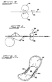
- the apparatus 10 includes a feed device 12 for feeding backing and elastic onto a looper drum 14.
- the looper drum 14 and appurtenant devices apply elastic strips to the backing in a manner described below.
- the backing is then removed in a continuous sheet from the looper drum 14 by a conveyor 16.
- the backing is then used for backing catamenial devices as shown in Fig. 7.
- Feed device 12 includes a first dispensing roll for dispensing a flexible backing sheet material 20.
- the backing sheet 20 is preferably a thin sheet of polyethylene, for example, about 0.5 to 3 millimeters (mm) thick and about 5 to 20 cm. wide.
- the backing sheet 20 is passed above apparatus 10 on a series of guide rolls 26b and 26c, and fed between a pair of motor-driven nip rolls 28a and 28b.
- the nip rolls 28a and 28b draw the backing sheet 20 from the feed roll and over the guide rolls 26b and 26c, and feed the backing sheet 20 onto the looper drum 14.
- the feed device 12 also includes a second dispensing roll 18 for dispensing an elastic strip material 24.
- the elastic strip 24 is preferably made from stretch bonded laminate (SBL), and comes in a continuous strip that is about 4 centimeters (cm) wide.
- SBL stretch bonded laminate
- the elastic material 24 is drawn across a guide roll 30 by a pair of motor-driven nip rolls 32a and 32b. As the elastic strip 24 is drawn across the guide roll 30, it is cut lengthwise by a score slitter 22 which is mounted adjacent to the roll 30 into two approximately 2 cm wide continuous parallel strips. The two strips are then fed by nip rolls 32a and 32b between a vacuum transfer drum 34 and an elastic cutter 36 described in more detail below.
- the elastic cutter 36 cuts the two parallel elastic strips simultaneously, and the vacuum transfer drum 34a transfers the two strips onto the looper drum 14.
- the looper drum 14 is a cylindrical drum that is rotated around its longitudinal axis by a motor (not shown).
- the looper drum 14 has a plurality of grooves 38 that are formed parallel to the longitudinal axis of drum and spaced equidistant from each other around the circumference of the drum about 5 to 25 cm apart.
- the looper drum 14 has vacuum suction means that operate to draw suction through the surface of the drum 14 at locations and times described below.
- the looper drum 14 is rotated clockwise when viewed from the side shown in Fig. 1.
- the backing sheet 20 is fed onto the surface of the looper drum 14 by the nip rolls 28a and 28b that are positioned at approximately the 11 o'clock position relative to the drum 14.
- a vacuum is applied to that portion of the drum 14 starting between the 11 and 12 o'clock positions, and the vacuum is ended at about the six o'clock position. No vacuum is applied to the surface of the drum 14 between the six o'clock position and the vacuum start position.
- the operation of the looper drum 14 can be understood by following one groove 38a as it rotates from the 12 o'clock position clockwise. As the backing sheet 20 is fed onto the surface of the looper drum 14, the vacuum draws a portion of the backing sheet 20 into a groove 38a at the 12 o'clock position as shown in Fig. 2.
- the vacuum is drawn at a pressure of between about 1333 and 6666 mbar (1000 and 5000 torr).
- the nip rolls 28 feed the backing sheet 20 at a rate that allows the necessary backing sheet 20 to be drawn into the groove 38a without noticeable stretching of the backing sheet 20.
- the feed rate of the nip rolls 28a and 28b is not so fast that the backing sheet material 20 between adjacent grooves 38 cannot lay smooth on the surface of the looper drum 14.
- a pressure-sensitive adhesive is sprayed from a stationary adhesive gun 40 in two spaced parallel strips, for example, in strips where the elastic will be secured as described below, that are between about 0.5 and 18 cm apart, preferably 6 cm apart.
- the adhesive is preferably a sprayable, pressure-sensitive type, for example, adhesive 70-3166 from National Starch Corporation.
- the adhesive has a shear force of between 1000 and 4000 grams as measured by an Instron machine.
- Each strip of adhesive is applied into the groove 38a and on anchor areas 42a and 42b on either side and outside of the groove 38a on the surface of the looper drum 14. The adhesive is not otherwise applied to the backing sheet 20 on the surface of the looper drum 14.
- the stationary adhesive gun 40 allows more adhesive to be applied per unit area on the anchor areas 42a and 42b than on the backing sheet 20 lining the groove 38a.
- the reason for this is that the looper drum 14 is rotated at a constant speed under the adhesive gun 40 while the adhesive is sprayed on at a constant rate. Since there is more area in the groove 38a to cover with adhesive per unit time than on the anchor areas 42a and 42b, the backing sheet 20 receives less adhesive.
- the vacuum transfer drum 34 simultaneously transfers onto the looper drum 14 two strips of elastic 44.
- the elastic strips 44 are cut from the continuous elastic strip 24 such that the two strips 44 are parallel to one another and span the groove 38a, as is shown in Fig. 3. Only one of the elastic strips 44 is shown in Fig. 3.
- Each of the elastic strips 44 is positioned such that its ends overlay the adhesive-coated anchor areas 42a and 42b.
- Each elastic strip 44 is positioned such that between about 0.3 and 2.5 cm of each end overlays the anchor areas 42a and 42b.
- the vacuum transfer drum 34 is close to the looper drum 14.
- the gap between the surfaces of the two drums 34 and 14 is about 0.5 to 3.0 times the thickness of the elastic.
- the elastic strips 44 are applied such that they pass through this gap, which compresses the ends of elastic strips 44 against the anchor areas 42a and 42b.
- This ratio of gap thickness to elastic thickness has been found to provide an initial attachment of elastic to the backing sheet 20 without compressing the backing sheet 20 and the elastic unduly to cause adhesive to ooze from between them.
- the elastic is preferably a stretch bonded laminate type, for example, from Kimberly-Clark Corp., and has a modulus of elasticity between about 80N/m2 to about 120N/m2. When the elastic is stretched 100%, it has a tension ranging between about 350 and 450 grams per inch width of the elastic.
- Nip rolls 46 and 48 are positioned at about the four o'clock and about the six o'clock positions.
- the nip roll 46 further compresses the elastic strips 44 onto the anchor areas 42a and 42b.
- the nip roll 48 isolates the nip roll 46 from the tension exerted on the backing sheet 20 by the conveyor 16. After the six o'clock position, the vacuum exerted on the groove 38a is released, and the backing sheet 20 is removed from the looper drum 14 in a manner described below.
- the grooves 38 on the looper drum 14 should have a substantially smooth internal surface.
- the "internal surface” is the area between points A and B along the surface of the groove shown in Fig. 2.
- substantially smooth is meant that there are no sharp contours that prevent the backing sheet 20 from conforming to the contours of the internal surface of the groove 38.
- the groove 38a has two flat sidewalls 50a and 50b that slope toward one another as they go deeper into the groove 38.
- the sidewalls 50a and 50b slope at an angle alpha, (see Fig. 3) between about 5 and 20 degrees as measured from a radius R drawn through the middle of the groove 38.
- the bottom ends of the sidewalls 50a and 50b are joined by a curved portion 52.
- the backing sheet 20 will slide into and conform to the groove 38. If the groove 38 were not substantially smooth, then too little backing sheet material 20 may be drawn into the grooves 38, or different amounts of material will be drawn into the several grooves 38. If too little backing sheet material 20 is drawn into the grooves 38, that affects the degree of gathering of the backing sheet material 20. If different amounts of backing sheet material 20 are drawn into the several grooves 38, that may adversely affects the positioning of the elastic as well.
- the grooves 38 also have a surface length from about 3 to 24 cm long, preferably from about 5 to 15 cm long.
- surface length is meant the length of the surface of the groove 38a between points A and B in Fig. 2.
- the grooves 38 also have a width W between points A and B of between about 2.5 and 7.5 cm., preferably between about 4 and 7 cm.
- the ratio between the surface length and groove width is between about 1.3:1 and 3:1, preferably between about 1.75:1 and 2:1.
- the elastic strips 44 are produced from the elastic material 24.
- the elastic material 24 is slit with a stationary knife 22 longitudinally into two parallel strips, each of which is about 2 cm. wide.
- the two parallel strips are spread about 5 cm apart, and fed between the nip rolls 32a and 32b.
- the nip rolls 32a and 32b are rotated stepwise at the same speed. Their speed is controlled by an optical sensor that senses the rotational speed and position of the looper drum 14.
- the speed of the nip rolls 32a and 32b are controlled such that only about 6 cm lengths of elastic are fed to the vacuum transfer drum 34 and to the cutter 36 for every groove 38 that passes the vacuum transfer drum 34.
- the vacuum transfer drum 34 has a pair of cutting mandrels 35 that are spaced 180 degrees apart on the cylindrical surface.
- the mandrels 35 contact the cutter blades 37 that protrude from the surface of cutter drum 36.
- the cutter drum 36 is driven synchronously with the vacuum transfer drum 34 so that as the approximately 6 cm lengths of elastic are fed between the vacuum transfer drum 34 and the cutter drum 36 by the nips 32a and 32b, a cutter blade 37 will contact the mandrel 35 to sever the two long strips of elastic 44 (see Figs. 1 and 3).
- the vacuum transfer drum 34 includes a vacuum device that holds the elastic strips 44 onto the surface of vacuum transfer drum 34 until the drum 34 rotates so that the elastic strips 44 are between the vacuum transfer drum 34 and the looper drum 14.
- the vacuum is then released from the elastic strips 44, and the elastic strips 44 are compressed against and adhered to the anchor areas on the backing sheet 20 as described previously.
- the vacuum transfer drum 34 is driven synchronously with the looper drum 14 so that they rotate at the same angular speed.
- the "same angular speed" means that their surfaces travel at the same velocity.
- the tension on the backing sheet 20, as it is removed from the looper drum 14, is from having to operate the conveyor 16 to remove the backing sheet 20 from the looper drum 14 at a speed 5% greater than the speed of the backing sheet 20 being fed onto the looper drum 14. It was found necessary to do this to stretch the elastic strips 44 between the anchor areas 42a and 42b so that the elastic overlays the backing sheet material 20 that was gathered into the groove 38a, (see Fig. 5).
- the stretching of the elastic begins as the backing sheet 20 is removed from the looper drum 14 (see Fig. 4) and has to be completed before the backing sheet 20 is drawn through a pair of nip rolls 54 and 56 (see Fig. 5) in the conveyor 16.
- the nip rolls 54 and 56 compress the stretched elastic against the backing sheet 20 such that the adhesive applied between the anchor areas 42a and 42b, for example, the adhesive applied to the backing sheet 20 that was once in the groove 38a, can adhere the elastic to the backing sheet 20 between the anchor areas.
- the adhesive is applied with an adhesive gun 58 (see Fig. 6) across the entire surface of the backing sheet 20 on which the elastic strips 44 are adhered.
- absorbent pads 60 are spaced along a conveyor (not shown) and fed by the conveyor onto a continuous sheet of cover material 62 which is moving at the same speed as the conveyor.
- the backing material 20, which is still under tension to keep the elastic strips 44 stretched, is fed at the same speed as the cover material 62 through a pair of nip rolls 64 and 66.
- the adhesive previously sprayed onto the backing sheet 20 adheres the absorbent pads 60 onto the backing sheet 20 and adheres the cover material 62 to the backing sheet 20 around the perimeters of the absorbent pads 60. It should be noted that the absorbent pads 60 are narrower than the width of the backing sheet 20 and the cover sheet 62.
- a finished catamenial pad 68 which has been die cut from the web of material passed through the nip rolls 64 and 66.
- Each finished pad 68 has two parallel elastic strips 44 that gather the otherwise planar product into a curved absorbent pad 68.
- the elastic strips 44 form part of the perimeter of the catamenial pads 68, and are centered along the middle edges of the pad with the absorbent pad 60 positioned therebetween.
- the backing sheet 20 is adhered about its perimeter to the cover sheet 62.
- the cover sheet 62 is made from a spunbonded material that allows moisture to flow easily through, so that it can be absorbed by the absorbent pad 60.
- the catamenial pad 68 is constructed otherwise as taught in U.S. patent 4,770,657 issued to Ellis et al. on September 13, 1988.
Applications Claiming Priority (2)
| Application Number | Priority Date | Filing Date | Title |
|---|---|---|---|
| US07/505,954 US5171388A (en) | 1990-04-06 | 1990-04-06 | Apparatus for and method of applying an elastic material to a flexible backing |
| US505954 | 1990-04-06 |
Publications (2)
| Publication Number | Publication Date |
|---|---|
| EP0451705A1 EP0451705A1 (en) | 1991-10-16 |
| EP0451705B1 true EP0451705B1 (en) | 1994-08-03 |
Family
ID=24012567
Family Applications (1)
| Application Number | Title | Priority Date | Filing Date |
|---|---|---|---|
| EP91105341A Expired - Lifetime EP0451705B1 (en) | 1990-04-06 | 1991-04-04 | Apparatus for and method of applying an elastic material to a flexible backing |
Country Status (11)
| Country | Link |
|---|---|
| US (1) | US5171388A (pt) |
| EP (1) | EP0451705B1 (pt) |
| JP (1) | JP3279584B2 (pt) |
| KR (1) | KR0151593B1 (pt) |
| AU (1) | AU638819B2 (pt) |
| BR (1) | BR9101400A (pt) |
| CA (1) | CA2019456C (pt) |
| DE (1) | DE69103187T2 (pt) |
| MX (1) | MX173193B (pt) |
| MY (1) | MY108562A (pt) |
| ZA (1) | ZA912548B (pt) |
Families Citing this family (45)
| Publication number | Priority date | Publication date | Assignee | Title |
|---|---|---|---|---|
| US6004253A (en) * | 1995-05-17 | 1999-12-21 | 3M Innovative Properties Company | Medical adhesive bandage manufacturing |
| BR9608816A (pt) * | 1995-05-17 | 1999-06-15 | Minnesota Mining & Mfg | Processo de fabricação de uma bandagem adesiva médica |
| DE19522743C2 (de) * | 1995-05-29 | 1998-10-08 | Hyga Produktion Gmbh & Co Kg | Verfahren und Vorrichtung zur Herstellung von Windeln mit mindestens einem dehnungselastischen Bereich |
| ES2126489B1 (es) * | 1996-06-12 | 1999-11-16 | Ringo Styl S L | Procedimiento para la obtencion de un producto formado por un materialde base y materiales discontinuos y utilizacion de una maquina continua de vulcanizar para la realizacion de dicho procedimiento. |
| US5755902A (en) * | 1996-12-05 | 1998-05-26 | Kimberly Clark Corporation | Method and apparatus for producing a composite web having transverse stretch |
| EP0974323A1 (en) * | 1998-07-22 | 2000-01-26 | The Procter & Gamble Company | Apparatus for transporting a continuous web, and for manipulating the web |
| US6620276B1 (en) | 1998-07-22 | 2003-09-16 | The Procter & Gamble Company | Apparatus for transporting a continuous web, and for manipulating the web |
| US6197138B1 (en) * | 1998-12-29 | 2001-03-06 | Kimberly-Clark Worldwide, Inc. | Machine and process for placing and bonding elastic members in a relaxed state to a moving substrate web |
| US6569139B1 (en) | 2000-06-22 | 2003-05-27 | Kimberly-Clark Worldwide, Inc. | Disposable absorbent underpants for containing body fluid |
| US6440246B1 (en) | 2000-08-15 | 2002-08-27 | Kimberly-Clark Worldwide, Inc. | Method of applying curved leg elastics using rotating disks |
| US6585841B1 (en) * | 2000-08-15 | 2003-07-01 | Kimberly-Clark Worldwide, Inc. | Method of optimizing spacing between elastic members in applying leg elastics |
| US6635041B1 (en) | 2000-08-15 | 2003-10-21 | Kimberly-Clark Worldwide, Inc. | Absorbent garment with asymmetrical leg elastic tension |
| US6569275B1 (en) | 2000-08-15 | 2003-05-27 | Kimberly-Clark Worldwide, Inc. | Method of optimizing tension in applying leg elastics |
| US6652504B1 (en) | 2000-08-15 | 2003-11-25 | Kimberly-Clark Worldwide, Inc. | Pant-like absorbent garments having curved leak guard flaps |
| US6613033B1 (en) | 2000-08-15 | 2003-09-02 | Kimberly-Clark Worldwide, Inc. | Pant-like absorbent garments having curved leg cuffs |
| US6540857B1 (en) | 2000-08-15 | 2003-04-01 | Kimberly-Clark Worldwide, Inc. | Method of applying curved leg elastics using curved pucks |
| US6689115B1 (en) | 2000-08-15 | 2004-02-10 | Kimberly-Clark Worldwide, Inc. | Absorbent garment with asymmetrical leg elastic spacing |
| US6375769B1 (en) | 2000-08-15 | 2002-04-23 | Kimberly-Clark Worldwide, Inc. | Method of applying curved leg elastics using pucks with curved surfaces |
| US6881205B2 (en) * | 2000-10-27 | 2005-04-19 | Kimberly-Clark Worldwide, Inc. | Independence of components in absorbent articles |
| US6969378B1 (en) | 2000-10-27 | 2005-11-29 | Kimberly-Clark Worldwide, Inc. | Biaxial stretch garment |
| US7628778B2 (en) | 2000-10-27 | 2009-12-08 | Kimberly-Clark Worldwide, Inc. | Absorbent article with self-forming seals |
| US6914018B1 (en) | 2000-10-27 | 2005-07-05 | Kimberly-Clark Worldwide, Inc. | Biaxial stretch, breathable laminate with cloth-like aesthetics and method for making same |
| US6702800B1 (en) | 2000-10-27 | 2004-03-09 | Kimberly-Clark Worldwide, Inc. | Absorbent garment with transverse and longitudinal stretch |
| US6869424B1 (en) | 2000-10-27 | 2005-03-22 | Kimberly-Clark Worldwide, Inc. | Stretchable absorbent garment with non-stretchable liner |
| US6982231B1 (en) | 2000-10-27 | 2006-01-03 | Kimberly-Clark Worldwide, Inc. | Elastomeric, breathable laminate with enhanced breathability upon extension |
| US7608069B2 (en) | 2000-10-27 | 2009-10-27 | Kimberly-Clark Worldwide, Inc. | Absorbent article with captured leg elastics |
| JP3798298B2 (ja) * | 2000-12-01 | 2006-07-19 | 株式会社瑞光 | 回転装置、着用物品の搬送方法およびウェブの搬送方法 |
| JP2003102770A (ja) * | 2001-09-28 | 2003-04-08 | Johnson & Johnson Kk | シール装置 |
| US20030116257A1 (en) * | 2001-12-20 | 2003-06-26 | Kimberly-Clark Worldwide, Inc. | Apparatus and method for applying an elongate member to a substrate |
| US6890630B2 (en) * | 2001-12-20 | 2005-05-10 | Kimberly-Clark Worldwide, Inc. | Elastic composites for garments |
| US6706135B2 (en) | 2001-12-21 | 2004-03-16 | Kimberly-Clark Worldwide, Inc. | Process for temporarily stabilizing an extensible web |
| US7086095B2 (en) * | 2002-11-21 | 2006-08-08 | Kimberly-Clark Worldwide, Inc. | Boxer-style absorbent underpant and method of making same |
| US6984279B2 (en) | 2002-11-25 | 2006-01-10 | Kimberly-Clark Worldwide, Inc. | Process to make boxer shorts with an absorbent core |
| US20040107481A1 (en) * | 2002-12-09 | 2004-06-10 | Mortell Heather Schenck | Process to make boxer shorts having a contracted crotch region |
| US8361049B2 (en) | 2002-12-09 | 2013-01-29 | Kimberly-Clark Worldwide, Inc. | Boxer shorts and process of making boxer shorts with expandable material |
| US8147642B2 (en) | 2002-12-09 | 2012-04-03 | Kimberly-Clark Worldwide, Inc. | Process of making boxer shorts from a web |
| US8176573B2 (en) | 2002-12-09 | 2012-05-15 | Kimberly-Clark Worldwide, Inc. | Boxer shorts and process of making boxer shorts from one or more webs |
| US9700079B2 (en) | 2002-12-09 | 2017-07-11 | Kimberly-Clark Worldwide, Inc. | Process of making boxer shorts from a web with various leg opening shapes |
| US8282618B2 (en) | 2002-12-11 | 2012-10-09 | Kimberly-Clark Worldwide, Inc. | Disposable boxer brief |
| WO2008141658A1 (en) * | 2007-05-18 | 2008-11-27 | Concepts For Success-C4S E.K. | Process for the manufacturing of articles comprising a flipped leg hoop |
| US8171972B2 (en) | 2009-01-30 | 2012-05-08 | The Procter & Gamble Company | Strip guide for high-speed continuous application of a strip material to a moving sheet-like substrate material at laterally shifting locations |
| US8182627B2 (en) | 2009-01-30 | 2012-05-22 | The Procter & Gamble Company | Method for high-speed continuous application of a strip material to a substrate along an application path on the substrate |
| EP2866753A1 (en) | 2012-06-29 | 2015-05-06 | The Procter & Gamble Company | System and method for high-speed continuous application of a strip material to a moving sheet-like substrate material |
| CN110636823A (zh) | 2017-05-17 | 2019-12-31 | 贝瑞全球有限公司 | 弹性非织造物层压方法和设备 |
| WO2023164588A2 (en) * | 2022-02-28 | 2023-08-31 | Curt G. Joa, Inc. | Method and apparatus for forming an absorbent core with a pleated outer wrap |
Family Cites Families (21)
| Publication number | Priority date | Publication date | Assignee | Title |
|---|---|---|---|---|
| US3860003B2 (en) * | 1973-11-21 | 1990-06-19 | Contractable side portions for disposable diaper | |
| US3951150A (en) * | 1974-10-31 | 1976-04-20 | Colgate-Palmolive Company | Diaper with elastic waist means |
| US4543099A (en) * | 1978-12-06 | 1985-09-24 | H. B. Fuller Company | Method for imparting elastic properties to a flexible substrate |
| US4227952A (en) * | 1979-04-16 | 1980-10-14 | Sabee Products, Inc. | Method and apparatus for making diapers with elastic bands |
| US4285747A (en) * | 1979-10-18 | 1981-08-25 | Johnson & Johnson Baby Products Company | Method for manufacturing a product having elastic means disposed in the transverse direction |
| US4240866A (en) * | 1979-10-18 | 1980-12-23 | Johnson & Johnson Baby Products Company | Apparatus for manufacturing a product having elastic means disposed in the transverse direction |
| DE3016197A1 (de) * | 1980-04-26 | 1981-11-05 | Winkler & Dünnebier, Maschinenfabrik und Eisengießerei GmbH & Co KG, 5450 Neuwied | Verfahren und vorrichtung zum abschnittsweisen aufbringen elastischer streifen auf eine materialbahn zur herstellung von hoeschenwindeln o.dgl. |
| US4397704A (en) * | 1980-10-20 | 1983-08-09 | Kimberly-Clark Corporation | Method and apparatus for applying discrete lengths of elastic strip material to a continuously moving web |
| JPS57182423A (en) * | 1981-05-08 | 1982-11-10 | Mitsubishi Heavy Ind Ltd | Pasting device |
| DE3269790D1 (en) * | 1981-05-26 | 1986-04-17 | Joa Curt G Inc | Diaper, especially panty diaper, and method for its manufacture |
| US4417935A (en) * | 1981-10-13 | 1983-11-29 | Paper Converting Machine Company | Method of diaper manufacture |
| US4488923A (en) * | 1981-11-27 | 1984-12-18 | Personal Products Company | Method for producing a fabric having unsecured elastic in areas intermittently disposed along an edge thereof |
| US4417938A (en) * | 1981-11-30 | 1983-11-29 | Kimberly-Clark Corporation | Producing an elasticized garment utilizing an articulated conveyor |
| US4498944A (en) * | 1982-01-18 | 1985-02-12 | Kimberly-Clark Corporation | Method and apparatus for producing an elasticized garment by tucking a portion of the diaper web during bonding of elastic to the untucked portions of the web |
| US4425173A (en) * | 1982-07-19 | 1984-01-10 | Kimberly-Clark Corporation | Apparatus and method for producing an elasticized garment |
| US4618384A (en) * | 1983-09-09 | 1986-10-21 | Sabee Reinhardt N | Method for applying an elastic band to diapers |
| US4543154A (en) * | 1983-11-04 | 1985-09-24 | The Procter & Gamble Company | Method for severing a laminated web containing a dimensionally heat unstable layer to produce non-linear shirred edges |
| US4563185A (en) * | 1983-11-04 | 1986-01-07 | The Procter & Gamble Company | Disposable diaper having elasticized waistband with non-linear severed edge |
| DE3347294C1 (de) * | 1983-12-28 | 1985-07-18 | Vereinigte Papierwerke Schickedanz & Co, 8500 Nürnberg | Verfahren und Vorrichtung zum Herstellen von Höschenwindeln |
| US4574022A (en) * | 1984-03-05 | 1986-03-04 | H. B. Fuller Company | Apparatus and method for transferring and applying material |
| JP2609252B2 (ja) * | 1987-08-18 | 1997-05-14 | ユニ・チャーム 株式会社 | 移動ウエブへの弾性バンド貼着装置 |
-
1990
- 1990-04-06 US US07/505,954 patent/US5171388A/en not_active Expired - Lifetime
- 1990-06-20 CA CA002019456A patent/CA2019456C/en not_active Expired - Fee Related
-
1991
- 1991-04-04 DE DE69103187T patent/DE69103187T2/de not_active Expired - Fee Related
- 1991-04-04 EP EP91105341A patent/EP0451705B1/en not_active Expired - Lifetime
- 1991-04-05 MX MX025240A patent/MX173193B/es unknown
- 1991-04-05 MY MYPI91000571A patent/MY108562A/en unknown
- 1991-04-05 ZA ZA912548A patent/ZA912548B/xx unknown
- 1991-04-05 JP JP07310691A patent/JP3279584B2/ja not_active Expired - Fee Related
- 1991-04-05 AU AU74192/91A patent/AU638819B2/en not_active Ceased
- 1991-04-06 KR KR1019910005535A patent/KR0151593B1/ko not_active IP Right Cessation
- 1991-04-08 BR BR919101400A patent/BR9101400A/pt not_active IP Right Cessation
Also Published As
| Publication number | Publication date |
|---|---|
| MX173193B (es) | 1994-02-07 |
| US5171388A (en) | 1992-12-15 |
| JPH07113065A (ja) | 1995-05-02 |
| KR910018003A (ko) | 1991-11-30 |
| AU7419291A (en) | 1991-10-10 |
| ZA912548B (en) | 1992-01-29 |
| BR9101400A (pt) | 1991-11-26 |
| DE69103187D1 (de) | 1994-09-08 |
| CA2019456A1 (en) | 1991-10-06 |
| JP3279584B2 (ja) | 2002-04-30 |
| CA2019456C (en) | 2002-10-15 |
| MY108562A (en) | 1996-10-31 |
| EP0451705A1 (en) | 1991-10-16 |
| AU638819B2 (en) | 1993-07-08 |
| KR0151593B1 (ko) | 1998-10-01 |
| DE69103187T2 (de) | 1994-12-08 |
Similar Documents
| Publication | Publication Date | Title |
|---|---|---|
| EP0451705B1 (en) | Apparatus for and method of applying an elastic material to a flexible backing | |
| US4908089A (en) | Apparatus for making an elasticized unit | |
| US5296080A (en) | Apparatus for applying an elastic waistband to a disposable diaper | |
| US4285747A (en) | Method for manufacturing a product having elastic means disposed in the transverse direction | |
| US4106974A (en) | Flying splice apparatus | |
| US4925520A (en) | Apparatus for applying an elastic waistband transversely of a longitudinally moving web | |
| US6264784B1 (en) | Absorbent article with attached tabs and method and apparatus for making same | |
| EP0573586B1 (en) | Improved method and apparatus for incrementally stretching a zero strain stretch laminate web to impart elasticity thereto | |
| EP0219114B1 (en) | Applicator for applying two or more tapes to a moving web | |
| US4582550A (en) | Method of making an elasticized garment | |
| EP0706362B1 (en) | Method and apparatus for attaching a fastener to a profiled absorbent article | |
| JPS59112010A (ja) | 使い捨て衛生物品に弾性部材を取り付ける方法 | |
| US4240866A (en) | Apparatus for manufacturing a product having elastic means disposed in the transverse direction | |
| KR830006945A (ko) | 연속 이동 직물에 일정 길이의 탄성 스트립 재료를 부착시키는 방법 및 장치 | |
| EP0767643B1 (en) | A machine for manufacturing adhesive dressings having the adsorbing compress completely surrounded by the adhesive support | |
| US4488923A (en) | Method for producing a fabric having unsecured elastic in areas intermittently disposed along an edge thereof | |
| EP0091316B1 (en) | Apparatus for attaching an elastic member to a disposable diaper | |
| CA1125163A (en) | Method and apparatus for cutting plastic film windows for cartons | |
| EP0443244A1 (en) | Method and apparatus for applying an elastic waistband to a disposable diaper | |
| US5102486A (en) | Loop applying assembly | |
| US5008961A (en) | Sanitary head covering and method of manufacture | |
| EP1164997A1 (en) | A method of producing an adhesive surface protective sheet that includes a gripping tab | |
| JPS6087040A (ja) | 弾性バンドを衛生物品に取付ける方法 | |
| JPH0229334B2 (pt) | ||
| JPH0156162B2 (pt) |
Legal Events
| Date | Code | Title | Description |
|---|---|---|---|
| PUAI | Public reference made under article 153(3) epc to a published international application that has entered the european phase |
Free format text: ORIGINAL CODE: 0009012 |
|
| AK | Designated contracting states |
Kind code of ref document: A1 Designated state(s): BE CH DE FR GB IT LI LU NL |
|
| 17P | Request for examination filed |
Effective date: 19920214 |
|
| 17Q | First examination report despatched |
Effective date: 19930714 |
|
| GRAA | (expected) grant |
Free format text: ORIGINAL CODE: 0009210 |
|
| AK | Designated contracting states |
Kind code of ref document: B1 Designated state(s): BE CH DE FR GB IT LI LU NL |
|
| PG25 | Lapsed in a contracting state [announced via postgrant information from national office to epo] |
Ref country code: LI Effective date: 19940803 Ref country code: CH Effective date: 19940803 |
|
| REF | Corresponds to: |
Ref document number: 69103187 Country of ref document: DE Date of ref document: 19940908 |
|
| ITF | It: translation for a ep patent filed |
Owner name: DE DOMINICIS & MAYER S.R.L. |
|
| REG | Reference to a national code |
Ref country code: CH Ref legal event code: PL |
|
| ET | Fr: translation filed | ||
| PG25 | Lapsed in a contracting state [announced via postgrant information from national office to epo] |
Ref country code: LU Free format text: LAPSE BECAUSE OF NON-PAYMENT OF DUE FEES Effective date: 19950430 |
|
| PLBE | No opposition filed within time limit |
Free format text: ORIGINAL CODE: 0009261 |
|
| STAA | Information on the status of an ep patent application or granted ep patent |
Free format text: STATUS: NO OPPOSITION FILED WITHIN TIME LIMIT |
|
| 26N | No opposition filed | ||
| REG | Reference to a national code |
Ref country code: FR Ref legal event code: CA Ref country code: FR Ref legal event code: TP Ref country code: FR Ref legal event code: CD |
|
| REG | Reference to a national code |
Ref country code: FR Ref legal event code: RM |
|
| REG | Reference to a national code |
Ref country code: FR Ref legal event code: TP |
|
| NLS | Nl: assignments of ep-patents |
Owner name: KIMBERLY-CLARK WORLDWIDE, INC. |
|
| REG | Reference to a national code |
Ref country code: GB Ref legal event code: 732E |
|
| PGFP | Annual fee paid to national office [announced via postgrant information from national office to epo] |
Ref country code: NL Payment date: 20000320 Year of fee payment: 10 |
|
| PGFP | Annual fee paid to national office [announced via postgrant information from national office to epo] |
Ref country code: BE Payment date: 20000512 Year of fee payment: 10 |
|
| PG25 | Lapsed in a contracting state [announced via postgrant information from national office to epo] |
Ref country code: BE Free format text: LAPSE BECAUSE OF NON-PAYMENT OF DUE FEES Effective date: 20010430 |
|
| BERE | Be: lapsed |
Owner name: KIMBERLY-CLARK WORLDWIDE INC. Effective date: 20010430 |
|
| PG25 | Lapsed in a contracting state [announced via postgrant information from national office to epo] |
Ref country code: NL Free format text: LAPSE BECAUSE OF NON-PAYMENT OF DUE FEES Effective date: 20011101 |
|
| REG | Reference to a national code |
Ref country code: GB Ref legal event code: IF02 |
|
| NLV4 | Nl: lapsed or anulled due to non-payment of the annual fee |
Effective date: 20011101 |
|
| PGFP | Annual fee paid to national office [announced via postgrant information from national office to epo] |
Ref country code: GB Payment date: 20060314 Year of fee payment: 16 |
|
| PGFP | Annual fee paid to national office [announced via postgrant information from national office to epo] |
Ref country code: FR Payment date: 20060403 Year of fee payment: 16 |
|
| PGFP | Annual fee paid to national office [announced via postgrant information from national office to epo] |
Ref country code: DE Payment date: 20060428 Year of fee payment: 16 |
|
| PGFP | Annual fee paid to national office [announced via postgrant information from national office to epo] |
Ref country code: IT Payment date: 20060430 Year of fee payment: 16 |
|
| GBPC | Gb: european patent ceased through non-payment of renewal fee |
Effective date: 20070404 |
|
| PG25 | Lapsed in a contracting state [announced via postgrant information from national office to epo] |
Ref country code: DE Free format text: LAPSE BECAUSE OF NON-PAYMENT OF DUE FEES Effective date: 20071101 |
|
| PG25 | Lapsed in a contracting state [announced via postgrant information from national office to epo] |
Ref country code: GB Free format text: LAPSE BECAUSE OF NON-PAYMENT OF DUE FEES Effective date: 20070404 |
|
| PG25 | Lapsed in a contracting state [announced via postgrant information from national office to epo] |
Ref country code: FR Free format text: LAPSE BECAUSE OF NON-PAYMENT OF DUE FEES Effective date: 20070430 |
|
| PG25 | Lapsed in a contracting state [announced via postgrant information from national office to epo] |
Ref country code: IT Free format text: LAPSE BECAUSE OF NON-PAYMENT OF DUE FEES Effective date: 20070404 |