EP0451478B1 - Headlight for motor-vehicles - Google Patents
Headlight for motor-vehicles Download PDFInfo
- Publication number
- EP0451478B1 EP0451478B1 EP91102893A EP91102893A EP0451478B1 EP 0451478 B1 EP0451478 B1 EP 0451478B1 EP 91102893 A EP91102893 A EP 91102893A EP 91102893 A EP91102893 A EP 91102893A EP 0451478 B1 EP0451478 B1 EP 0451478B1
- Authority
- EP
- European Patent Office
- Prior art keywords
- washer
- wall section
- elongated hole
- pot
- wall
- Prior art date
- Legal status (The legal status is an assumption and is not a legal conclusion. Google has not performed a legal analysis and makes no representation as to the accuracy of the status listed.)
- Expired - Lifetime
Links
- 239000002184 metal Substances 0.000 claims abstract description 4
- 238000005452 bending Methods 0.000 claims description 7
- 238000007373 indentation Methods 0.000 claims 7
- 238000004080 punching Methods 0.000 claims 1
- 241001484259 Lacuna Species 0.000 abstract 1
- 239000000463 material Substances 0.000 description 2
- 241000139306 Platt Species 0.000 description 1
- 239000011521 glass Substances 0.000 description 1
- 125000006850 spacer group Chemical group 0.000 description 1
Images


Classifications
-
- F—MECHANICAL ENGINEERING; LIGHTING; HEATING; WEAPONS; BLASTING
- F16—ENGINEERING ELEMENTS AND UNITS; GENERAL MEASURES FOR PRODUCING AND MAINTAINING EFFECTIVE FUNCTIONING OF MACHINES OR INSTALLATIONS; THERMAL INSULATION IN GENERAL
- F16B—DEVICES FOR FASTENING OR SECURING CONSTRUCTIONAL ELEMENTS OR MACHINE PARTS TOGETHER, e.g. NAILS, BOLTS, CIRCLIPS, CLAMPS, CLIPS OR WEDGES; JOINTS OR JOINTING
- F16B43/00—Washers or equivalent devices; Other devices for supporting bolt-heads or nuts
Definitions
- Such lights are known from practice, of which in the figure 1 to 3 of the drawing, the wall section having the fastening opening is shown with the washer attached to it.
- the washer is securely connected to the support element and it is therefore not possible to fasten the support element to the body part without the washer.
- the openings of the support element with openings of the body part are brought into a position one above the other. So that this is also possible with the large tolerance ranges customary in the vehicle body and, moreover, the lamp can also be aligned with the body part, openings in the washers are designed as an elongated hole.
- the support element In the aligned position of the lamp, the support element is pressed with the wall sections against the body part by means of screw bolts which are inserted through the overlapping openings.
- the bolt is mounted with a precisely determined torque, since with a larger torque the pressure of the washer on the wall section can be so great that the wall thickness of the wall section in the area of the washer is compressed by cold flow of the material and thus the connection between the support element and the body part is no longer sufficiently stable. The connection is no longer stable even if the bolt is installed with too little torque.
- the size of the torque does not have to be observed exactly, but then the washer must be made thicker so that it is not deformed by the great pressure of the head of the screw bolt or the nuts.
- the object of the invention is to improve the lamp described in the preamble in such a way that a washer of the usual size can be used and still during the assembly of the support element which can be fixed by a screw bolt on the body part, the cold flow resulting from the pressure of the washer on the wall section Wall section in its size can be predetermined without taking into account the magnitude of the torque.
- Such a stable connection is particularly advantageous in the case of headlights for motor vehicles which have a Represent special design of luminaires, since they z. B. because of the often made of glass lens and the metal reflector are very heavy.
- the stable connection enables vibration-free attachment of the headlight to the body part. This is particularly important with dimmed headlights so that oncoming traffic is not dazzled.
- the elongated hole is made smaller than the bottom surface of the cup-shaped depression.
- the washer is made more stable in the region of the end face of its side wall against possible deformation when the support element is fastened to the body.
- a further advantage is if the washer has two edge regions, each bent by a bending line toward the cup-shaped depression, which form the curvature of the washer with the section running between them.
- Such a solution is very simple and can be manufactured very inexpensively.
- the bending lines can either run perpendicular or parallel to the longitudinal extension of the elongated hole. It is also expedient if the bending lines run in the vicinity of the edge of the cup-shaped depression. This makes the washer as small as possible in its external dimensions.
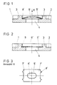
- the wall section (1) shown in FIG. 1 and FIG. 2 of a plastic support element for a lamp for vehicles has between two ribs (3) formed on the side surface (2) of the wall section (1) the fastening opening (4) and that on the side surface (2) put on washer (5).
- the washer (5) placed on the wall section (1) in FIG. 1 has a curved shape, the concave side of which faces the wall section (1).
- the washer as can be seen from Figure 3, Rectangular and has the elongated hole (6) as the central opening. On the edge regions (7) running transversely to the longitudinal extent of the elongated hole (6), tooth-shaped projections (8) directed outwards are cut free.
- the washer is pressed flat and lies against the edge region of the fastening opening (4).
- the toothed projections (8) are pressed into the facing sections (9) of the ribs (3) as a result of the extension of the washer, which the washer has experienced through the flattening.
- the washer (5) has the deep-drawn depression (10) centrally.
- the elongated hole (6) is punched out of the bottom surface of the depression (10) and is slightly smaller than the bottom surface.
- the washer (5) obtains the curved shape through the edge regions (7) which are bent around the bending lines (11) towards the cup-shaped depression (10) and from which the tooth-shaped projections (8) are cut free.
- the side wall (12) of the recess (10) extends into the fastening opening (4).
- the circumferential side wall (12) of the recess (10) is made somewhat shorter than the wall section (1) is thick.
- the nut must be tightened with such a large torque that the head of the bolt presses the circumferential edge region of the washer with such force against the wall section (1) that it is pressed together by cold flow until the washer (5) with it End face (17) of the side wall (12) is pressed against the body part (15).
- the washer on the one hand contributes to the wall section (1) being compressed to a predeterminable extent and thus being in contact with the body part with sufficient pressure, and on the other hand the washer increases the stable connection between the support element and the body part ( 15) because it rests with its end face (17) on the body part (15) and engages with the toothed projections (8) in the ribs (3) by clamping.
Landscapes
- Engineering & Computer Science (AREA)
- General Engineering & Computer Science (AREA)
- Mechanical Engineering (AREA)
- Non-Portable Lighting Devices Or Systems Thereof (AREA)
- Lighting Device Outwards From Vehicle And Optical Signal (AREA)
- Connection Of Plates (AREA)
- Fittings On The Vehicle Exterior For Carrying Loads, And Devices For Holding Or Mounting Articles (AREA)
- Luminescent Compositions (AREA)
- Vehicle Waterproofing, Decoration, And Sanitation Devices (AREA)
- Arrangements Of Lighting Devices For Vehicle Interiors, Mounting And Supporting Thereof, Circuits Therefore (AREA)
Abstract
Description
Die Erfindung bezieht sich auf eine Leuchte für Fahrzeuge, welche mit ihrem aus Kunststoff bestehenden Tragelement an einem Karosserieteil festsetzbar ist, mit folgenden Merkmalen:
- das Tragelement weist Wandungsabschnitte mit einer eingebrachten Befestigungsöffnung auf,
- auf einer Seitenfläche des Wandungsabschnitts ist eine aus Blech herausgestanzte Unterlegscheibe befestigt, welche
- ein ausgestanztes Langloch aufweist, welches die Öffnung in dem Wandungsabschnitt überlagert und kleiner als diese ist,
- vor ihrer Montage eine gewölbte Form aufweist und bei ihrer Montage mit der konkaven Seite auf dem Wandungsabschnitt aufgesetzt ist und an dem Wandungsabschnitt platt anliegend gedrückt ist,
- durch ihre Streckung mit zwei gegenüberliegenden Randbereichen in sich zugewandte Abschnitte der Seitenfläche des Wandungsabschnittes eingreift.
- the support element has wall sections with an introduced fastening opening,
- on a side surface of the wall section, a washer punched out of sheet metal is fastened, which
- has a punched-out elongated hole which overlaps the opening in the wall section and is smaller than this,
- has an arched shape prior to its assembly and is placed with its concave side on the wall section during assembly and is pressed flat against the wall section,
- engages in its mutually facing sections of the side surface of the wall section by its extension with two opposite edge regions.
Solche Leuchten sind aus der Praxis bekannt, von denen in der Figur 1 bis 3 der Zeichnung der die Befestigungsöffnung aufweisende Wandungsabschnitt mit der an ihm befestigten Unterlegscheibe dargestellt ist. Dadurch ist die Unterlegscheibe verliersicher mit dem Tragelement verbunden und es ist somit nicht möglich, das Tragelement ohne die Unterlegscheibe an dem Karosserieteil zu befestigen. Um die Leuchte an dem Karosserieteil befestigen zu können, müssen in einem ersten Montageschritt die Öffnungen des Tragelements mit Öffnungen des Karosserieteils in eine übereinanderliegende Lage gebracht werden. Damit dies auch bei den bei der Fahrzeugkarosserie üblichen großen Toleranzbereichen möglich ist und darüber hinaus auch die Leuchte zu dem Karosserieteil ausgerichtet werden kann, sind Öffnungen in Unterlegscheiben als Langloch ausgeführt. In der ausgerichteten Lage der Leuchte wird das Tragelement durch Schraubenbolzen, welche durch die sich überlagernden Öffnungen hindurchgesteckt sind, mit dem Wandungsabschnitten gegen das Karosserieteil gepreßt. Hierbei ist es jedoch notwendig, daß der Schraubenbolzen mit einem genau ermittelten Drehmoment montiert wird, da bei einem größeren Drehmoment der Druck der Unterlegscheibe auf den Wandungsabschnitt so groß sein kann, daß durch Kaltfluß des Werkstoffes die Wandstärke des Wandungsabschnitts im Bereich der Unterlegscheibe zusammengedrückt wird und somit die Verbindung zwischen dem Tragelement und dem Karosserieteil nicht mehr ausreichend stabil ist. Die Stabilität der Verbindung ist auch dann nicht mehr gegeben, wenn der Schraubenbolzen mit einem zu kleinen Drehmoment montiert ist. Bei größeren Unterlegscheiben muß zwar nicht die Größe des Drehmoments genau eingehalten werden, jedoch muß dann die Unterlegscheibe dicker ausgeführt sein, damit sie durch den großen Druck des Kopfes des Schraubenbolzens oder der Muttern nicht deformiert wird. Außerdem ist es oftmals nicht möglich, größere Unterlegscheiben wegen den oft engen Platzverhältnissen in der Karosserie zu verwenden.Such lights are known from practice, of which in the figure 1 to 3 of the drawing, the wall section having the fastening opening is shown with the washer attached to it. As a result, the washer is securely connected to the support element and it is therefore not possible to fasten the support element to the body part without the washer. In order to be able to attach the lamp to the body part, in a first assembly step, the openings of the support element with openings of the body part are brought into a position one above the other. So that this is also possible with the large tolerance ranges customary in the vehicle body and, moreover, the lamp can also be aligned with the body part, openings in the washers are designed as an elongated hole. In the aligned position of the lamp, the support element is pressed with the wall sections against the body part by means of screw bolts which are inserted through the overlapping openings. Here, however, it is necessary that the bolt is mounted with a precisely determined torque, since with a larger torque the pressure of the washer on the wall section can be so great that the wall thickness of the wall section in the area of the washer is compressed by cold flow of the material and thus the connection between the support element and the body part is no longer sufficiently stable. The connection is no longer stable even if the bolt is installed with too little torque. With larger washers, the size of the torque does not have to be observed exactly, but then the washer must be made thicker so that it is not deformed by the great pressure of the head of the screw bolt or the nuts. In addition, it is often not possible to use larger washers because of the often limited space in the body.
Aufgabe der Erfindung ist es, die im Gattungsbegriff beschriebene Leuchte derart zu verbessern, daß eine Unterlegscheibe in üblicher Größe verwendet werden kann und trotzdem bei der Montage des durch einen Schraubenbolzen an dem Karosserieteil festsetzbaren Tragelements der durch den Druck der Unterlegscheibe auf den Wandungsabschnitt entstehende Kaltfluß des Wandungsabschnitts in seiner Größe vorherbestimmbar ist, ohne daß dabei auf die Größe des Drehmoments Rücksicht genommen werden muß.The object of the invention is to improve the lamp described in the preamble in such a way that a washer of the usual size can be used and still during the assembly of the support element which can be fixed by a screw bolt on the body part, the cold flow resulting from the pressure of the washer on the wall section Wall section in its size can be predetermined without taking into account the magnitude of the torque.
Diese Aufgabe wird nach der Erfindung dadurch gelöst, daß
- in die Unterlegscheibe zentral eine tiefgezogene Vertiefung eingebracht ist, deren umlaufende Seitenwandung als Distanzstück dient,
- das Langloch der Unterlegscheibe aus der Bodenfläche der tiefgezogenen topfförmigen Vertiefung der Unterlegscheibe ausgestanzt ist,
- die Bodenfläche eine dem Langloch entsprechende Form aufweist,
- die Seitenwandung der topfförmigen Vertiefung sich in die Öffnung des Wandungsabschnitts hinein erstreckt und gleich lang oder kürzer ausgeführt ist als der Wandungsabschnitt im Bereich seiner Öffnung dick ist,
- an dem Karosserieteil neben einer Seitenfläche des Wandungsabschnitts des Tragelements selbst auch die nach dem Ausstanzen des Langloches verbleibende Stirnfläche der topfförmigen Vertiefung anlegbar ist.
- a deep-drawn depression is made centrally in the washer, the circumferential side wall of which serves as a spacer,
- the slot of the washer is punched out of the bottom surface of the deep-drawn cup-shaped recess of the washer,
- the bottom surface has a shape corresponding to the elongated hole,
- the side wall of the pot-shaped depression extends into the opening of the wall section and is of the same length or shorter than the wall section is thick in the region of its opening,
- on the body part, in addition to a side surface of the wall section of the support element itself, the end face of the pot-shaped depression remaining after the elongated hole has been punched out can also be applied.
Bei einer solchen Lösung ist ab einer bestimmten Größe des Drehmoments, mit welchem der Schraubenbolzen montiert wird, gewährleistet, daß der Wandungsabschnitt immer mit einer ausreichend großen Kraft gegen das Karosserieteil gepreßt wird, und diese Kraft nicht so groß sein kann, daß die Stabilität der Verbindung zwischen dem Tragelement und dem Karosserieteil wegen zu großem Kaltfluß des Werkstoffes im Bereich der Unterlegscheibe zu klein ist.In such a solution, it is ensured from a certain size of the torque with which the screw bolt is mounted that the wall section is always pressed against the body part with a sufficiently large force, and this force cannot be so great that the stability of the connection between the support element and the body part is too small due to excessive cold flow of the material in the area of the washer.
Eine solche stabile Verbindung ist besonders vorteilhaft bei Scheinwerfer für Kraftfahrzeuge, welche eine Sonderbauform von Leuchten darstellen, da sie z. B. wegen der oft aus Glas bestehenden Lichtscheibe und dem aus Metall bestehenden Reflektor sehr schwer sind. Außerdem ist durch die stabile Verbindung eine schwingungsfreie Befestigung des Scheinwerfers an dem Karosserieteil möglich. Dies ist besonders bei abgeblendeten Scheinwerfern wichtig, damit der Gegenverkehr nicht geblendet wird.Such a stable connection is particularly advantageous in the case of headlights for motor vehicles which have a Represent special design of luminaires, since they z. B. because of the often made of glass lens and the metal reflector are very heavy. In addition, the stable connection enables vibration-free attachment of the headlight to the body part. This is particularly important with dimmed headlights so that oncoming traffic is not dazzled.
Weiterhin ist es vorteilhaft, wenn das Langloch kleiner als die Bodenfläche der topfförmigen Vertiefung ausgeführt ist. Dadurch ist die Unterlegscheibe im Bereich der Stirnfläche seiner Seitenwandung stabiler gegen eine mögliche Deformation bei der Befestigung des Tragelements an der Karosserie ausgeführt.It is also advantageous if the elongated hole is made smaller than the bottom surface of the cup-shaped depression. As a result, the washer is made more stable in the region of the end face of its side wall against possible deformation when the support element is fastened to the body.
Vorteilhaft ist es weiterhin, wenn in die sich zugewandten Abschnitte der Seitenfläche des Wandungsabschnitts aus den Randbereichen der Unterlegscheibe freigeschnittene, zahnartige Vorsprünge eingedrückt sind. Dadurch ist die Unterlegscheibe sehr sicher an dem Tragelement festgesetzt.It is also advantageous if tooth-like projections cut free from the edge regions of the washer are pressed into the facing sections of the side surface of the wall section. As a result, the washer is very securely attached to the support element.
Ein weiterer Vorteil ist es, wenn die Unterlegscheibe vor ihrer Montage zwei um jeweils eine Biegelinie zur topfförmigen Vertiefung hin gebogene Randbereiche aufweist, welche mit dem zwischen ihnen verlaufenden Abschnitt die Wölbung der Unterlegscheibe bilden. Eine solche Lösung ist sehr einfach und kann sehr kostengünstig hergestellt werden. Je nach den Platzverhältnissen in der Karosserie können die Biegelinien entweder senkrecht oder parallel zur Längsausdehnung des Langloches verlaufen. Weiterhin ist es zweckmäßig, wenn die Biegelinien in der Nähe des Randes der topfförmigen Vertiefung verlaufen. Dadurch baut die Unterlegscheibe in ihren Außenabmessungen möglichst klein.A further advantage is if the washer has two edge regions, each bent by a bending line toward the cup-shaped depression, which form the curvature of the washer with the section running between them. Such a solution is very simple and can be manufactured very inexpensively. Depending on the space available in the body, the bending lines can either run perpendicular or parallel to the longitudinal extension of the elongated hole. It is also expedient if the bending lines run in the vicinity of the edge of the cup-shaped depression. This makes the washer as small as possible in its external dimensions.
In der Zeichnung ist der Wandungsabschnitt und eine an ihm befestigte Unterlegscheibe einer bekannten Leuchte und eines erfindungsgemäßen Scheinwerfers dargestellt.
Figur 1 zeigt einen Längsschnitt durch den Wandungsabschnitt des Tragelements und der auf den Wandungsabschnitt aufgesetzten gewölbten Unterlegscheibe der bekannten Leuchte,Figur 2 den Wandungsabschnitt derFigur 2 mit der an ihn befestigten Unterlegscheibe undFigur 3 eine Ansicht aus Richtung X auf die gewölbte Unterlegscheibe derFigur 1, währendFigur 4 einen Längsschnitt durch den Wandungsabschnitt des Tragelements und der lose auf den Wandungsabschnitt aufgesetzten Unterlegscheibe des Scheinwerfers nach der ErfindungFigur 5 eine Ansicht aus Richtung Y auf die Unterlegscheibe derFigur 4,Figur 6 einen Längsschnitt durch den Wandungsabschnitt derFigur 4 mit der an ihm befestigten Unterlegscheibe und einem Karosserieteil, an welchem der Wandungsabschnitt durch einen Schraubenbolzen befestigt ist undFigur 7 einen Schnitt nach der Linie A-A der Ausführungsform inFigur 6 darstellen.
- FIG. 1 shows a longitudinal section through the wall section of the support element and the curved washer of the known luminaire placed on the wall section,
- Figure 2 shows the wall section of Figure 2 with the washer attached to it and
- Figure 3 is a view from the direction X on the curved washer of Figure 1, while
- 4 shows a longitudinal section through the wall section of the support element and the washer of the headlamp according to the invention, which was placed loosely on the wall section
- FIG. 5 shows a view from the direction Y of the washer of FIG. 4,
- 6 shows a longitudinal section through the wall section of FIG. 4 with the washer attached to it and a body part, to which the wall section is fastened by means of a screw bolt, and
- Figure 7 shows a section along the line AA of the embodiment in Figure 6.
Der in Figur 1 und Figur 2 dargestellte Wandungsabschnitt (1) eines aus Kunststoff hergestellten Tragelements einer Leuchte für Fahrzeuge weist zwischen zwei an die Seitenfläche (2) des Wandungsabschnitts (1) angeformten Rippen (3) die Befestigungsöffnung (4) und die auf die Seitenfläche (2) aufgesetzte Unterlegscheibe (5) auf. Die in Figur 1 auf den Wandungsabschnitt (1) aufgesetzte Unterlegscheibe (5) weist eine gewölbte Form auf, deren konkave Seite dem Wandungsabschnitt (1) zugewandt ist. Die Unterlegscheibe ist, wie aus Figur 3 zusehen ist, rechteckförmig ausgeführt und weist als zentrale Öffnung das Langloch (6) auf. An den quer zur Längsausdehnung des Langloches (6) verlaufenden Randbereichen (7) sind nach außen gerichtete, zahnförmige Vorsprünge (8) freigeschnitten.The wall section (1) shown in FIG. 1 and FIG. 2 of a plastic support element for a lamp for vehicles has between two ribs (3) formed on the side surface (2) of the wall section (1) the fastening opening (4) and that on the side surface (2) put on washer (5). The washer (5) placed on the wall section (1) in FIG. 1 has a curved shape, the concave side of which faces the wall section (1). The washer, as can be seen from Figure 3, Rectangular and has the elongated hole (6) as the central opening. On the edge regions (7) running transversely to the longitudinal extent of the elongated hole (6), tooth-shaped projections (8) directed outwards are cut free.
In Figur 2 ist die Unterlegscheibe platt gedrückt und liegt an dem Randbereich der Befestigungsöffnung (4) an. Durch die Streckung der Unterlegscheibe, welche sie durch das Plattdrücken erfahren hat, sind ihre zahnförmigen Vorsprünge (8) in die sich zugewandten Abschnitte (9) der Rippen (3) eingedrückt.In Figure 2, the washer is pressed flat and lies against the edge region of the fastening opening (4). The toothed projections (8) are pressed into the facing sections (9) of the ribs (3) as a result of the extension of the washer, which the washer has experienced through the flattening.
Nachfolgend sind die Unterschiede des in den Figuren 4 bis 7 dargestellten Wandungsabschnitts mit Unterlegscheibe eines Scheinwerfers nach der Erfindung gegenüber der in Figuren 1 bis 3 dargestellten bekannten Ausführungsform beschrieben. Wie aus den Figuren 4 und 5 zu sehen ist, weist die Unterlegscheibe (5) zentral die tiefgezogene Vertiefung (10) auf. Aus der Bodenfläche der Vertiefung (10) ist das Langloch (6) ausgestanzt, welches etwas kleiner als die Bodenfläche ausgeführt ist. Die gewölbte Form erhält die Unterlegscheibe (5) durch die um die Biegelinien (11) zu der topfförmigen Vertiefung (10) hin gebogenen Randbereiche (7), aus welchen die zahnförmigen Vorsprünge (8) freigeschnitten sind. Nach dem Aufsetzen der Unterlegscheibe (5) auf den Wandungsabschnitt (8) erstreckt sich die Seitenwandung (12) der Vertiefung (10) in die Befestigungsöffnung (4) hinein. Von der konkaven Seite der Unterlegscheibe ausgehend ist die umlaufende Seitenwandung (12) der Vertiefung (10) etwas kürzer ausgeführt als der Wandungsabschnitt (1) dick ist.The differences between the wall section shown in FIGS. 4 to 7 with a washer of a headlamp according to the invention compared to the known embodiment shown in FIGS. 1 to 3 are described below. As can be seen from FIGS. 4 and 5, the washer (5) has the deep-drawn depression (10) centrally. The elongated hole (6) is punched out of the bottom surface of the depression (10) and is slightly smaller than the bottom surface. The washer (5) obtains the curved shape through the edge regions (7) which are bent around the bending lines (11) towards the cup-shaped depression (10) and from which the tooth-shaped projections (8) are cut free. After the washer (5) has been placed on the wall section (8), the side wall (12) of the recess (10) extends into the fastening opening (4). Starting from the concave side of the washer, the circumferential side wall (12) of the recess (10) is made somewhat shorter than the wall section (1) is thick.
In den Figuren 6 und 7 ist die Unterlegscheibe (5) platt gedrückt und die zahnförmigen Vorsprünge (8) sind in die Rippen (3) eingedrückt. Außerdem ist aus den Figur 6 und 7 zu sehen, daß ein Schraubenbolzen (14) mit seinem Gewindeschaft vorraus durch das Langloch (6) der Unterlegscheibe und die Öffnung (13) in dem Karosserieteil (15) hindurchgesteckt ist. Auf den aus der öffnung (13) des Karosserieteils (15) herrausragenden Endabschnitts des Gewindeschafts ist die Mutter (16) aufgedreht. Hierbei muß die Mutter mit einem solchen großen Drehmoment angezogen werden, daß der Kopf des Schraubenbolzenz den umlaufenden Randbereich der Unterlegscheibe mit einer solchen Kraft gegen den Wandungsabschnitt (1) drückt, daß dieser durch Kaltfluß soweit zusammengedrückt wird, bis die Unterlegscheibe (5) mit ihrer Stirnfläche (17) der Seitenwandung (12) gegen den Karosserieteil (15) gedrückt wird.In Figures 6 and 7, the washer (5) is pressed flat and the tooth-shaped projections (8) are pressed into the ribs (3). It can also be seen from FIGS. 6 and 7 that a screw bolt (14) with its Threaded shaft is inserted through the elongated hole (6) of the washer and the opening (13) in the body part (15). The nut (16) is screwed onto the end section of the threaded shaft protruding from the opening (13) of the body part (15). Here, the nut must be tightened with such a large torque that the head of the bolt presses the circumferential edge region of the washer with such force against the wall section (1) that it is pressed together by cold flow until the washer (5) with it End face (17) of the side wall (12) is pressed against the body part (15).
Bei einer solchen Lösung trägt zum einen die Unterlegscheibe dazu bei, daß der Wandungsabschnitt (1) in einem vorherbestimmbaren Maß zusammengedrückt wird und somit mit einem ausreichenden Druck an dem Karosserieteil anliegt und zum anderen erhöht die Unterlegscheibe die stabile Verbindung zwischen dem Tragelement und dem Karosserieteil (15), weil sie mit ihrer Stirnfläche (17) an dem Karosserieteil (15) anliegt und mit den zahnförmigen Vorsprüngen (8) in die Rippen (3) klemmend eingreift.With such a solution, the washer on the one hand contributes to the wall section (1) being compressed to a predeterminable extent and thus being in contact with the body part with sufficient pressure, and on the other hand the washer increases the stable connection between the support element and the body part ( 15) because it rests with its end face (17) on the body part (15) and engages with the toothed projections (8) in the ribs (3) by clamping.
Claims (7)
- A lamp for vehicles, which can be fastened to a bodywork part by means of its support element consisting of plastic, with the following features:- the support element has wall sections (1) provided with a fastening aperture (4),- a washer (5) punched from sheet metal is fastened to a side face (2) of the wall section (1), wherein the washer- has a punched-out elongated hole (6) which overlies the aperture (4) in the wall section and is smaller than the latter,- has a curved shape before it is fitted and when fitted is placed with its concave side on the wall section (1) and is pressed on to the wall section (1) so that it lies flat,- engages at two opposite edge regions within mutually facing sections (9) of the side face (2) of the wall section, by means of its extension,characterised in that- a deep-drawn indentation (10), the surrounding sidewall (12) of which serves as a distance piece, is provided centrally in the washer (5),- the elongated hole (6) of the washer (5) is punched out of the base area of the deep-drawn, pot-shaped indentation (10) in the washer (5),- the base area has a shape corresponding to the elongated hole (6),- the sidewall (12) of the pot-shaped indentation (10) extends into the aperture (4) of the wall section (1) and is constructed with a length equal to or less than the thickness of the wall section (1) in the region of its aperture (5),- the end face (17) of the pot-shaped indentation (10) which remains after punching out the elongated hole (6) can also be placed on the bodywork part (15), in addition to a side face (18) of the wall section (1) of the support element itself.
- A lamp according to claim 1, characterised in that the elongated hole (6) is made smaller than the base area of the pot-shaped indentation (10).
- A lamp according to claims 1 or 2, characterised in that tooth-like projections (8), which are cut out from the edge regions of the washer (5), are pressed into the mutually facing sections (9) of the side face (2) of the wall section (1).
- A lamp according to any one of claims 1 to 3, characterised in that before the washer is fitted its edge regions (7) are each bent about a bending line (11) towards the pot-shaped indentation (10), and together with the section running between them form the curvature of the washer (5).
- A lamp according to claim 4, characterised in that the bending lines (11) run either perpendicularly or parallel to the longitudinal extent of the elongated hole (6).
- A lamp according to claims 4 or 5, characterised in that the bending lines (11) run close to the edge of the pot-shaped indentation (10).
- A lamp according to any one of claims 1 to 6, characterised in that the outer surrounding edge of the washer (5) is rectangular.
Priority Applications (1)
| Application Number | Priority Date | Filing Date | Title |
|---|---|---|---|
| AT91102893T ATE90777T1 (en) | 1990-04-11 | 1991-02-28 | LIGHT FOR VEHICLES. |
Applications Claiming Priority (2)
| Application Number | Priority Date | Filing Date | Title |
|---|---|---|---|
| DE4011643A DE4011643C1 (en) | 1990-04-11 | 1990-04-11 | |
| DE4011643 | 1990-04-11 |
Publications (2)
| Publication Number | Publication Date |
|---|---|
| EP0451478A1 EP0451478A1 (en) | 1991-10-16 |
| EP0451478B1 true EP0451478B1 (en) | 1993-06-16 |
Family
ID=6404168
Family Applications (1)
| Application Number | Title | Priority Date | Filing Date |
|---|---|---|---|
| EP91102893A Expired - Lifetime EP0451478B1 (en) | 1990-04-11 | 1991-02-28 | Headlight for motor-vehicles |
Country Status (6)
| Country | Link |
|---|---|
| EP (1) | EP0451478B1 (en) |
| AT (1) | ATE90777T1 (en) |
| DE (2) | DE4011643C1 (en) |
| ES (1) | ES2043398T3 (en) |
| MX (1) | MX172956B (en) |
| YU (1) | YU44791A (en) |
Families Citing this family (7)
| Publication number | Priority date | Publication date | Assignee | Title |
|---|---|---|---|---|
| FR2695967B1 (en) * | 1992-09-24 | 1994-12-09 | Peugeot | Adjustable fixing device by a threaded connection. |
| DE19523932C2 (en) * | 1994-07-21 | 1997-02-20 | Kostal Leopold Gmbh & Co Kg | Loss protection for screws loosely inserted in components |
| IT1285832B1 (en) * | 1996-03-29 | 1998-06-24 | Roltra Morse Spa | REINFORCED FIXING POINT |
| AT403504B (en) * | 1996-07-17 | 1998-03-25 | Feigl Bernhard | SUPPLEMENTARY AND LOCKING PART FOR RECEIVING A SHAFTSHIP CONNECTOR |
| DE19630645A1 (en) * | 1996-07-30 | 1998-02-05 | Porsche Ag | Center tunnel for a vehicle, especially a motor vehicle |
| DE19851488A1 (en) | 1998-11-09 | 2000-05-11 | Hella Kg Hueck & Co | Headlights for vehicles and assembly method |
| TR201513735A2 (en) * | 2015-11-04 | 2017-05-22 | Tofas Tuerk Otomobil Fabrikasi Anonim Sirketi | ROTARY BLOCKED BUSHING ASSEMBLY |
Family Cites Families (3)
| Publication number | Priority date | Publication date | Assignee | Title |
|---|---|---|---|---|
| DE255090C (en) * | ||||
| US2709470A (en) * | 1951-06-14 | 1955-05-31 | Illinois Tool Works | Screw and washer assembly |
| FR1300835A (en) * | 1961-06-26 | 1962-08-10 | New washer |
-
1990
- 1990-04-11 DE DE4011643A patent/DE4011643C1/de not_active Expired - Lifetime
-
1991
- 1991-02-28 ES ES91102893T patent/ES2043398T3/en not_active Expired - Lifetime
- 1991-02-28 DE DE9191102893T patent/DE59100146D1/en not_active Expired - Lifetime
- 1991-02-28 AT AT91102893T patent/ATE90777T1/en active
- 1991-02-28 EP EP91102893A patent/EP0451478B1/en not_active Expired - Lifetime
- 1991-03-13 YU YU44791A patent/YU44791A/en unknown
- 1991-04-10 MX MX025292A patent/MX172956B/en unknown
Also Published As
| Publication number | Publication date |
|---|---|
| MX172956B (en) | 1994-01-25 |
| ATE90777T1 (en) | 1993-07-15 |
| DE59100146D1 (en) | 1993-07-22 |
| YU44791A (en) | 1995-03-27 |
| EP0451478A1 (en) | 1991-10-16 |
| DE4011643C1 (en) | 1991-10-02 |
| ES2043398T3 (en) | 1993-12-16 |
Similar Documents
| Publication | Publication Date | Title |
|---|---|---|
| DE3524651C2 (en) | ||
| DE3602234A1 (en) | VEHICLE HEADLIGHTS | |
| US5176482A (en) | Mounting assembly for motor vehicles | |
| EP1423620B1 (en) | Fixing clamp for anchoring a component in the hole of a support plate | |
| EP0451478B1 (en) | Headlight for motor-vehicles | |
| DE3629124C1 (en) | Device for the edge-equidistant and surface-flush setting and attachment of a headlamp housing in a vehicle-body section of the same shape | |
| DE19511802A1 (en) | Bracket-shaped sheet metal nut with centering strips | |
| EP1216881B1 (en) | Adjusting element for mounting a headlight unit on a vehicle | |
| EP2334512B1 (en) | Mirror element | |
| DE10210628C1 (en) | Single-handed mounting device for automobile roof antenna. uses fixing clip with elastic elements acting against edge of mounting opening after insertion through latter | |
| DE19957115C2 (en) | Lighting device for a motorcycle | |
| EP1559951B1 (en) | Vehicle lamp and method of mounting the vehicle lamp | |
| EP0539785B1 (en) | Adjustable fixation device | |
| DE3540724C1 (en) | Adjustment device for a headlight housing on a motor vehicle | |
| WO1995005959A1 (en) | Fixture for windshield wipers | |
| DE19537815A1 (en) | Motor vehicle headlamp design | |
| WO1999059841A1 (en) | Device for receiving and locating a battery | |
| EP2307245A1 (en) | Plate with molded tube for guiding and holding a drive shaft | |
| DE3001990A1 (en) | LAMP HOLDER | |
| EP0834656B1 (en) | Device for fastening a component to a wall, particularly a wall of a motor vehicle body | |
| EP0838369A2 (en) | Fixation device for vehicle lights or headlamps | |
| EP0675021A2 (en) | Adjustable reflector fination device for a vehicle headlamp | |
| DE19932727C1 (en) | Flat seal for automobile component e.g. cylinder head gasket, has fixing screw opening in sheet metal layer of seal provided with screw retaining elements by bending sections of opening edge | |
| EP0900693B1 (en) | Mounting device for vehicle headlights | |
| DE102010041859A1 (en) | System for fixing a component to a support structure |
Legal Events
| Date | Code | Title | Description |
|---|---|---|---|
| PUAI | Public reference made under article 153(3) epc to a published international application that has entered the european phase |
Free format text: ORIGINAL CODE: 0009012 |
|
| AK | Designated contracting states |
Kind code of ref document: A1 Designated state(s): AT DE ES FR GB IT |
|
| 17P | Request for examination filed |
Effective date: 19920407 |
|
| 17Q | First examination report despatched |
Effective date: 19921125 |
|
| ITF | It: translation for a ep patent filed |
Owner name: INTERPATENT ST.TECN. BREV. |
|
| GRAA | (expected) grant |
Free format text: ORIGINAL CODE: 0009210 |
|
| AK | Designated contracting states |
Kind code of ref document: B1 Designated state(s): AT DE ES FR GB IT |
|
| REF | Corresponds to: |
Ref document number: 90777 Country of ref document: AT Date of ref document: 19930715 Kind code of ref document: T |
|
| REF | Corresponds to: |
Ref document number: 59100146 Country of ref document: DE Date of ref document: 19930722 |
|
| GBT | Gb: translation of ep patent filed (gb section 77(6)(a)/1977) |
Effective date: 19930810 |
|
| ET | Fr: translation filed | ||
| REG | Reference to a national code |
Ref country code: ES Ref legal event code: FG2A Ref document number: 2043398 Country of ref document: ES Kind code of ref document: T3 |
|
| PLBE | No opposition filed within time limit |
Free format text: ORIGINAL CODE: 0009261 |
|
| STAA | Information on the status of an ep patent application or granted ep patent |
Free format text: STATUS: NO OPPOSITION FILED WITHIN TIME LIMIT |
|
| 26N | No opposition filed | ||
| PGFP | Annual fee paid to national office [announced via postgrant information from national office to epo] |
Ref country code: GB Payment date: 20000119 Year of fee payment: 10 |
|
| PGFP | Annual fee paid to national office [announced via postgrant information from national office to epo] |
Ref country code: AT Payment date: 20000218 Year of fee payment: 10 |
|
| PG25 | Lapsed in a contracting state [announced via postgrant information from national office to epo] |
Ref country code: AT Free format text: LAPSE BECAUSE OF NON-PAYMENT OF DUE FEES Effective date: 20010228 Ref country code: GB Free format text: LAPSE BECAUSE OF NON-PAYMENT OF DUE FEES Effective date: 20010228 |
|
| GBPC | Gb: european patent ceased through non-payment of renewal fee |
Effective date: 20010228 |
|
| PG25 | Lapsed in a contracting state [announced via postgrant information from national office to epo] |
Ref country code: IT Free format text: LAPSE BECAUSE OF NON-PAYMENT OF DUE FEES;WARNING: LAPSES OF ITALIAN PATENTS WITH EFFECTIVE DATE BEFORE 2007 MAY HAVE OCCURRED AT ANY TIME BEFORE 2007. THE CORRECT EFFECTIVE DATE MAY BE DIFFERENT FROM THE ONE RECORDED. Effective date: 20050228 |
|
| PGFP | Annual fee paid to national office [announced via postgrant information from national office to epo] |
Ref country code: FR Payment date: 20060220 Year of fee payment: 16 |
|
| PGFP | Annual fee paid to national office [announced via postgrant information from national office to epo] |
Ref country code: ES Payment date: 20060317 Year of fee payment: 16 |
|
| REG | Reference to a national code |
Ref country code: FR Ref legal event code: ST Effective date: 20071030 |
|
| PG25 | Lapsed in a contracting state [announced via postgrant information from national office to epo] |
Ref country code: FR Free format text: LAPSE BECAUSE OF NON-PAYMENT OF DUE FEES Effective date: 20070228 |
|
| REG | Reference to a national code |
Ref country code: ES Ref legal event code: FD2A Effective date: 20070301 |
|
| PG25 | Lapsed in a contracting state [announced via postgrant information from national office to epo] |
Ref country code: ES Free format text: LAPSE BECAUSE OF NON-PAYMENT OF DUE FEES Effective date: 20070301 |
|
| PGFP | Annual fee paid to national office [announced via postgrant information from national office to epo] |
Ref country code: DE Payment date: 20100312 Year of fee payment: 20 |
|
| REG | Reference to a national code |
Ref country code: DE Ref legal event code: R071 Ref document number: 59100146 Country of ref document: DE |
|
| PG25 | Lapsed in a contracting state [announced via postgrant information from national office to epo] |
Ref country code: DE Free format text: LAPSE BECAUSE OF EXPIRATION OF PROTECTION Effective date: 20110228 |