EP0451387B1 - Liquid delivery equipment - Google Patents
Liquid delivery equipment Download PDFInfo
- Publication number
- EP0451387B1 EP0451387B1 EP90303899A EP90303899A EP0451387B1 EP 0451387 B1 EP0451387 B1 EP 0451387B1 EP 90303899 A EP90303899 A EP 90303899A EP 90303899 A EP90303899 A EP 90303899A EP 0451387 B1 EP0451387 B1 EP 0451387B1
- Authority
- EP
- European Patent Office
- Prior art keywords
- delivery head
- equipment
- connector element
- housing
- delivery
- Prior art date
- Legal status (The legal status is an assumption and is not a legal conclusion. Google has not performed a legal analysis and makes no representation as to the accuracy of the status listed.)
- Expired - Lifetime
Links
Images

Classifications
-
- A—HUMAN NECESSITIES
- A01—AGRICULTURE; FORESTRY; ANIMAL HUSBANDRY; HUNTING; TRAPPING; FISHING
- A01M—CATCHING, TRAPPING OR SCARING OF ANIMALS; APPARATUS FOR THE DESTRUCTION OF NOXIOUS ANIMALS OR NOXIOUS PLANTS
- A01M7/00—Special adaptations or arrangements of liquid-spraying apparatus for purposes covered by this subclass
- A01M7/0025—Mechanical sprayers
- A01M7/0028—Centrifugal sprayers
-
- A—HUMAN NECESSITIES
- A01—AGRICULTURE; FORESTRY; ANIMAL HUSBANDRY; HUNTING; TRAPPING; FISHING
- A01M—CATCHING, TRAPPING OR SCARING OF ANIMALS; APPARATUS FOR THE DESTRUCTION OF NOXIOUS ANIMALS OR NOXIOUS PLANTS
- A01M7/00—Special adaptations or arrangements of liquid-spraying apparatus for purposes covered by this subclass
- A01M7/005—Special arrangements or adaptations of the spraying or distributing parts, e.g. adaptations or mounting of the spray booms, mounting of the nozzles, protection shields
- A01M7/006—Mounting of the nozzles
-
- B—PERFORMING OPERATIONS; TRANSPORTING
- B05—SPRAYING OR ATOMISING IN GENERAL; APPLYING FLUENT MATERIALS TO SURFACES, IN GENERAL
- B05B—SPRAYING APPARATUS; ATOMISING APPARATUS; NOZZLES
- B05B15/00—Details of spraying plant or spraying apparatus not otherwise provided for; Accessories
- B05B15/60—Arrangements for mounting, supporting or holding spraying apparatus
- B05B15/68—Arrangements for adjusting the position of spray heads
Definitions
- This invention relates to liquid delivery equipment and is particularly, although not exclusively, concerned with applicators for distributing agrochemicals such as herbicide.
- Herbicide applicators which comprise a handset from which extends a support tube carrying a delivery head at the end away from the handset.
- the delivery head has means, such as a spinning disc, for distributing the herbicide.
- Such an arrangement is disclosed in EP-A-300762.
- EP-A-036287 discloses liquid delivery equipment in the form of a fire fighting cannon comprising a support member carrying a delivery head, the delivery head being mounted on the support member for pivotal movement about a pivot axis, for adjustment of the direction of discharge of liquid from the delivery head relatively to the support member, the support member comprising a housing which is provided with an aperture in which the delivery head is situated, the delivery head having a peripheral surface region which is configured so that it cooperates with the periphery of the aperture in all operative angular positions of the delivery head relatively to the housing, the delivery head thereby forming a permanent closure of the aperture during operation of the equipment.
- the pivotal support of the delivery head within the aperture is accomplished at least partly by a connector element through which liquid is conveyed from the support member to the delivery head.
- the delivery head is supported on one side by the connector element and on the opposite side by a further support element.
- the connector element preferably has a first part which engages the delivery head and extends parallel to the pivotal axis, and a second part which extends perpendicular to the pivotal axis. To support the delivery head, the connector element may be received in an opening in the delivery head.
- the connector element may be made from transparent material, or include a transparent portion, which is exposed to the outside of the equipment, so that an operator can determine whether or not liquid is flowing through the connector element.
- An appropriately positioned aperture may be provided in the housing to expose the connector element if it is transparent, or has a transparent portion.
- the housing may also accommodate a metering valve for controlling the flow of liquid to the delivery head, and a calibration vessel for use in checking the output from the metering valve.
- the delivery head may be provided with a spinning disc for distributing the liquid, and may accommodate and electric motor for driving the spinning disc.
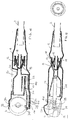
- the assembly shown in the Figures is mounted on the end of a support tube 2. At the opposite end of the support tube, there is a handset (not shown) to enable the equipment to be carried by a pedestrian operator. Equipment of this kind is shown, by way of example, in British Patent Application No. 8903243.7.
- the assembly comprises a housing 4 which is secured at one end to the support tube 2 and which carries, at the other end, a delivery head 6.
- the housing also accommodates a metering valve 8 and a calibration vessel 10.
- the metering valve 8 is adjustable manually by means of a knurled ring 12 which is accessible through openings 14 on opposite sides of the housing 4.
- a further opening 16 is provided in the housing, through which part of the wall of the calibration vessel 10 is visible, the calibration vessel 10 itself being made from transparent material.
- the metering valve 8 has an inlet spigot 18 on which is fitted a supply tube (not shown) which extends from the handset through the support tube 2.
- the outlet 20 of the metering valve 8 opens into the calibration vessel 10.
- the calibration vessel 10 itself has an outlet spigot 22 which is connected by a flexible tube 24 to an inlet spigot 26 of a connector element 28.
- the connector element 28 has an outlet spigot 30 which is received in an opening in the delivery head 6.
- the delivery head 6 has internal passageways which provide communication between the connector element 28 and an outlet (not shown) in a face 32 of the delivery head 6.
- the delivery head 6 accommodates an electric motor (not shown) which drives a spinning disc, situated adjacent the face 32, about an axis 34.
- a portion 36 of the wall of the housing 4 is provided with a boss (not shown) which engages a recess in the delivery head 6.
- the spigot 30 and the boss on the wall portion 36 thus support the delivery head 6 within the housing 4 for pivotal movement about an axis 38, which axis is perpendicular to the axis 34.
- the connector element 28 and the flexible tube 24 are accommodated within a projecting region 40 of the housing 4. This region 40 is disposed on the opposite side of the housing 4 from the window 16. Apertures 42 are provided in the projecting region 40, and these apertures receive projections 44 formed on the connector element 28.
- the connector element 28 is made from a transparent or translucent material.
- herbicide flows from the handset through the flexible tube provided in the support tube 2 to the spigot 18 of the metering valve 8.
- the flow rate through the metering valve 8 is regulated by appropriate adjustment of the ring 12, so that the herbicide flows, at a desired flow rate, through the calibration vessel 10 and the flexible tube 24 to the connector element 28.
- the herbicide flows into the delivery head 6 to be discharged over the plants to be treated by the spinning disc rotating about the axis 34. If it is desired to check the flow rate of herbicide to the delivery head 6, this can be done by operating the equipment for a predetermined time and establishing the volume of herbicide which enters the calibration vessel 10.
- the equipment would be held by an operator with the support tube 2 extending obliquely downwardly from the operator's hand so that the delivery head 6 is situated close to the plant to be treated. If the plant to be treated is at a relatively high level, the support tube 2 may be almost horizontal, in which case an orientation of the delivery head 6 as shown in Figure 5 would be appropriate. However, if the plant to be treated is nearer the ground, the support tube 2 would be more nearly vertical, and it would be appropriate for the delivery head to be pivoted relatively to the housing 4 in the clockwise direction from the position shown in Figure 5.
Landscapes
- Life Sciences & Earth Sciences (AREA)
- Engineering & Computer Science (AREA)
- Insects & Arthropods (AREA)
- Pest Control & Pesticides (AREA)
- Wood Science & Technology (AREA)
- Zoology (AREA)
- Environmental Sciences (AREA)
- Mechanical Engineering (AREA)
- Catching Or Destruction (AREA)
- Nozzles (AREA)
- Sampling And Sample Adjustment (AREA)
Priority Applications (4)
| Application Number | Priority Date | Filing Date | Title |
|---|---|---|---|
| EP90303899A EP0451387B1 (en) | 1990-04-11 | 1990-04-11 | Liquid delivery equipment |
| AT90303899T ATE107467T1 (de) | 1990-04-11 | 1990-04-11 | Gerät zum ausbringen von flüssigkeit. |
| ES90303899T ES2055323T3 (es) | 1990-04-11 | 1990-04-11 | Dispositivo para suministro de liquidos. |
| DE69010187T DE69010187D1 (de) | 1990-04-11 | 1990-04-11 | Gerät zum Ausbringen von Flüssigkeit. |
Applications Claiming Priority (1)
| Application Number | Priority Date | Filing Date | Title |
|---|---|---|---|
| EP90303899A EP0451387B1 (en) | 1990-04-11 | 1990-04-11 | Liquid delivery equipment |
Publications (2)
| Publication Number | Publication Date |
|---|---|
| EP0451387A1 EP0451387A1 (en) | 1991-10-16 |
| EP0451387B1 true EP0451387B1 (en) | 1994-06-22 |
Family
ID=8205370
Family Applications (1)
| Application Number | Title | Priority Date | Filing Date |
|---|---|---|---|
| EP90303899A Expired - Lifetime EP0451387B1 (en) | 1990-04-11 | 1990-04-11 | Liquid delivery equipment |
Country Status (4)
| Country | Link |
|---|---|
| EP (1) | EP0451387B1 (es) |
| AT (1) | ATE107467T1 (es) |
| DE (1) | DE69010187D1 (es) |
| ES (1) | ES2055323T3 (es) |
Citations (4)
| Publication number | Priority date | Publication date | Assignee | Title |
|---|---|---|---|---|
| DE1904374A1 (de) * | 1968-08-28 | 1970-04-09 | Sloan Valve Co | Brausekopf |
| EP0036287A1 (en) * | 1980-03-13 | 1981-09-23 | Chubb Fire Limited | Liquid-projecting monitor |
| US4394969A (en) * | 1977-12-20 | 1983-07-26 | Emile Jette | Showerhead control |
| DE3327786A1 (de) * | 1983-03-18 | 1985-02-21 | Hans Grohe Gmbh & Co Kg, 7622 Schiltach | Brausekopf mit einem brauseeinsatz |
Family Cites Families (5)
| Publication number | Priority date | Publication date | Assignee | Title |
|---|---|---|---|---|
| US2240392A (en) * | 1938-12-23 | 1941-04-29 | B S Allen | Nozzle |
| GB709151A (en) * | 1952-03-05 | 1954-05-19 | Shell Refining & Marketing Co | Improvements in or relating to spraying devices and processes |
| US3893630A (en) * | 1974-03-29 | 1975-07-08 | Hudson Mfg Co H D | Swivel outlet for sprayer or the like |
| FR2362673A1 (fr) * | 1976-03-08 | 1978-03-24 | Tecnoma | Pulverisateur portatif, notamment pour le traitement des cultures |
| IL87108A0 (en) * | 1987-07-20 | 1988-12-30 | Nomix Mfg Co Ltd | Equipment for delivering fluids |
-
1990
- 1990-04-11 AT AT90303899T patent/ATE107467T1/de not_active IP Right Cessation
- 1990-04-11 EP EP90303899A patent/EP0451387B1/en not_active Expired - Lifetime
- 1990-04-11 DE DE69010187T patent/DE69010187D1/de not_active Expired - Lifetime
- 1990-04-11 ES ES90303899T patent/ES2055323T3/es not_active Expired - Lifetime
Patent Citations (4)
| Publication number | Priority date | Publication date | Assignee | Title |
|---|---|---|---|---|
| DE1904374A1 (de) * | 1968-08-28 | 1970-04-09 | Sloan Valve Co | Brausekopf |
| US4394969A (en) * | 1977-12-20 | 1983-07-26 | Emile Jette | Showerhead control |
| EP0036287A1 (en) * | 1980-03-13 | 1981-09-23 | Chubb Fire Limited | Liquid-projecting monitor |
| DE3327786A1 (de) * | 1983-03-18 | 1985-02-21 | Hans Grohe Gmbh & Co Kg, 7622 Schiltach | Brausekopf mit einem brauseeinsatz |
Also Published As
| Publication number | Publication date |
|---|---|
| ATE107467T1 (de) | 1994-07-15 |
| DE69010187D1 (de) | 1994-07-28 |
| EP0451387A1 (en) | 1991-10-16 |
| ES2055323T3 (es) | 1994-08-16 |
Similar Documents
| Publication | Publication Date | Title |
|---|---|---|
| US4862876A (en) | Dental and throat cleaning system | |
| EP0723814B1 (en) | Oscillating shower apparatus | |
| EP0168823B1 (en) | Hydromassage nozzle | |
| CA2071844C (en) | Pellet dispensing unit | |
| EP0451387B1 (en) | Liquid delivery equipment | |
| US4490311A (en) | Drum humidifier | |
| KR200493630Y1 (ko) | 극저온 치료장치 | |
| EP0169806B1 (de) | Sprayvorrichtung für Pflanzenschutzmittel | |
| US2622928A (en) | Sprinkler | |
| KR930002496B1 (ko) | 유체송출장치의 유량교정방법 및 기구 | |
| US6045010A (en) | Hand powered liquid chemical measuring and dispensing system | |
| EP0160477B1 (en) | Liquid spraying device | |
| EP1003611B1 (en) | An improved irrigation sprinkler | |
| JPH0372974A (ja) | 液体散布装置 | |
| CA1195962A (en) | Demountable wheeled liquid sprayer | |
| US11913815B2 (en) | Metering console | |
| CA2046481C (en) | Modular counter mounted fluid dispensing apparatus | |
| EP0685218B1 (fr) | Appareil portatif de premier secours pour le lavage d'un oeil et/ou de la peau | |
| CA1041061A (en) | Plastic trigger nozzle | |
| EP0294058A2 (en) | Cleaning brushes | |
| EP0657180B1 (en) | Metering device | |
| KR200163253Y1 (ko) | 트랙터용비료살포기 | |
| US4789003A (en) | Water treatment apparatus | |
| JP3949430B2 (ja) | 散布装置及び散布装置のアタッチメント | |
| JP2002112649A (ja) | 揺動散水防除機 |
Legal Events
| Date | Code | Title | Description |
|---|---|---|---|
| PUAI | Public reference made under article 153(3) epc to a published international application that has entered the european phase |
Free format text: ORIGINAL CODE: 0009012 |
|
| AK | Designated contracting states |
Kind code of ref document: A1 Designated state(s): AT BE CH DE DK ES FR GB GR IT LI LU NL SE |
|
| 17P | Request for examination filed |
Effective date: 19920408 |
|
| 17Q | First examination report despatched |
Effective date: 19920525 |
|
| GRAA | (expected) grant |
Free format text: ORIGINAL CODE: 0009210 |
|
| AK | Designated contracting states |
Kind code of ref document: B1 Designated state(s): AT BE CH DE DK ES FR GB GR IT LI LU NL SE |
|
| PG25 | Lapsed in a contracting state [announced via postgrant information from national office to epo] |
Ref country code: IT Free format text: LAPSE BECAUSE OF FAILURE TO SUBMIT A TRANSLATION OF THE DESCRIPTION OR TO PAY THE FEE WITHIN THE PRESCRIBED TIME-LIMIT;WARNING: LAPSES OF ITALIAN PATENTS WITH EFFECTIVE DATE BEFORE 2007 MAY HAVE OCCURRED AT ANY TIME BEFORE 2007. THE CORRECT EFFECTIVE DATE MAY BE DIFFERENT FROM THE ONE RECORDED. Effective date: 19940622 Ref country code: GR Free format text: LAPSE BECAUSE OF FAILURE TO SUBMIT A TRANSLATION OF THE DESCRIPTION OR TO PAY THE FEE WITHIN THE PRESCRIBED TIME-LIMIT Effective date: 19940622 Ref country code: BE Effective date: 19940622 Ref country code: NL Effective date: 19940622 Ref country code: AT Effective date: 19940622 Ref country code: CH Effective date: 19940622 Ref country code: LI Effective date: 19940622 Ref country code: DK Effective date: 19940622 |
|
| REF | Corresponds to: |
Ref document number: 107467 Country of ref document: AT Date of ref document: 19940715 Kind code of ref document: T |
|
| REF | Corresponds to: |
Ref document number: 69010187 Country of ref document: DE Date of ref document: 19940728 |
|
| REG | Reference to a national code |
Ref country code: ES Ref legal event code: FG2A Ref document number: 2055323 Country of ref document: ES Kind code of ref document: T3 |
|
| ET | Fr: translation filed | ||
| PG25 | Lapsed in a contracting state [announced via postgrant information from national office to epo] |
Ref country code: SE Effective date: 19940922 |
|
| PG25 | Lapsed in a contracting state [announced via postgrant information from national office to epo] |
Ref country code: DE Effective date: 19940923 |
|
| REG | Reference to a national code |
Ref country code: CH Ref legal event code: PL |
|
| NLV1 | Nl: lapsed or annulled due to failure to fulfill the requirements of art. 29p and 29m of the patents act | ||
| PLBE | No opposition filed within time limit |
Free format text: ORIGINAL CODE: 0009261 |
|
| STAA | Information on the status of an ep patent application or granted ep patent |
Free format text: STATUS: NO OPPOSITION FILED WITHIN TIME LIMIT |
|
| PG25 | Lapsed in a contracting state [announced via postgrant information from national office to epo] |
Ref country code: LU Free format text: LAPSE BECAUSE OF NON-PAYMENT OF DUE FEES Effective date: 19950430 |
|
| 26N | No opposition filed | ||
| PGFP | Annual fee paid to national office [announced via postgrant information from national office to epo] |
Ref country code: ES Payment date: 19980406 Year of fee payment: 9 |
|
| PG25 | Lapsed in a contracting state [announced via postgrant information from national office to epo] |
Ref country code: ES Free format text: LAPSE BECAUSE OF NON-PAYMENT OF DUE FEES Effective date: 19990412 |
|
| PGFP | Annual fee paid to national office [announced via postgrant information from national office to epo] |
Ref country code: FR Payment date: 20000417 Year of fee payment: 11 |
|
| PG25 | Lapsed in a contracting state [announced via postgrant information from national office to epo] |
Ref country code: FR Free format text: THE PATENT HAS BEEN ANNULLED BY A DECISION OF A NATIONAL AUTHORITY Effective date: 20010430 |
|
| REG | Reference to a national code |
Ref country code: ES Ref legal event code: FD2A Effective date: 20010503 |
|
| REG | Reference to a national code |
Ref country code: GB Ref legal event code: IF02 |
|
| REG | Reference to a national code |
Ref country code: FR Ref legal event code: ST |
|
| PGFP | Annual fee paid to national office [announced via postgrant information from national office to epo] |
Ref country code: GB Payment date: 20030401 Year of fee payment: 14 |
|
| PG25 | Lapsed in a contracting state [announced via postgrant information from national office to epo] |
Ref country code: GB Free format text: LAPSE BECAUSE OF NON-PAYMENT OF DUE FEES Effective date: 20040411 |
|
| GBPC | Gb: european patent ceased through non-payment of renewal fee |
Effective date: 20040411 |