EP0451387A1 - Liquid delivery equipment - Google Patents
Liquid delivery equipment Download PDFInfo
- Publication number
- EP0451387A1 EP0451387A1 EP90303899A EP90303899A EP0451387A1 EP 0451387 A1 EP0451387 A1 EP 0451387A1 EP 90303899 A EP90303899 A EP 90303899A EP 90303899 A EP90303899 A EP 90303899A EP 0451387 A1 EP0451387 A1 EP 0451387A1
- Authority
- EP
- European Patent Office
- Prior art keywords
- delivery head
- equipment
- connector element
- delivery
- support member
- Prior art date
- Legal status (The legal status is an assumption and is not a legal conclusion. Google has not performed a legal analysis and makes no representation as to the accuracy of the status listed.)
- Granted
Links
Images

Classifications
-
- A—HUMAN NECESSITIES
- A01—AGRICULTURE; FORESTRY; ANIMAL HUSBANDRY; HUNTING; TRAPPING; FISHING
- A01M—CATCHING, TRAPPING OR SCARING OF ANIMALS; APPARATUS FOR THE DESTRUCTION OF NOXIOUS ANIMALS OR NOXIOUS PLANTS
- A01M7/00—Special adaptations or arrangements of liquid-spraying apparatus for purposes covered by this subclass
- A01M7/0025—Mechanical sprayers
- A01M7/0028—Centrifugal sprayers
-
- A—HUMAN NECESSITIES
- A01—AGRICULTURE; FORESTRY; ANIMAL HUSBANDRY; HUNTING; TRAPPING; FISHING
- A01M—CATCHING, TRAPPING OR SCARING OF ANIMALS; APPARATUS FOR THE DESTRUCTION OF NOXIOUS ANIMALS OR NOXIOUS PLANTS
- A01M7/00—Special adaptations or arrangements of liquid-spraying apparatus for purposes covered by this subclass
- A01M7/005—Special arrangements or adaptations of the spraying or distributing parts, e.g. adaptations or mounting of the spray booms, mounting of the nozzles, protection shields
- A01M7/006—Mounting of the nozzles
-
- B—PERFORMING OPERATIONS; TRANSPORTING
- B05—SPRAYING OR ATOMISING IN GENERAL; APPLYING FLUENT MATERIALS TO SURFACES, IN GENERAL
- B05B—SPRAYING APPARATUS; ATOMISING APPARATUS; NOZZLES
- B05B15/00—Details of spraying plant or spraying apparatus not otherwise provided for; Accessories
- B05B15/60—Arrangements for mounting, supporting or holding spraying apparatus
- B05B15/68—Arrangements for adjusting the position of spray heads
Definitions
- This invention relates to liquid delivery equipment and is particularly, although not exclusively, concerned with applicators for distributing agrochemicals such as herbicide.
- Herbicide applicators comprise a handset from which extends a support tube carrying a delivery head at the end away from the handset.
- the delivery head has means, such as a spinning disc, for distributing the herbicide.
- the spinning disc it is desirable for the spinning disc to rotate about a generally vertical axis.
- the distribution head is mounted rigidly on the support tube, it is not possible to maintain this vertical orientation of the spinning disc axis as the delivery head is raised and lowered to dispense herbicide at different heights.
- the orientation of the delivery head is set so as to be appropriate for distributing herbicide over weeds at ground level, the orientation of the axis of the spinning disc will be incorrect when distributing herbicide over plants at, for example, waist level.
- liquid delivery equipment comprising a support member carrying a delivery head, the delivery head being mounted pivotably on the support member for adjustment of the direction of discharge of liquid from the delivery head relatively to the support member, pivotal support of the delivery head on the support member being accomplished at least partly by a connector element through which liquid is conveyed from the support member to the delivery head.
- the delivery head is supported on one side by the connector element and on the opposite side by a further support element.
- the connector element preferably has a first part which engages the delivery head and extends parallel to the pivotal axis, and a second part which extends perpendicular to the pivotal axis. To support the delivery head, the connector element may be received in an opening in the delivery head.
- the connector element may be made from transparent material, or include a transparent portion, which is exposed to the outside of the equipment, so that an operator can determine whether or not liquid is flowing through the connector element.
- the delivery head is pivotably mounted within a housing which is carried rigidly on a support member.
- the support member may, for example, be a tubular support having a handset at the end away from the delivery head so that the equipment may be carried by a pedestrian operator.
- the housing preferably accommodates the connector element, and an appropriately positioned aperture may be provided in the housing to expose the connector element if it is transparent, or has a transparent portion.
- the housing may also accommodate a metering valve for controlling the flow of liquid to the delivery head, and a calibration vessel for use in checking the output from the metering valve.
- the delivery head may be provided with a spinning disc for distributing the liquid, and may accommodate and electric motor for driving the spinning disc.
- the assembly shown in the Figures is mounted on the end of a support tube 2. At the opposite end of the support tube, there is a handset (not shown) to enable the equipment to be carried by a pedestrian operator. Equipment of this kind is shown, by way of example, in British Patent Application No. 8903243.7.
- the assembly comprises a housing 4 which is secured at one end to the support tube 2 and which carries, at the other end, a delivery head 6.
- the housing also accommodates a metering valve 8 and a calibration vessel 10.
- the metering valve 8 is adjustable manually by means of a knurled ring 12 which is accessible through openings 14 on opposite sides of the housing 4.
- a further opening 16 is provided in the housing, through which part of the wall of the calibration vessel 10 is visible, the calibration vessel 10 itself being made from transparent material.
- the metering valve 8 has an inlet spigot 18 on which is fitted a supply tube (not shown) which extends from the handset through the support tube 2.
- the outlet 20 of the metering valve 8 opens into the calibration vessel 10.
- the calibration vessel 10 itself has an outlet spigot 22 which is connected by a flexible tube 24 to an inlet spigot 26 of a connector element 28.
- the connector element 28 has an outlet spigot 30 which is received in an opening in the delivery head 6.
- the delivery head 6 has internal passageways which provide communication between the connector element 28 and an outlet (not shown) in a face 32 of the delivery head 6.
- the delivery head 6 accommodates an electric motor (not shown) which drives a spinning disc, situated adjacent the face 32, about an axis 34.
- a portion 36 of the wall of the housing 4 is provided with a boss (not shown) which engages a recess in the delivery head 6.
- the spigot 30 and the boss on the wall portion 36 thus support the delivery head 6 within the housing 4 for pivotal movement about an axis 38, which axis is perpendicular to the axis 34.
- the connector element 28 and the flexible tube 24 are accommodated within a projecting region 40 of the housing 4. This region 40 is disposed on the opposite side of the housing 4 from the window 16. Apertures 42 are provided in the projecting region 40, and these apertures receive projections 44 formed on the connector element 28.
- the connector element 28 is made from a transparent or translucent material.
- herbicide flows from the handset through the flexible tube provided in the support tube 2 to the spigot 18 of the metering valve 8.
- the flow rate through the metering valve 8 is regulated by appropriate adjustment of the ring 12, so that the herbicide flows, at a desired flow rate, through the calibration vessel 10 and the flexible tube 24 to the connector element 28.
- the herbicide flows into the delivery head 6 to be discharged over the plants to be treated by the spinning disc rotating about the axis 34. If it is desired to check the flow rate of herbicide to the delivery head 6, this can be done by operating the equipment for a predetermined time and establishing the volume of herbicide which enters the calibration vessel 10.
- the equipment would be held by an operator with the support tube 2 extending obliquely downwardly from the operator's hand so that the delivery head 6 is situated close to the plant to be treated. If the plant to be treated is at a relatively high level, the support tube 2 may be almost horizontal, in which case an orientation of the delivery head 6 as shown in Figure 5 would be appropriate. However, if the plant to be treated is nearer the ground, the support tube 2 would be more nearly vertical, and it would be appropriate for the delivery head to be pivoted relatively to the housing 4 in the clockwise direction from the position shown in Figure 5.
Abstract
Description
- This invention relates to liquid delivery equipment and is particularly, although not exclusively, concerned with applicators for distributing agrochemicals such as herbicide.
- Herbicide applicators are known which comprise a handset from which extends a support tube carrying a delivery head at the end away from the handset. The delivery head has means, such as a spinning disc, for distributing the herbicide.
- It is desirable for the spinning disc to rotate about a generally vertical axis. However, if the distribution head is mounted rigidly on the support tube, it is not possible to maintain this vertical orientation of the spinning disc axis as the delivery head is raised and lowered to dispense herbicide at different heights. Thus, for example, if the orientation of the delivery head is set so as to be appropriate for distributing herbicide over weeds at ground level, the orientation of the axis of the spinning disc will be incorrect when distributing herbicide over plants at, for example, waist level.
- It is known to mount the delivery head pivotably on a support tube by means of a crude pivot and butterfly nut connection. Herbicide is then supplied from the handset through the support tube to the delivery head through a flexible tube which extends from the support tube to the delivery head on the outside of the equipment, the flexibility of the tube permitting pivotal adjustment of the distribution head. However, the unprotected flexible tube is exposed to damage, and also makes it difficult to achieve a clean, integrated design of the distribution head.
- According to the present invention there is provided liquid delivery equipment comprising a support member carrying a delivery head, the delivery head being mounted pivotably on the support member for adjustment of the direction of discharge of liquid from the delivery head relatively to the support member, pivotal support of the delivery head on the support member being accomplished at least partly by a connector element through which liquid is conveyed from the support member to the delivery head.
- In a preferred embodiment, the delivery head is supported on one side by the connector element and on the opposite side by a further support element. The connector element preferably has a first part which engages the delivery head and extends parallel to the pivotal axis, and a second part which extends perpendicular to the pivotal axis. To support the delivery head, the connector element may be received in an opening in the delivery head.
- It is desirable for an operator to be able to determine visually whether or not liquid is flowing to the delivery head. For this purpose, the connector element may be made from transparent material, or include a transparent portion, which is exposed to the outside of the equipment, so that an operator can determine whether or not liquid is flowing through the connector element.
- In a preferred embodiment, the delivery head is pivotably mounted within a housing which is carried rigidly on a support member. The support member may, for example, be a tubular support having a handset at the end away from the delivery head so that the equipment may be carried by a pedestrian operator. The housing preferably accommodates the connector element, and an appropriately positioned aperture may be provided in the housing to expose the connector element if it is transparent, or has a transparent portion. The housing may also accommodate a metering valve for controlling the flow of liquid to the delivery head, and a calibration vessel for use in checking the output from the metering valve.
- The delivery head may be provided with a spinning disc for distributing the liquid, and may accommodate and electric motor for driving the spinning disc.
- For a better understanding of the present invention, and to show how it may be carried into effect, reference will now be made, by way of example, to the accompanying drawings, in which:
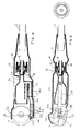
- Figure 1 is a side view of a delivery assembly of a herbicide applicator;
- Figure 2 is a top view of the delivery assembly shown in Figure 1;
- Figure 3 shows the other side of the delivery assembly of Figure 1;
- Figure 4 is a sectional view taken on the line IV-IV in Figure 3; and
- Figure 5 is a sectional view taken on the line V-V in Figure 2.
- The assembly shown in the Figures is mounted on the end of a
support tube 2. At the opposite end of the support tube, there is a handset (not shown) to enable the equipment to be carried by a pedestrian operator. Equipment of this kind is shown, by way of example, in British Patent Application No. 8903243.7. The assembly comprises ahousing 4 which is secured at one end to thesupport tube 2 and which carries, at the other end, adelivery head 6. The housing also accommodates a metering valve 8 and acalibration vessel 10. The metering valve 8 is adjustable manually by means of a knurledring 12 which is accessible throughopenings 14 on opposite sides of thehousing 4. Afurther opening 16 is provided in the housing, through which part of the wall of thecalibration vessel 10 is visible, thecalibration vessel 10 itself being made from transparent material. - The metering valve 8 has an
inlet spigot 18 on which is fitted a supply tube (not shown) which extends from the handset through thesupport tube 2. Theoutlet 20 of the metering valve 8 opens into thecalibration vessel 10. Thecalibration vessel 10 itself has anoutlet spigot 22 which is connected by aflexible tube 24 to aninlet spigot 26 of aconnector element 28. Theconnector element 28 has an outlet spigot 30 which is received in an opening in thedelivery head 6. Thedelivery head 6 has internal passageways which provide communication between theconnector element 28 and an outlet (not shown) in aface 32 of thedelivery head 6. - The
delivery head 6 accommodates an electric motor (not shown) which drives a spinning disc, situated adjacent theface 32, about anaxis 34. - On the side of the
delivery head 6 away from theconnector element 28, aportion 36 of the wall of thehousing 4 is provided with a boss (not shown) which engages a recess in thedelivery head 6. The spigot 30 and the boss on thewall portion 36 thus support thedelivery head 6 within thehousing 4 for pivotal movement about anaxis 38, which axis is perpendicular to theaxis 34. - The
connector element 28 and theflexible tube 24 are accommodated within a projectingregion 40 of thehousing 4. Thisregion 40 is disposed on the opposite side of thehousing 4 from thewindow 16.Apertures 42 are provided in the projectingregion 40, and these apertures receiveprojections 44 formed on theconnector element 28. Theconnector element 28 is made from a transparent or translucent material. - In use, herbicide flows from the handset through the flexible tube provided in the
support tube 2 to thespigot 18 of the metering valve 8. The flow rate through the metering valve 8 is regulated by appropriate adjustment of thering 12, so that the herbicide flows, at a desired flow rate, through thecalibration vessel 10 and theflexible tube 24 to theconnector element 28. From theconnector element 28, the herbicide flows into thedelivery head 6 to be discharged over the plants to be treated by the spinning disc rotating about theaxis 34. If it is desired to check the flow rate of herbicide to thedelivery head 6, this can be done by operating the equipment for a predetermined time and establishing the volume of herbicide which enters thecalibration vessel 10. - It will be appreciated that the equipment would be held by an operator with the
support tube 2 extending obliquely downwardly from the operator's hand so that thedelivery head 6 is situated close to the plant to be treated. If the plant to be treated is at a relatively high level, thesupport tube 2 may be almost horizontal, in which case an orientation of thedelivery head 6 as shown in Figure 5 would be appropriate. However, if the plant to be treated is nearer the ground, thesupport tube 2 would be more nearly vertical, and it would be appropriate for the delivery head to be pivoted relatively to thehousing 4 in the clockwise direction from the position shown in Figure 5. This can be achieved simply by pivoting thedelivery head 6 manually about theaxis 38, this movement being permitted by the pivotal support provided by the outlet spigot 30 of theconnector 28 and the boss on thewall portion 36. Adequate sealing is provided between the outlet spigot 30 and the recess in the delivery head, to prevent leakage of herbicide at this point. Also, some frictional resistance to pivoting is provided, to ensure that thedelivery head 6 remains in the position in which it is set.
Claims (11)
- Liquid delivery equipment comprising a support member carrying a delivery head, the delivery head being mounted pivotably on the support member for adjustment of the direction of discharge of liquid from the delivery head relatively to the support member, pivotal support of the delivery head on the support member being accomplished at least partly by a connector element through which liquid is conveyed from the support member to the delivery head.
- Equipment as claimed in claim 1, in which the delivery head is supported by the connector element on one side and by a further support element on the opposite side.
- Equipment as claimed in claim 1 or 2, in which the connector element has a first part extending parallel to the pivot axis and a second part extending perpendicular to the pivot axis.
- Equipment as claimed in any one of the preceding claims, in which the connector element engages an opening in the delivery head to provide pivotal support for the delivery head.
- Equipment as claimed in any one of the preceding claims, in which the connector element has an exposed transparent region for providing a visual indication of flow of liquid through the connector element.
- Equipment as claimed in any one of the preceding claims, in which the delivery head is pivotally mounted in a housing carried by the support member.
- Equipment as claimed in claim 6, in which the housing accommodates the connector element.
- Equipment as claimed in claim 6 to 7, in which the housing accommodates a metering valve and a calibration vessel.
- Equipment as claimed in any one of the preceding claims, in which the delivery head accommodates an electric motor for driving a distribution element fitted to the delivery head.
- Equipment as claimed in any one of the preceding claims, which is an applicator for agrochemicals.
- Liquid delivery equipment substantially as described herein with reference to, and as shown in, the accompanying drawings.
Priority Applications (4)
| Application Number | Priority Date | Filing Date | Title |
|---|---|---|---|
| EP90303899A EP0451387B1 (en) | 1990-04-11 | 1990-04-11 | Liquid delivery equipment |
| ES90303899T ES2055323T3 (en) | 1990-04-11 | 1990-04-11 | DEVICE FOR SUPPLY OF LIQUIDS. |
| DE69010187T DE69010187D1 (en) | 1990-04-11 | 1990-04-11 | Device for dispensing liquid. |
| AT90303899T ATE107467T1 (en) | 1990-04-11 | 1990-04-11 | DEVICE FOR SPREADING LIQUID. |
Applications Claiming Priority (1)
| Application Number | Priority Date | Filing Date | Title |
|---|---|---|---|
| EP90303899A EP0451387B1 (en) | 1990-04-11 | 1990-04-11 | Liquid delivery equipment |
Publications (2)
| Publication Number | Publication Date |
|---|---|
| EP0451387A1 true EP0451387A1 (en) | 1991-10-16 |
| EP0451387B1 EP0451387B1 (en) | 1994-06-22 |
Family
ID=8205370
Family Applications (1)
| Application Number | Title | Priority Date | Filing Date |
|---|---|---|---|
| EP90303899A Expired - Lifetime EP0451387B1 (en) | 1990-04-11 | 1990-04-11 | Liquid delivery equipment |
Country Status (4)
| Country | Link |
|---|---|
| EP (1) | EP0451387B1 (en) |
| AT (1) | ATE107467T1 (en) |
| DE (1) | DE69010187D1 (en) |
| ES (1) | ES2055323T3 (en) |
Citations (5)
| Publication number | Priority date | Publication date | Assignee | Title |
|---|---|---|---|---|
| US2240392A (en) * | 1938-12-23 | 1941-04-29 | B S Allen | Nozzle |
| GB709151A (en) * | 1952-03-05 | 1954-05-19 | Shell Refining & Marketing Co | Improvements in or relating to spraying devices and processes |
| US3893630A (en) * | 1974-03-29 | 1975-07-08 | Hudson Mfg Co H D | Swivel outlet for sprayer or the like |
| FR2362673A1 (en) * | 1976-03-08 | 1978-03-24 | Tecnoma | Electric motor driven portable plant spray - has folding handle housing electric batteries and carrying rotary head with applicator liquid bottle |
| EP0300762A1 (en) * | 1987-07-20 | 1989-01-25 | Nomix-Chipman Limited | Equipment for delivering fluid |
Family Cites Families (3)
| Publication number | Priority date | Publication date | Assignee | Title |
|---|---|---|---|---|
| US4394969A (en) * | 1977-12-20 | 1983-07-26 | Emile Jette | Showerhead control |
| AU536147B2 (en) * | 1980-03-13 | 1984-04-19 | Chubb Fire Security Ltd. | Liquid-projecting monitor |
| DE3327786A1 (en) * | 1983-03-18 | 1985-02-21 | Hans Grohe Gmbh & Co Kg, 7622 Schiltach | Shower head with a shower insert |
-
1990
- 1990-04-11 DE DE69010187T patent/DE69010187D1/en not_active Expired - Lifetime
- 1990-04-11 AT AT90303899T patent/ATE107467T1/en not_active IP Right Cessation
- 1990-04-11 ES ES90303899T patent/ES2055323T3/en not_active Expired - Lifetime
- 1990-04-11 EP EP90303899A patent/EP0451387B1/en not_active Expired - Lifetime
Patent Citations (5)
| Publication number | Priority date | Publication date | Assignee | Title |
|---|---|---|---|---|
| US2240392A (en) * | 1938-12-23 | 1941-04-29 | B S Allen | Nozzle |
| GB709151A (en) * | 1952-03-05 | 1954-05-19 | Shell Refining & Marketing Co | Improvements in or relating to spraying devices and processes |
| US3893630A (en) * | 1974-03-29 | 1975-07-08 | Hudson Mfg Co H D | Swivel outlet for sprayer or the like |
| FR2362673A1 (en) * | 1976-03-08 | 1978-03-24 | Tecnoma | Electric motor driven portable plant spray - has folding handle housing electric batteries and carrying rotary head with applicator liquid bottle |
| EP0300762A1 (en) * | 1987-07-20 | 1989-01-25 | Nomix-Chipman Limited | Equipment for delivering fluid |
Also Published As
| Publication number | Publication date |
|---|---|
| EP0451387B1 (en) | 1994-06-22 |
| DE69010187D1 (en) | 1994-07-28 |
| ATE107467T1 (en) | 1994-07-15 |
| ES2055323T3 (en) | 1994-08-16 |
Similar Documents
| Publication | Publication Date | Title |
|---|---|---|
| KR910001898B1 (en) | Variable dilution ratio hose-end sprayer | |
| US4862876A (en) | Dental and throat cleaning system | |
| CA2056705A1 (en) | Restrictor valve for a metered liquid dispensing system | |
| CA2071844C (en) | Pellet dispensing unit | |
| EP0168823A2 (en) | Hydromassage nozzle | |
| US20050081319A1 (en) | Floor-cleaning machine with manual adjustment for two distinct and repeatable fluid flow rates | |
| US6974245B2 (en) | Device for mixing a liquid fertilizer with a flow of water, for use by individuals | |
| CA2333834A1 (en) | Seed inoculation system | |
| EP0451387A1 (en) | Liquid delivery equipment | |
| US4490311A (en) | Drum humidifier | |
| EP0169806B1 (en) | Spray device for plant protection solutions | |
| US4628960A (en) | Sprayer sight gauge | |
| EP0363717A2 (en) | Improvement in oscillating lawn sprinklers | |
| US5328283A (en) | Multi-function glass cleaning apparatus | |
| US4889001A (en) | Calibration of fluid delivery equipment | |
| JPH02136716A (en) | Flow rate measuring apparatus | |
| US6045010A (en) | Hand powered liquid chemical measuring and dispensing system | |
| US6299443B1 (en) | Device and method for cleaning teeth and gums | |
| EP0160477B1 (en) | Liquid spraying device | |
| CA2046481C (en) | Modular counter mounted fluid dispensing apparatus | |
| US11913815B2 (en) | Metering console | |
| GB2091134A (en) | Portable liquid sprayers | |
| CN220506920U (en) | Indoor unit of air conditioner and air conditioner | |
| US4844345A (en) | Aspirator tray | |
| EP0657180B1 (en) | Metering device |
Legal Events
| Date | Code | Title | Description |
|---|---|---|---|
| PUAI | Public reference made under article 153(3) epc to a published international application that has entered the european phase |
Free format text: ORIGINAL CODE: 0009012 |
|
| AK | Designated contracting states |
Kind code of ref document: A1 Designated state(s): AT BE CH DE DK ES FR GB GR IT LI LU NL SE |
|
| 17P | Request for examination filed |
Effective date: 19920408 |
|
| 17Q | First examination report despatched |
Effective date: 19920525 |
|
| GRAA | (expected) grant |
Free format text: ORIGINAL CODE: 0009210 |
|
| AK | Designated contracting states |
Kind code of ref document: B1 Designated state(s): AT BE CH DE DK ES FR GB GR IT LI LU NL SE |
|
| PG25 | Lapsed in a contracting state [announced via postgrant information from national office to epo] |
Ref country code: IT Free format text: LAPSE BECAUSE OF FAILURE TO SUBMIT A TRANSLATION OF THE DESCRIPTION OR TO PAY THE FEE WITHIN THE PRESCRIBED TIME-LIMIT;WARNING: LAPSES OF ITALIAN PATENTS WITH EFFECTIVE DATE BEFORE 2007 MAY HAVE OCCURRED AT ANY TIME BEFORE 2007. THE CORRECT EFFECTIVE DATE MAY BE DIFFERENT FROM THE ONE RECORDED. Effective date: 19940622 Ref country code: GR Free format text: LAPSE BECAUSE OF FAILURE TO SUBMIT A TRANSLATION OF THE DESCRIPTION OR TO PAY THE FEE WITHIN THE PRESCRIBED TIME-LIMIT Effective date: 19940622 Ref country code: BE Effective date: 19940622 Ref country code: NL Effective date: 19940622 Ref country code: AT Effective date: 19940622 Ref country code: CH Effective date: 19940622 Ref country code: LI Effective date: 19940622 Ref country code: DK Effective date: 19940622 |
|
| REF | Corresponds to: |
Ref document number: 107467 Country of ref document: AT Date of ref document: 19940715 Kind code of ref document: T |
|
| REF | Corresponds to: |
Ref document number: 69010187 Country of ref document: DE Date of ref document: 19940728 |
|
| REG | Reference to a national code |
Ref country code: ES Ref legal event code: FG2A Ref document number: 2055323 Country of ref document: ES Kind code of ref document: T3 |
|
| ET | Fr: translation filed | ||
| PG25 | Lapsed in a contracting state [announced via postgrant information from national office to epo] |
Ref country code: SE Effective date: 19940922 |
|
| PG25 | Lapsed in a contracting state [announced via postgrant information from national office to epo] |
Ref country code: DE Effective date: 19940923 |
|
| REG | Reference to a national code |
Ref country code: CH Ref legal event code: PL |
|
| NLV1 | Nl: lapsed or annulled due to failure to fulfill the requirements of art. 29p and 29m of the patents act | ||
| PLBE | No opposition filed within time limit |
Free format text: ORIGINAL CODE: 0009261 |
|
| STAA | Information on the status of an ep patent application or granted ep patent |
Free format text: STATUS: NO OPPOSITION FILED WITHIN TIME LIMIT |
|
| PG25 | Lapsed in a contracting state [announced via postgrant information from national office to epo] |
Ref country code: LU Free format text: LAPSE BECAUSE OF NON-PAYMENT OF DUE FEES Effective date: 19950430 |
|
| 26N | No opposition filed | ||
| PGFP | Annual fee paid to national office [announced via postgrant information from national office to epo] |
Ref country code: ES Payment date: 19980406 Year of fee payment: 9 |
|
| PG25 | Lapsed in a contracting state [announced via postgrant information from national office to epo] |
Ref country code: ES Free format text: LAPSE BECAUSE OF NON-PAYMENT OF DUE FEES Effective date: 19990412 |
|
| PGFP | Annual fee paid to national office [announced via postgrant information from national office to epo] |
Ref country code: FR Payment date: 20000417 Year of fee payment: 11 |
|
| PG25 | Lapsed in a contracting state [announced via postgrant information from national office to epo] |
Ref country code: FR Free format text: THE PATENT HAS BEEN ANNULLED BY A DECISION OF A NATIONAL AUTHORITY Effective date: 20010430 |
|
| REG | Reference to a national code |
Ref country code: ES Ref legal event code: FD2A Effective date: 20010503 |
|
| REG | Reference to a national code |
Ref country code: GB Ref legal event code: IF02 |
|
| REG | Reference to a national code |
Ref country code: FR Ref legal event code: ST |
|
| PGFP | Annual fee paid to national office [announced via postgrant information from national office to epo] |
Ref country code: GB Payment date: 20030401 Year of fee payment: 14 |
|
| PG25 | Lapsed in a contracting state [announced via postgrant information from national office to epo] |
Ref country code: GB Free format text: LAPSE BECAUSE OF NON-PAYMENT OF DUE FEES Effective date: 20040411 |
|
| GBPC | Gb: european patent ceased through non-payment of renewal fee |
Effective date: 20040411 |