EP0451058B1 - Method and apparatus for discarding a tubing in an access well to a salt cavity for gas storage - Google Patents
Method and apparatus for discarding a tubing in an access well to a salt cavity for gas storage Download PDFInfo
- Publication number
- EP0451058B1 EP0451058B1 EP19910400921 EP91400921A EP0451058B1 EP 0451058 B1 EP0451058 B1 EP 0451058B1 EP 19910400921 EP19910400921 EP 19910400921 EP 91400921 A EP91400921 A EP 91400921A EP 0451058 B1 EP0451058 B1 EP 0451058B1
- Authority
- EP
- European Patent Office
- Prior art keywords
- cutting
- tool
- tubing
- tubular body
- piston
- Prior art date
- Legal status (The legal status is an assumption and is not a legal conclusion. Google has not performed a legal analysis and makes no representation as to the accuracy of the status listed.)
- Expired - Lifetime
Links
- 238000000034 method Methods 0.000 title claims description 11
- 150000003839 salts Chemical class 0.000 title claims description 11
- 238000003860 storage Methods 0.000 title description 9
- 238000005520 cutting process Methods 0.000 claims description 86
- 238000004873 anchoring Methods 0.000 claims description 52
- 238000004891 communication Methods 0.000 claims description 3
- 230000000295 complement effect Effects 0.000 claims description 3
- 238000006073 displacement reaction Methods 0.000 claims description 2
- 238000007373 indentation Methods 0.000 claims 6
- 239000007789 gas Substances 0.000 description 23
- FAPWRFPIFSIZLT-UHFFFAOYSA-M Sodium chloride Chemical compound [Na+].[Cl-] FAPWRFPIFSIZLT-UHFFFAOYSA-M 0.000 description 16
- 230000000694 effects Effects 0.000 description 16
- 239000011780 sodium chloride Substances 0.000 description 16
- XLYOFNOQVPJJNP-UHFFFAOYSA-N water Substances O XLYOFNOQVPJJNP-UHFFFAOYSA-N 0.000 description 14
- VNWKTOKETHGBQD-UHFFFAOYSA-N methane Chemical compound C VNWKTOKETHGBQD-UHFFFAOYSA-N 0.000 description 10
- 238000009434 installation Methods 0.000 description 8
- IJGRMHOSHXDMSA-UHFFFAOYSA-N Atomic nitrogen Chemical compound N#N IJGRMHOSHXDMSA-UHFFFAOYSA-N 0.000 description 6
- 239000012267 brine Substances 0.000 description 5
- 239000003345 natural gas Substances 0.000 description 5
- HPALAKNZSZLMCH-UHFFFAOYSA-M sodium;chloride;hydrate Chemical compound O.[Na+].[Cl-] HPALAKNZSZLMCH-UHFFFAOYSA-M 0.000 description 5
- 238000002347 injection Methods 0.000 description 4
- 239000007924 injection Substances 0.000 description 4
- 229910052757 nitrogen Inorganic materials 0.000 description 3
- 238000007789 sealing Methods 0.000 description 3
- 238000003892 spreading Methods 0.000 description 3
- 230000006835 compression Effects 0.000 description 2
- 238000007906 compression Methods 0.000 description 2
- 239000013505 freshwater Substances 0.000 description 2
- 230000002706 hydrostatic effect Effects 0.000 description 2
- 230000036316 preload Effects 0.000 description 2
- 239000011435 rock Substances 0.000 description 2
- 238000000926 separation method Methods 0.000 description 2
- 241000920340 Pion Species 0.000 description 1
- 238000010009 beating Methods 0.000 description 1
- 230000000903 blocking effect Effects 0.000 description 1
- 238000004090 dissolution Methods 0.000 description 1
- 230000008030 elimination Effects 0.000 description 1
- 238000003379 elimination reaction Methods 0.000 description 1
- 239000002360 explosive Substances 0.000 description 1
- 230000001788 irregular Effects 0.000 description 1
- 239000007788 liquid Substances 0.000 description 1
- 238000005461 lubrication Methods 0.000 description 1
- 230000000149 penetrating effect Effects 0.000 description 1
- 230000002093 peripheral effect Effects 0.000 description 1
- 230000002028 premature Effects 0.000 description 1
- 230000000750 progressive effect Effects 0.000 description 1
- 230000001681 protective effect Effects 0.000 description 1
- 230000001846 repelling effect Effects 0.000 description 1
- 239000007787 solid Substances 0.000 description 1
Images


Classifications
-
- E—FIXED CONSTRUCTIONS
- E21—EARTH DRILLING; MINING
- E21B—EARTH DRILLING, e.g. DEEP DRILLING; OBTAINING OIL, GAS, WATER, SOLUBLE OR MELTABLE MATERIALS OR A SLURRY OF MINERALS FROM WELLS
- E21B23/00—Apparatus for displacing, setting, locking, releasing, or removing tools, packers or the like in the boreholes or wells
- E21B23/004—Indexing systems for guiding relative movement between telescoping parts of downhole tools
- E21B23/006—"J-slot" systems, i.e. lug and slot indexing mechanisms
-
- B—PERFORMING OPERATIONS; TRANSPORTING
- B65—CONVEYING; PACKING; STORING; HANDLING THIN OR FILAMENTARY MATERIAL
- B65G—TRANSPORT OR STORAGE DEVICES, e.g. CONVEYORS FOR LOADING OR TIPPING, SHOP CONVEYOR SYSTEMS OR PNEUMATIC TUBE CONVEYORS
- B65G5/00—Storing fluids in natural or artificial cavities or chambers in the earth
-
- E—FIXED CONSTRUCTIONS
- E21—EARTH DRILLING; MINING
- E21B—EARTH DRILLING, e.g. DEEP DRILLING; OBTAINING OIL, GAS, WATER, SOLUBLE OR MELTABLE MATERIALS OR A SLURRY OF MINERALS FROM WELLS
- E21B29/00—Cutting or destroying pipes, packers, plugs, or wire lines, located in boreholes or wells, e.g. cutting of damaged pipes, of windows; Deforming of pipes in boreholes or wells; Reconditioning of well casings while in the ground
- E21B29/002—Cutting, e.g. milling, a pipe with a cutter rotating along the circumference of the pipe
- E21B29/005—Cutting, e.g. milling, a pipe with a cutter rotating along the circumference of the pipe with a radially-expansible cutter rotating inside the pipe, e.g. for cutting an annular window
-
- E—FIXED CONSTRUCTIONS
- E21—EARTH DRILLING; MINING
- E21B—EARTH DRILLING, e.g. DEEP DRILLING; OBTAINING OIL, GAS, WATER, SOLUBLE OR MELTABLE MATERIALS OR A SLURRY OF MINERALS FROM WELLS
- E21B31/00—Fishing for or freeing objects in boreholes or wells
- E21B31/12—Grappling tools, e.g. tongs or grabs
- E21B31/16—Grappling tools, e.g. tongs or grabs combined with cutting or destroying means
-
- E—FIXED CONSTRUCTIONS
- E21—EARTH DRILLING; MINING
- E21B—EARTH DRILLING, e.g. DEEP DRILLING; OBTAINING OIL, GAS, WATER, SOLUBLE OR MELTABLE MATERIALS OR A SLURRY OF MINERALS FROM WELLS
- E21B31/00—Fishing for or freeing objects in boreholes or wells
- E21B31/12—Grappling tools, e.g. tongs or grabs
- E21B31/20—Grappling tools, e.g. tongs or grabs gripping internally, e.g. fishing spears
Definitions
- the invention relates to a method for eliminating casing disposed coaxially inside a casing in an access well to a saline gas storage cavity.
- the invention also relates to a device making it possible to implement this method.
- underground reservoirs In order to ensure the supply of natural gas to regions without deposits large enough to meet demand, natural gas from other regions is increasingly stored in underground reservoirs.
- underground reservoirs can be constituted either by porous rocks in which the gas, injected under pressure, drives out the water which initially occupied the rock, or by salt cavities dug in a saliferous solid mass by injection of fresh water under pressure. In the latter case, the gas injected under pressure drives out the brine resulting from the dissolution of the salt in the water.
- each well 10 is internally equipped with a retaining casing 12.
- An operating casing 14 is lowered coaxially inside the retaining casing 12 and the annular space formed between the two casings is closed at its lower end by a sealing system 16.
- a casing 18 is then lowered into the well, coaxial with the casings 12 and 14, in order to allow the injection of fresh water under pressure into the salt mass. This injection is carried out in stages, in order to gradually increase the volume of salt dissolved in the form of brine 19, which defines the volume of the storage cavity 21 obtained.
- the natural gas which it is desired to store is then injected under pressure through the annular passage formed between the casing 14 and the casing 18.
- the gas 23 thus injected drives out the brine 19 through the casing 18.
- the gas thus gradually replaces the brine inside the cavity 21 and it can be compressed there to a value of approximately 240 bars.
- the storage cavity thus formed is then exploited, as illustrated in FIG. 2, by withdrawals and gas injections which are carried out both through the annular space formed between the casing 14 and the casing 18 and by inside the latter.
- the lower end of the casing 18 which is located near the bottom of the cavity is closed by a sealing system 20.
- a circulation valve 22 formed in the casing 18 below the system of sealing 20 and safety valves 24 located at the top of the casing 18 are open.
- a tool for cutting casing, a casing or a drill rod from the inside is marketed by the Company Bowen Tools Inc ..
- This tool is designed to be mounted at the lower end of a drill string which is lowered into the well. It mainly consists of a central mandrel supporting from bottom to top of the pads or leaf springs permanently applied elastically against the inner surface of the cutting tube, radially movable anchors and knives also radially movable.
- the anchoring parts are capable of sliding radially on a sleeve carrying the pads and which cooperates with the mandrel by means of a unidirectional thread preventing any assembly of the sleeve on the mandrel as long as the latter is not rotated in the screwing direction, while allowing a downward translation of the sleeve on the mandrel when a relative force is exerted axially in this direction between the two parts.
- a piece provided with ramps at each of its ends is further placed on the mandrel between the anchoring pieces and the knives, so that a rise of the sheath on the mandrel successively has the effect of spreading the pieces of anchoring to the inner wall of the tube and then, when these parts are anchored against the wall, to spread the knives.
- this cutting tool is obtained by rotating the mandrel in the screwing direction, which normally has the consequence of lowering it relative to the sheath which remains immobilized in the tube thanks to the pads which it supports.
- This descent of the mandrel has the effect, firstly, of firmly anchoring the tool in the tube by means of the anchoring parts.
- the sleeve is no longer in engagement with the mandrel by means of the unidirectional thread and the cutting of the tube is carried out by continuing the rotation of the mandrel and by exerting on it a downward force, which has the consequence of spreading the knives.
- a cutting tool of this type is not suitable for the removal of casing placed in an access well to a saline cavity.
- the weight of the cut section acting on the anchoring parts would have the immediate effect of moving them down as well as the sheath which supports them and, consequently, dropping the stretch. This is not acceptable because the casing could be seriously damaged and even punctured during the fall (the length of the casings is generally between 1400 m and 1700 m).
- the invention specifically relates to a method and a device for eliminating the tubing for access to a saline cavity in order to very significantly increase the rate of withdrawal of the gas contained in this saline cavity, this method and this device being particularly reliable, eliminating any risk of damaging the casing which surrounds the casing, and taking into account the various imperatives linked in particular to the dimensional characteristics of the wells, cavities, casing and casing, to the pressure conditions prevailing in the well and to the need to leave in place the safety valves located at the top of the casing.
- the anchoring means are operated independently of the cutting means, so that they can be effectively and securely held in engagement when the cutting of a section is completed, which allows the descent of this section using the tool up '' below the lower end of the casing.
- the anchoring means comprise a piston movable along an axis of the tool in said lower part, an upper face of the piston being subjected to the pressure prevailing inside the train of rods and a lower face of the piston being subjected to the action of said return means, the piston being integral with at least one corner cooperating with at least one anchoring part to move the latter radially outwards, at the against elastic means, when the piston moves upwards.
- the return means then advantageously comprise a closed chamber formed in said lower part and filled with gas under pressure.
- this gas can in particular be nitrogen, which must be compressed before the tool is lowered into the well at a pressure, for example around 220 bars, at least 50 bars higher than the pressure maximum that can be reached at the lower end of the casing (for example, about 170 bar).
- a sliding rod is preferably mounted in the piston, so as to be able to occupy a high position, in which this rod closes a passage formed in the piston and capable of bringing the lower and upper faces of the latter into communication, and a low position in which said passage is open, the sliding rod being normally held in the high position by a frangible member.
- Additional redundancy can also be obtained by suspending the cutting tool from the train of tubular rods by disconnection means which can be operated remotely.
- These disconnection means can in particular comprise, in the preferred embodiment of the invention, a male tubular body fixed to the lower end of the train of tubular rods, and comprising flexible branches provided externally with imprints of formed imprints in a female tubular body fixed to the rotary upper part of the cutting tool, a retaining sleeve normally immobilized in the high position in the male tubular body by blocking means then maintaining the imprints formed on the flexible branches engaged with the imprints formed in the female tubular body, an unlocking of the locking means controlled by the application of a downward force on the retaining sleeve bringing the latter into a low position in which the flexible branches can deform radially towards the interior to release the imprints formed on these branches from the imprints formed on the c female tubular orps.
- the anchoring means may have to be actuated, then released for relatively long periods, after the cutting of a section of tubing located close to the ground (for example at a depth of 100 m), since this section must then be lowered by the tool to the bottom of the well (for example at 1700 m deep). Maintaining sufficient pressure in the drill string to ensure the loosening of the anchoring means throughout the ascent of the tool then poses problems which are difficult to solve, being given that the elementary rods of the drill string must be dismantled during this ascent.
- the piston advantageously supports a rotary barrel provided with a groove into which penetrates at least one pin carried by the lower, non-rotating part of the tool, this groove being such that each time that a pressure pulse is sent inside the drill string, the anchoring means pass from their retracted position to their anchoring position, and vice versa, and remain in this position as long as a new pressure pulse does not is not sent to the drill string.
- the upper rotary part of the latter is normally engaged with the lower non-rotary part by a unidirectional thread allowing a downward movement of said upper part, under the effect of a rotation of the latter, to a lower cutting position in which said thread is no longer engaged, and an upward movement of said upper part, by a simple translation of the latter.
- the knife is supported on a ramp formed on a part mounted to slide along the axis of the tool and the opposite end of which bears on the lower non-rotating part, by means of an elastic means. prestressed.
- a cutting tool in order to eliminate the casing 18 over its entire length, with the exception of the upper part of approximately 100 m in which the safety valves 24 are located (FIG. 2), a cutting tool is used. equipped with anchoring means with separate control, which is lowered into the casing 18 in order to cut the latter, starting from the bottom, into sections which remain fixed to the tool by the anchoring means after cutting, such that each cut section is lowered below the lower end of the casing 14, before being released into the saline cavity.
- the casing disposal device comprises a surface installation (not shown) by means of which a train of tubular rods 28 (FIGS. 4A to 4E) carrying at its lower end a tool cutting 30 is introduced into the casing 18.
- the surface installation allows the ascent and descent of the drill string 28, as well as its rotation drive.
- the drill string 28 is formed for this purpose of elementary tubular rods, called “macaroni", which are screwed end to end as the tool is lowered and which are unscrewed during its ascent.
- This surface installation called “repelling” installation (in English, “snubbing") is a known installation which makes it possible at all times to guarantee the seal between the drill string and the interior of the casing into which the latter penetrates.
- This installation includes hydraulic cylinders which, by means of anchoring corners, make it possible to force the drill string to enter the pressurized well at the start of the descent, and to hold it against its weight at the end of the descent. It also allows the rotating drill string to be driven, to fill it with water and to apply pressure pulses to the water column thus formed at will.
- the cutting tool 30 is mounted at the lower end of the drill string 28 by means of disconnection means 32 which will be described in detail below with reference to Figures 7A and 7B.
- the cutting tool 30 comprises a non-rotating lower part 34 in which are housed anchoring means 36 and a rotary upper part 38 in which are housed cutting means 40.
- the lower part 34 is intended to be anchored to the inside the casing 18 using the anchoring means 36, so as to be immobilized in rotation and in translation in the casing.
- the upper part 38 is fixed to the drill string 28 by means of the disconnection means 32, so that it can rotate freely relative to the lower part 34.
- a first operation (not shown in the figures) consists in cutting using any tool (for example explosive) the lower part of the casing 18 comprising the circulation valve 22 and located below the lower end of the casing 14.
- Protective sleeves (not shown) are then installed inside the safety valves 24.
- the cutting tool 30 is then gradually lowered, using the surface installation, after having fixed it to the lower end of the tubular rod train 28 to a level corresponding to the first cut to be made. , at the lower part of the casing 18 (FIG. 4A).
- the anchoring means 36 as well as the cutting means 40 occupy their retracted rest position.
- the drill string 28 is filled with water.
- the anchoring means 36 are actuated by sending a pressure signal through the column of liquid filling the train of rods 28, in a manner which will be described in detail later.
- the lower part 34 of the tool is then secured in rotation and in translation of the casing 18 (FIG. 4B).
- a tensile force for example of 2 tonnes is exerted on the drill string 28, in order to check the good performance of the anchoring means.
- the value of this tensile force is chosen to correspond to the weight that the anchoring means will have to retain after cutting, which avoids any risk of premature release of the section cut at this time.
- the cutting operation can then be started (FIG. 4C), by rotating the upper part 38 of the tool from the surface, through the drill string 28 and disconnection means 32 (arrow F1).
- a downward oriented force (arrow F2) corresponding to about 1 ton of weight on the anchoring means 36
- the knives 42 of the cutting means 40 then move away and attack the casing under the effect of the rotation of the upper part 38 of the tool.
- a lower module for anchoring the cutting tool 30, comprising the anchoring means 36, will now be described in detail with reference to FIGS. 5A and 5B.
- This lower anchoring module comprises a tubular body 41 closed at its lower end and constituting the lower portion of the non-rotating lower part 34. In its central part, the tubular body 41 constitutes the cylinder of an actuating actuator of the anchoring means 36.
- This actuator further comprises a piston 44 which slides in leaktight manner inside the tubular body 41 and delimits in the latter an upper chamber 46 and a chamber lower 48.
- An axial bore 45 passes through the piston 44 into which at least one passage 47 formed in the piston opens and connecting the bore 45 to the upper chamber 46.
- a passage 50 formed in the tubular body 41 permanently ensures communication between the lower chamber 48 and a closed chamber 52 formed in the lower part of the tubular body 41. This chamber 52 is separated from the bore in which the piston 44 is received. by a tight screwed cap 53.
- Chamber 52 is filled with a pressurized gas such as nitrogen through a filling orifice (not shown), before the cutting tool is lowered into the well.
- the pressure of the gas contained in the chamber 52 is determined so as to always be at least 50 bar higher than the hydrostatic pressure of the water column contained in the drill string to which the cutting tool is suspended.
- the gas pressure in the chamber 52 is equal to approximately 220 bars. Consequently, the piston 44 is continuously pushed upwards with a force at least equal to approximately 1 ton.
- the piston 44 is secured, by means of pins 54 passing through a part of reduced outside diameter of the tubular body 41 above the chamber 46, of an annular part 56 capable of sliding axially on this part reduced outer diameter.
- Annular part 56 has a frustoconical ramp 58 at its upper end.
- the tapered ramp 58 for example forms with the axis of the tool an angle of about 15 °.
- Anchor pieces 60 are regularly distributed around the part of reduced outer diameter of the tubular body 41 above the piece 56. Each of these anchor pieces 60 is supported on the tapered ramp 58 by an additional ramp 62 and can move radially on the tubular body 41 between a retracted position illustrated in FIG. 5A and an anchoring position illustrated in FIG. 5B, against leaf springs 64 fixed on the tubular body 41.
- the outer surface of the anchoring parts 60 is cylindrical and irregular, so as to avoid any risk of relative sliding between these anchoring parts and the casing 18 when the parts are in abutment against the internal surface of the casing .
- the piston 44 In its part located below the lower chamber 48 of the jack, the piston 44 supports a rotary barrel 66 which has on its outer surface a groove 68 into which penetrate two diametrically opposed pins 70 fixed radially in the tubular part 41.
- the groove 68 formed on the external surface of the rotary barrel 66 has in developed form such that at each relative axial displacement between the piston 44 and the tubular body forming the lower part 34, the barrel 66 performs a rotation in a determined direction shown diagrammatically by the arrow F in FIG. 8, as a result of the cooperation of the pins 70 with this groove 68.
- the groove 68 is made so that the anchoring means can be passed from their retracted position illustrated in FIG. 5A to their anchoring position illustrated in the FIG. 5B and vice versa, each time a pressure pulse is sent into the drill string 28, each of these positions being maintained by the cooperation of the pins 70 with the groove 68 when this pulse ceases.
- the retracted position illustrated in FIG. 5A corresponds to the support of the pins 70 on a part of the groove 68 closed downwards, in the manner illustrated at 70-1 in FIG. 8.
- the cooperation of the barrel rotary 66 with the pins 70 allows, by sending pressure pulses in the water column which fills the train of rods 28, to alternately pass the anchor pieces 60 from their retracted position to their anchor position, and Conversely.
- FIGS. 6A and 6B of the upper cutting module of the tool, in which the cutting means 40 are housed.
- the upper cutting module comprises an outer tubular body 71 provided at its lower end with a thread 71a normally screwed into a thread 41a formed at the upper end of the tubular body 41 (FIG. 5A).
- the tubular bodies 41 and 71 form, when assembled, the non-rotating lower part 34 of the cutting tool.
- An inner tubular body 72 forming the rotary upper part 38 of the tool, is mounted in the outer tubular body 71 so as to be able to rotate freely inside the latter and to be able to move along the axis of the tool with reduced stroke.
- This stroke is limited upwards by the coming into abutment of a central part 72a of relatively large diameter of the internal tubular body 72 against an upper shoulder 74 formed in the external tubular body 71.
- the central part 72a can also come to bear, by means of a ball bearing 76 mounted on its lower face, against a lower shoulder 78 formed in the outer tubular body 71 and limiting the downward movement of the inner tubular body 72.
- a prestressed compression spring 80 is mounted in an annular space formed between the upper part of the outer tubular body 71 and an upper part 72b of relatively small diameter of the inner tubular body 72.
- This compression spring 80 is supported by its lower end on a shoulder of the outer tubular body 71, by means of a ball stop 82.
- the upper end of the spring 80 is in direct contact against the underside of three parts 84 slidably mounted in axial grooves 85 formed in the upper part 72b of the inner tubular body 72 and regularly distributed.
- a heel formed at the lower end of each piece 84 is normally in abutment against a shoulder 86, turned downwards, formed inside the outer tubular body 71.
- the upper end of each of the parts 84 projects beyond the upper end edge of the tubular body 71.
- each piece 84 has an inclined ramp 88 on which the heel of a knife 90 is normally supported, housed in the same axial groove 85 as this piece 84 and pivotally mounted on the upper part of the tubular inner body 72, at above workpiece 84.
- the knives 90 which are advantageously Bowen Tools, Inc. knives, are pivotally mounted on the body 72 by their upper end, by means of an axis 92 orthogonal to the axis of the tool. .
- the heel formed at the lower end of each of the knives 90 is kept permanently in abutment against the corresponding ramp 88 by a leaf spring 94 fixed on the inner tubular body 72.
- the lower end of each knife 90 also has an edge sharp 90a facing outward.
- the arrangement which has just been described allows the knives 90 to normally occupy a retracted position, illustrated in FIG. 6A, under the action of leaf springs 94, when the internal tubular body 72 occupies its high position at inside of the outer tubular body 71.
- FIG. 6B when the inner tubular body 72 occupies its low position inside the outer tubular body 71, the cooperation between the heels of the knives 90 and the ramps 88 has the effect of spreading the knives 90 against the leaf springs 94, in a cutting position in which the cutting edges of the knives 90 are applied against the inner surface of the casing 18 with a cutting force determined by the preload stored in the spring 80.
- This preload can in particular be around 600 daN and remains independent of the force applied by elsewhere on the inner tubular body 72.
- the internal tubular body 72 comprises a lower part 72c of relatively small diameter, terminated by a thread 96, the threads of which comprise an inclined upper face and a straight lower face.
- this thread 96 is screwed into a segmented nut 98 consisting, for example, of four segments resiliently biased inwards by elastic rings 100.
- This segmented nut 98 is immobilized in translation inside the external tubular body 71 and comprises threads complementary to the threads forming the thread 96.
- the system thus formed constitutes a unidirectional thread which prevents any downward movement of the inner tubular body 72 inside the outer tubular body 71 when no rotation of the inner tubular body in the direction of screwing occurs.
- this unidirectional thread allows the inner tubular body 72 to return to its high position under the effect of a simple axial force oriented upwards, without it being necessary to rotate this inner tubular body in the opposite direction.
- the tubing is cut by rotating the tubular body interior 72 by means of the surface installation connected to this body by the drill string 28.
- This rotation has the effect of screwing the thread 96 into the segmented nut 98 and, consequently, of lowering the interior tubular body 72 in the outer tubular body 71.
- the knives 90 pushed by the ramps 88, move apart and come into contact with the casing 18 to be cut.
- the rotational movement transmitted to the inner tubular body 72 is accompanied by the progressive application of a force corresponding to a weight of approximately 1 to 1.5 tonnes.
- the cutting tool is further designed so as to be independent of the pressure fluctuations inherent in the operating conditions. To this end, arrangements are made so that all the sections to which the pressure of the gas contained in the casing as well as the pressure of the water column contained in the drill string apply are equal and in equilibrium.
- three series of rotary joints respectively designated by the references 128, 130 and 132 are placed between the inner tubular body 72 and the outer tubular body 71 (FIGS. 6A and 6B).
- the rotary joints 130 are placed between the outer tubular body 71 and the central part 72a of relatively large diameter of the inner tubular body 72 and the rotary joints 128 and 132 are placed respectively between the upper 72b and lower 72c parts of the inner tubular body 72 and the outer tubular body 71, near the central part 72a.
- the sections of parts 72b and 72c on which are placed the rotary joints 128 and 132 are equal to each other, as well as to the difference in section between the central part 72a and these parts 72b and 72c.
- the outer tubular body has at least one perforation 134 opening out between the rotary joints 130 and 132 and at least one perforation 136 opening out above the rotary joints 128, in the annular chamber containing the spring 80.
- the body inner tubular 72 has at least one perforation 138 opening out between the rotary joints 128 and 130.
- the gas contained in the casing 18 acts on opposite and equal surfaces of the internal tubular body 72 formed by the upper part 72b situated above the O-rings 128 and by the annular lower surface of the central part 72a.
- the pressure of the water column inside the drill string 28 acts simultaneously on the opposite and equal surfaces formed by the upper annular surface of the central part 72a and by the part of this tubular body located in below the O-rings 132.
- the cutting tool illustrated in the figures further comprises a means for controlling the release of the anchoring means 36, in the case where the system previously described with reference to Figures 5A and 5B would not work.
- This emergency release means comprises a sliding tubular rod 102 received in the piston 44 along the axis of the tool and the upper part of which protrudes beyond the upper edge of the piston 44
- This tubular rod 102 is normally immobilized inside the piston 44 by a frangible pin 103, in a position in which a lower part 108 of this rod seals the bore 45 formed in the piston 44, between the passage 47 opening into the upper chamber 46 and a passage 49 opening into the lower chamber 48.
- another part 104 of the tubular rod 102 seals the bore 45 below the passage 49.
- the loosening of the anchoring means 36 can be obtained by descending inside the drill string a tool such as a load bar suspended from a cable.
- This tool strikes the upper end of the tubular rod 102, which has the effect of breaking the frangible pin 103 and causing the rod to descend inside the piston 44.
- the part 108 of the rod 102 then descends below passage 49, which has the effect of communicating the chambers 46 and 48 and equalizing the pressures acting on the piston 44.
- the rod forces the piston 44 to descend thereby driving the part 56, which has the effect of bringing the anchor blocks 60 in their retracted position illustrated in FIG. 5A.
- the entire tool can then be brought back to the surface to be checked and reset.
- the cutting tool according to the invention is advantageously fixed to the lower end of the drill string by means of disconnection means 32 which make it possible to separate the tool from the train of rods in the event that none of the systems described above would allow the anchoring means to be released.
- These disconnection means 32 comprise a female tubular body 110, the lower end of which comprises a thread 110a designed to be screwed into a thread 71b formed at the upper end of the internal tubular body 72 illustrated in FIGS. 6A and 6B.
- the female tubular body 110 is coupled to a male tubular body 112 comprising at its upper end a thread 112a in which is screwed the lower end of the adjacent elementary rod of the drill string 28.
- the female tubular body 110 In its upper part of lesser thickness, the female tubular body 110 has an internal toothing 114. Furthermore, the male tubular body 112 has a lower part of smaller diameter which is received in a sealed manner in the upper part of lesser thickness of the body. tubular 110 and ends with flexible and elastic branches 116 the lower ends of which are provided on their outer surface with teeth 118 complementary to teeth 114.
- the teeth 114 and 118 are normally held in engagement by a sliding sleeve 120 mounted in the tubular body male 112. More specifically, the sleeve 120 comprises in a perforated central part a peripheral rib 122 normally housed in an annular groove 124 formed inside the tubular body 112. Under these conditions, the rigid lower end of the locking ring 120 maintains the lower ends of the flexible arms 116 comprising the teeth 118 engaging the teeth 114.
- a sliding tool 126 shown in broken lines in FIG. 7A is lowered using a cable.
- This tool 126 comes to bear against a shoulder 125 formed in the lower part of the sliding sleeve 120 and allows, by beating, to bring out the circumferential rib 122 from the annular groove 124 by deforming the perforated central part of the sleeve 120.
- the latter then descends inside the male tubular body 112, as illustrated in FIG. 78, so that the lower ends of the flexible branches 116 on which the teeth 118 are formed are opposite a part of smaller diameter of the sleeve 120 and can therefore emerge from the teeth 114 formed inside the female tubular part 110. Disconnection is then obtained and the drill string carrying the tubular body 112 can be reassembled, while the tubular body 110 linked to the the cutting tool remains at the bottom of the well.
- disconnection means which have just been described make it possible, if necessary, to reconnect the drill string to the cutting tool if the disconnection is made before the cutting is carried out. On the contrary, if the disconnection occurs after the cutting of a section by the tool, the whole of the cutting tool is automatically dropped into the cavity and lost.
- disconnection module 32 can in certain cases be eliminated and the control of the anchoring parts and of the knives can be different from that which has been described.
Description
L'invention concerne un procédé permettant d'éliminer un tubage disposé coaxialement à l'intérieur d'un cuvelage dans un puits d'accès à une cavité saline de stockage de gaz. L'invention concerne également un dispositif permettant de mettre en oeuvre ce procédé.The invention relates to a method for eliminating casing disposed coaxially inside a casing in an access well to a saline gas storage cavity. The invention also relates to a device making it possible to implement this method.
Afin d'assurer l'approvisionnement en gaz naturel des régions dépourvues de gisements suffisamment importants pour répondre à la demande, on procède de plus en plus fréquemment au stockage de gaz naturel en provenance d'autres régions dans des réservoirs souterrains. Ces réservoirs souterrains peuvent être constitués soit par des roches poreuses dans lesquelles le gaz, injecté sous pression, chasse l'eau qui occupait initialement la roche, soit par des cavités salines creusées dans un massif salifère par injection d'eau douce sous pression. Dans ce dernier cas, le gaz injecté sous pression chasse la saumure résultant de la dissolution du sel dans l'eau.In order to ensure the supply of natural gas to regions without deposits large enough to meet demand, natural gas from other regions is increasingly stored in underground reservoirs. These underground reservoirs can be constituted either by porous rocks in which the gas, injected under pressure, drives out the water which initially occupied the rock, or by salt cavities dug in a saliferous solid mass by injection of fresh water under pressure. In the latter case, the gas injected under pressure drives out the brine resulting from the dissolution of the salt in the water.
Afin de transformer un massif salifère en une cavité saline de stockage de gaz naturel, on creuse un ou plusieurs puits 10, comme l'illustre la figure 1, pour atteindre le massif salifère. Chaque puits 10 est équipé intérieurement d'un cuvelage de soutènement 12. Un cuvelage d'exploitation 14 est descendu coaxialement à l'intérieur du cuvelage de soutènement 12 et l'espace annulaire formé entre les deux cuvelages est obturé à son extrémité inférieure par un système d'étanchéité 16. Un tubage 18 est ensuite descendu dans le puits, coaxialement aux cuvelages 12 et 14, afin de permettre l'injection d'eau douce sous pression dans le massif salifère. Cette injection s'effectue par étape, afin d'agrandir progressivement le volume de sel dissous sous forme de saumure 19, qui définit le volume de la cavité de stockage 21 obtenue.In order to transform a salt mass into a salt cavity for storing natural gas, one or
Comme l'illustre la figure 1, le gaz naturel que l'on désire stocker est ensuite injecté sous pression par le passage annulaire formé entre le cuvelage 14 et le tubage 18. Le gaz 23 ainsi injecté chasse la saumure 19 par le tubage 18. Le gaz se substitue ainsi progressivement à la saumure à l'intérieur de la cavité 21 et il peut y être comprimé jusqu'à une valeur d'environ 240 bars.As illustrated in FIG. 1, the natural gas which it is desired to store is then injected under pressure through the annular passage formed between the
La cavité de stockage ainsi formée est ensuite exploitée, comme l'illustre la figure 2, par des soutirages et des injections de gaz qui sont effectués à la fois au travers de l'espace annulaire formé entre le cuvelage 14 et le tubage 18 et par l'intérieur de ce dernier. A cet effet, l'extrémité inférieure du tubage 18 qui se trouve à proximité du fond de la cavité est obturée par un système d'étanchéité 20. Au contraire, une vanne de circulation 22 formée dans le tubage 18 en dessous du système d'étanchéité 20 et des vannes de sécurité 24 situées à la partie supérieure du tubage 18 sont ouvertes.The storage cavity thus formed is then exploited, as illustrated in FIG. 2, by withdrawals and gas injections which are carried out both through the annular space formed between the
Dans cette configuration, qui résulte comme on vient de le voir des différentes opérations qui doivent être effectuées avant que la cavité saline ne devienne un réservoir de stockage du gaz, la présence du tubage 18 induit de très importantes pertes de charge lors du soutirage du gaz, ce qui limite le débit de gaz soutiré en surface et pénalise l'exploitation des sites de stockage souterrain de ce type. Ainsi, on a calculé que l'élimination de toute la partie du tubage 18 située en dessous des vannes de sécurité 24 pouvait conduire, en période de pointe, à un gain en débit de soutirage maximum d'environ 68 %.In this configuration, which results, as we have just seen, from the various operations which must be carried out before the saline cavity becomes a gas storage tank, the presence of the
Un outil permettant de découper un tubage, un cuvelage ou une tige de forage par l'intérieur est commercialisé par la Société Bowen Tools Inc.. Cet outil est prévu pour être monté à l'extrémité inférieure d'un train de tiges que l'on descend dans le puits. Il se compose principalement d'un mandrin central supportant de bas en haut des patins ou des ressorts à lames appliqués élastiquement en permanence contre la surface intérieure du tube à découper, des pièces d'ancrage mobiles radialement et des couteaux également mobiles radialement. Les pièces d'ancrage sont aptes à coulisser radialement sur un fourreau portant les patins et qui coopère avec le mandrin par l'intermédiaire d'un filetage unidirectionnel interdisant toute montée du fourreau sur le mandrin tant que ce dernier n'est pas entraîné en rotation dans le sens du vissage, tout en permettant une translation vers le bas du fourreau sur le mandrin lorsqu'un effort relatif est exercé axialement dans ce sens entre les deux pièces. Une pièce pourvue de rampes à chacune de ses extrémités est en outre placée sur le mandrin entre les pièces d'ancrage et les couteaux, de telle sorte qu'une montée du fourreau sur le mandrin a successivement pour effets d'écarter les pièces d'ancrage vers la paroi intérieure du tube puis, lorsque ces pièces sont ancrées contre la paroi, d'écarter les couteaux.A tool for cutting casing, a casing or a drill rod from the inside is marketed by the Company Bowen Tools Inc .. This tool is designed to be mounted at the lower end of a drill string which is lowered into the well. It mainly consists of a central mandrel supporting from bottom to top of the pads or leaf springs permanently applied elastically against the inner surface of the cutting tube, radially movable anchors and knives also radially movable. The anchoring parts are capable of sliding radially on a sleeve carrying the pads and which cooperates with the mandrel by means of a unidirectional thread preventing any assembly of the sleeve on the mandrel as long as the latter is not rotated in the screwing direction, while allowing a downward translation of the sleeve on the mandrel when a relative force is exerted axially in this direction between the two parts. A piece provided with ramps at each of its ends is further placed on the mandrel between the anchoring pieces and the knives, so that a rise of the sheath on the mandrel successively has the effect of spreading the pieces of anchoring to the inner wall of the tube and then, when these parts are anchored against the wall, to spread the knives.
L'actionnement de cet outil de coupe est obtenu en entraînant en rotation le mandrin dans le sens du vissage, ce qui a normalement pour conséquence de le faire descendre par rapport au fourreau qui reste immobilisé dans le tube grâce aux patins qu'il supporte. Cette descente du mandrin a pour effet, dans un premier temps, d'ancrer fermement l'outil dans le tube au moyen des pièces d'ancrage. Lorsque cet ancrage est réalisé, le fourreau n'est plus en prise avec le mandrin par l'intermédiaire du filetage unidirectionnel et la découpe du tube est réalisée en poursuivant la rotation du mandrin et en exerçant sur celui-ci un effort vers le bas, qui a pour conséquence d'écarter les couteaux.The actuation of this cutting tool is obtained by rotating the mandrel in the screwing direction, which normally has the consequence of lowering it relative to the sheath which remains immobilized in the tube thanks to the pads which it supports. This descent of the mandrel has the effect, firstly, of firmly anchoring the tool in the tube by means of the anchoring parts. When this anchoring is carried out, the sleeve is no longer in engagement with the mandrel by means of the unidirectional thread and the cutting of the tube is carried out by continuing the rotation of the mandrel and by exerting on it a downward force, which has the consequence of spreading the knives.
Un outil de coupe de ce type n'est pas adapté à l'élimination d'un tubage placé dans un puits d'accès à une cavité saline. En effet, lorsque la découpe du tube a été effectuée, le poids du tronçon coupé agissant sur les pièces d'ancrage aurait pour effet immédiat de déplacer celles-ci vers le bas ainsi que le fourreau qui les supporte et, par conséquent, de larguer le tronçon. Cela n'est pas acceptable car le cuvelage risquerait d'être fortement endommagé et même perforé au cours de la chute (la longueur des tubages est généralement comprise entre 1400 m et 1700 m).A cutting tool of this type is not suitable for the removal of casing placed in an access well to a saline cavity. In fact, when the tube has been cut, the weight of the cut section acting on the anchoring parts would have the immediate effect of moving them down as well as the sheath which supports them and, consequently, dropping the stretch. This is not acceptable because the casing could be seriously damaged and even punctured during the fall (the length of the casings is generally between 1400 m and 1700 m).
Par ailleurs, tout le fonctionnement de cet outil repose sur l'immobilisation en rotation et en translation du fourreau portant les pièces d'ancrage au moyen des patins. La fiabilité du système est donc insuffisante pour l'application envisagée.Furthermore, the entire operation of this tool is based on the immobilization in rotation and in translation of the sheath carrying the anchoring parts by means of the pads. The reliability of the system is therefore insufficient for the envisaged application.
L'invention a précisément pour objet un procédé et un dispositif permettant d'éliminer le tubage d'accès à un cavité saline afin d'augmenter très sensiblement le débit de soutirage du gaz contenu dans cette cavité saline, ce procédé et ce dispositif étant particulièrement fiables, éliminant tout risque d'endommager le cuvelage qui entoure le tubage, et prenant en compte les différents impératifs liés notamment aux caractéristiques dimensionnelles des puits, des cavités, du tubage et du cuvelage, aux conditions de pression régnant dans le puits et à la nécessité de laisser en place les vannes de sécurité qui se trouvent en haut du tubage.The invention specifically relates to a method and a device for eliminating the tubing for access to a saline cavity in order to very significantly increase the rate of withdrawal of the gas contained in this saline cavity, this method and this device being particularly reliable, eliminating any risk of damaging the casing which surrounds the casing, and taking into account the various imperatives linked in particular to the dimensional characteristics of the wells, cavities, casing and casing, to the pressure conditions prevailing in the well and to the need to leave in place the safety valves located at the top of the casing.
Pour atteindre ces différents objectifs, il est proposé un procédé d'élimination d'un tubage disposé coaxialement à l'intérieur d'un cuvelage dans un puits d'accès à une cavité saline de stockage de gaz, caractérisé par le fait qu'il consiste à couper le tubage par tronçons, en partant du bas, en exécutant les opérations suivantes :
- a) descente d'un outil de coupe dans le tubage ;
- b) ancrage de cet outil dans le tubage en dessous d'un niveau de coupe choisi ;
- c) coupe mécanique du tubage au moyen de l'outil de coupe, pour découper un tronçon inférieur dans le tubage ;
- d) descente de l'outil portant ledit tronçon inférieur jusqu'en dessous de l'extrémité inférieur du cuvelage ;
- e) largage du tronçon inférieur par l'outil de coupe ;
- f) remontée de l'outil de coupe dans le tubage jusqu'à un niveau de coupe supérieur au précédent ;
- g) répétition des opérations b) à f) jusqu'à la découpe complète du tubage.
- a) lowering a cutting tool into the casing;
- b) anchoring this tool in the casing below a chosen cutting level;
- c) mechanical cutting of the casing by means of the cutting tool, to cut a lower section in the casing;
- d) lowering of the tool carrying said lower section to below the lower end of the casing;
- e) release of the lower section by the cutting tool;
- f) raising the cutting tool in the casing to a cutting level higher than the previous one;
- g) repeating operations b) to f) until the casing is completely cut.
Conformément à l'invention, la mise en oeuvre de ce procédé est assurée de préférence au moyen d'un dispositif d'élimination d'un tubage disposé coaxialement à l'intérieur d'un cuvelage dans un puits d'accès à une cavité saline de stockage de gaz, caractérisé par le fait qu'il comprend un outil de coupe apte à être descendu dans le tubage à l'extrémité d'un train de tiges tubulaires, cet outil de coupe comprenant :
- des moyens d'ancrage d'une partie inférieure, non rotative de l'outil dans le tubage, actionnés par des variations de pression à l'intérieur du train de tiges, à l'encontre d'une force exercée par des moyens de rappel ; et
- des moyens de coupe comprenant au moins un couteau monté sur une partie supérieure rotative de l'outil, un écartement du couteau étant assuré par un déplacement vers le bas de ladite partie supérieure, par rapport à la partie inférieure.
- means for anchoring a lower, non-rotating part of the tool in the casing, actuated by pressure variations inside the drill string, against a force exerted by return means ; and
- cutting means comprising at least one knife mounted on a rotary upper part of the tool, a separation of the knife being ensured by a downward movement of said upper part, relative to the lower part.
Dans ce dispositif, les moyens d'ancrage sont actionnés indépendamment des moyens de coupe, de telle sorte qu'ils peuvent être maintenus en prise de façon efficace et sûre lorsque la coupe d'un tronçon est terminée, ce qui autorise la descente de ce tronçon à l'aide de l'outil jusqu'en dessous de l'extrémité inférieure du cuvelage.In this device, the anchoring means are operated independently of the cutting means, so that they can be effectively and securely held in engagement when the cutting of a section is completed, which allows the descent of this section using the tool up '' below the lower end of the casing.
Dans un mode de réalisation préféré de l'invention, les moyens d'ancrage comprennent un piston mobile selon un axe de l'outil dans ladite partie inférieure, une face supérieure du piston étant soumise à la pression régnant à l'intérieur du train de tiges et une face inférieure du piston étant soumise à l'action desdits moyens de rappel, le piston étant solidaire d'au moins un coin coopérant avec au moins une pièce d'ancrage pour déplacer cette dernière radialement vers l'extérieur, à l'encontre de moyens élastiques, lorsque le piston se déplace vers le haut.In a preferred embodiment of the invention, the anchoring means comprise a piston movable along an axis of the tool in said lower part, an upper face of the piston being subjected to the pressure prevailing inside the train of rods and a lower face of the piston being subjected to the action of said return means, the piston being integral with at least one corner cooperating with at least one anchoring part to move the latter radially outwards, at the against elastic means, when the piston moves upwards.
Les moyens de rappel comprennent alors avantageusement une chambre fermée formée dans ladite partie inférieure et remplie de gaz sous pression. Dans la pratique, ce gaz peut notamment être de l'azote, qui doit être comprimé avant la descente de l'outil dans le puits à une pression, par exemple d'environ 220 bars, supérieure d'au moins 50 bars à la pression maximum qui peut être atteinte à l'extrémité inférieure du tubage (par exemple, environ 170 bars).The return means then advantageously comprise a closed chamber formed in said lower part and filled with gas under pressure. In practice, this gas can in particular be nitrogen, which must be compressed before the tool is lowered into the well at a pressure, for example around 220 bars, at least 50 bars higher than the pressure maximum that can be reached at the lower end of the casing (for example, about 170 bar).
Afin d'éviter qu'en cas de non fonctionnement des moyens d'ancrage dans le sens de la libération du tronçon découpé, l'outil de coupe ne reste bloqué dans le puits, une tige coulissante est de préférence montée dans le piston, de façon à pouvoir occuper une position haute, dans laquelle cette tige obture un passage formé dans le piston et apte à mettre en communication les faces inférieure et supérieure de ce dernier, et une position basse dans laquelle ledit passage est ouvert, la tige coulissante étant normalement maintenue en position haute par un organe frangible.In order to avoid that in the event of non-functioning of the anchoring means in the direction of release of the cut section, the cutting tool does not remain blocked in the well, a sliding rod is preferably mounted in the piston, so as to be able to occupy a high position, in which this rod closes a passage formed in the piston and capable of bringing the lower and upper faces of the latter into communication, and a low position in which said passage is open, the sliding rod being normally held in the high position by a frangible member.
Une redondance supplémentaire peut en outre être obtenue en suspendant l'outil de coupe au train de tiges tubulaires par des moyens de déconnexion manoeuvrables à distance.Additional redundancy can also be obtained by suspending the cutting tool from the train of tubular rods by disconnection means which can be operated remotely.
Ces moyens de déconnexion peuvent notamment comprendre, dans le mode de réalisation préféré de l'invention, un corps tubulaire mâle fixé à l'extrémité inférieure du train de tiges tubulaires, et comportant des branches souples munies extérieurement d'empreintes complémentaires d'empreintes formées dans un corps tubulaire femelle fixé à la partie supérieure rotative de l'outil de coupe, un fourreau de retenue normalement immobilisé en position haute dans le corps tubulaire mâle par des moyens de blocage maintenant alors les empreintes formées sur les branches souples en prise avec les empreintes formées dans le corps tubulaire femelle, un déverrouillage des moyens de blocage commandé par l'application d'un effort vers le bas sur le fourreau de retenue amenant ce dernier dans une position basse dans laquelle les branches souples peuvent se déformer radialement vers l'intérieur pour dégager les empreintes formées sur ces branches des empreintes formées sur le corps tubulaire femelle.These disconnection means can in particular comprise, in the preferred embodiment of the invention, a male tubular body fixed to the lower end of the train of tubular rods, and comprising flexible branches provided externally with imprints of formed imprints in a female tubular body fixed to the rotary upper part of the cutting tool, a retaining sleeve normally immobilized in the high position in the male tubular body by blocking means then maintaining the imprints formed on the flexible branches engaged with the imprints formed in the female tubular body, an unlocking of the locking means controlled by the application of a downward force on the retaining sleeve bringing the latter into a low position in which the flexible branches can deform radially towards the interior to release the imprints formed on these branches from the imprints formed on the c female tubular orps.
Les moyens d'ancrage peuvent avoir à être actionnés, puis relâchés pendant des périodes relativement longues, après la découpe d'un tronçon de tubage situé à proximité du sol (par exemple à 100 m de profondeur), puisque ce tronçon doit alors être redescendu par l'outil jusqu'au fond du puits (par exemple à 1700 m de profondeur). Le maintien dans le train de tiges d'une pression suffisante pour assurer le relâchement des moyens d'ancrage pendant toute la remontée de l'outil pose alors des problèmes difficiles à résoudre, étant donné que les tiges élémentaires du train de tiges doivent être démontées au cours de cette remontée.The anchoring means may have to be actuated, then released for relatively long periods, after the cutting of a section of tubing located close to the ground (for example at a depth of 100 m), since this section must then be lowered by the tool to the bottom of the well (for example at 1700 m deep). Maintaining sufficient pressure in the drill string to ensure the loosening of the anchoring means throughout the ascent of the tool then poses problems which are difficult to solve, being given that the elementary rods of the drill string must be dismantled during this ascent.
Afin d'éviter cette difficulté, le piston supporte avantageusement un barillet rotatif pourvu d'une rainure dans laquelle pénètre au moins un pion porté par la partie inférieure, non rotative de l'outil, cette rainure étant telle qu'à chaque fois qu'une impulsion de pression est envoyée à l'intérieur du train de tiges, les moyens d'ancrage passent de leur position escamotée à leur position d'ancrage, et inversement, et restent dans cette position tant qu'une nouvelle impulsion de pression n'est pas envoyée dans le train de tiges.In order to avoid this difficulty, the piston advantageously supports a rotary barrel provided with a groove into which penetrates at least one pin carried by the lower, non-rotating part of the tool, this groove being such that each time that a pressure pulse is sent inside the drill string, the anchoring means pass from their retracted position to their anchoring position, and vice versa, and remain in this position as long as a new pressure pulse does not is not sent to the drill string.
Par ailleurs, afin d'éviter que les moyens de coupe ne viennent accidentellement en prise contre la paroi du tubage lors de la descente de l'outil, la partie supérieure rotative de ce dernier est normalement en prise avec la partie inférieure non rotative par un filetage unidirectionnel autorisant un déplacement vers le bas de ladite partie supérieure, sous l'effet d'une rotation de cette dernière, jusqu'à une position inférieure de découpe dans laquelle ledit filetage n'est plus en prise, et un déplacement vers le haut de ladite partie supérieure, par une simple translation de cette dernière.Furthermore, in order to prevent the cutting means from accidentally engaging against the wall of the casing when the tool is lowered, the upper rotary part of the latter is normally engaged with the lower non-rotary part by a unidirectional thread allowing a downward movement of said upper part, under the effect of a rotation of the latter, to a lower cutting position in which said thread is no longer engaged, and an upward movement of said upper part, by a simple translation of the latter.
Dans ce cas, le couteau est en appui sur une rampe formée sur une pièce montée coulissante selon l'axe de l'outil et dont l'extrémité opposée prend appui sur la pièce inférieure non rotative, par l'intermédiaire d'un moyen élastique précontraint. Cette caractéristique permet d'appliquer en permanence sur le couteau, lors de la découpe du tubage, un effort constant totalement indépendant de l'effort appliqué sur le train de tiges supportant l'outil.In this case, the knife is supported on a ramp formed on a part mounted to slide along the axis of the tool and the opposite end of which bears on the lower non-rotating part, by means of an elastic means. prestressed. This characteristic makes it possible to permanently apply to the knife, when cutting the casing, a constant force totally independent of the force applied to the train of rods supporting the tool.
Un mode de réalisation préféré de l'invention va à présent être décrit, à titre d'exemple non limitatif, en se référant aux dessins annexés, dans lesquels :
- la figure 1, déjà décrite, est une vue en coupe illustrant de façon très schématique le remplissage en gaz d'une cavité saline remplie de saumure ;
- la figure 2, déjà décrite, est une vue en coupe comparable à la figure 1 illustrant un puits permettant, dans l'état actuel de la technique, d'exploiter une cavité saline de stockage de gaz naturel ;
- la figure 3 est une vue en coupe comparable à la figure 2 illustrant de façon très schématique un puits permettant d'exploiter une cavité saline après que le tubage de ce puits ait été éliminé conformément au procédé de l'invention ;
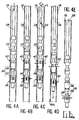
- les figures 4A à 4E sont des vues en coupe partielle schématique illustrant successivement la descente de l'outil de coupe selon l'invention dans le tubage, l'ancrage de cet outil, la découpe d'un tronçon inférieur de ce tubage, la descente de ce tronçon jusqu'à l'extrémité inférieure du cuvelage, puis le largage de ce tronçon dans la cavité ;
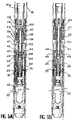
- les figures 5A et 5B sont des vues en coupe représentant à plus grande échelle les moyens d'ancrage situés dans la partie inférieure de l'outil de coupe, respectivement dans leur position escamotée et dans leur position d'ancrage ;
- les figures 6A et 6B sont des vues en coupe illustrant à la même échelle que les figures 5A et 5B la partie supérieure de l'outil de coupe dans laquelle sont logés les moyens de coupe, ces derniers étant illustrés respectivement en position escamotée et en position de coupe ;
- les figures 7A et 7B sont des vues en coupe illustrant à plus grande échelle les moyens de déconnexion par lesquels l'outil de coupe est normalement suspendu à l'extrémité inférieure du train de tiges, ces moyens de déconnexion étant illustrés respectivement dans leur position normale de liaison et dans leur position de déconnexion ; et
- la figure 8 est une vue développée représentant un barillet rotatif monté dans le piston commandant les moyens d'ancrage, illustrant différentes positions relatives entre ce barillet et des pions portés par la partie inférieure non rotative de l'outil.
- Figure 1, already described, is a sectional view illustrating very schematically the filling with gas of a salt cavity filled with brine;
- Figure 2, already described, is a sectional view comparable to Figure 1 illustrating a well allowing, in the current state of the art, to exploit a saline natural gas storage cavity;
- Figure 3 is a sectional view comparable to Figure 2 illustrating very schematically a well for exploiting a saline cavity after the tubing of this well has been removed according to the method of the invention;
- FIGS. 4A to 4E are schematic partial section views successively illustrating the descent of the cutting tool according to the invention into the casing, the anchoring of this tool, the cutting of a lower section of this casing, the descent from this section to the lower end of the casing, then dropping this section into the cavity;
- Figures 5A and 5B are sectional views showing on a larger scale the anchoring means located in the lower part of the cutting tool, respectively in their retracted position and in their anchoring position;
- FIGS. 6A and 6B are sectional views illustrating on the same scale as FIGS. 5A and 5B the upper part of the cutting tool in which the cutting means are housed, the latter being illustrated respectively in the retracted position and in the position cutting;
- FIGS. 7A and 7B are sectional views illustrating on a larger scale the disconnection means by which the cutting tool is normally suspended from the lower end of the drill string, these disconnection means being illustrated respectively in their normal connection position and in their disconnection position; and
- Figure 8 is a developed view showing a rotary barrel mounted in the piston controlling the anchoring means, illustrating different relative positions between this barrel and the pins carried by the non-rotating lower part of the tool.
Conformément à l'invention, afin d'éliminer le tubage 18 sur toute sa longueur, à l'exception de la partie supérieure d'environ 100 m dans laquelle sont situées les vannes de sécurité 24 (figure 2) on utilise un outil de coupe équipé de moyens d'ancrage à commande séparée, que l'on descend dans le tubage 18 afin de découper ce dernier, en partant du bas, en tronçons qui restent fixés à l'outil par les moyens d'ancrage après la découpe, de telle sorte que chaque tronçon découpé soit descendu en dessous de l'extrémité inférieure du cuvelage 14, avant d'être largué dans la cavité saline. En répétant ces opérations autant de fois que nécessaire, le puits servant à exploiter la cavité saline se trouve dans les conditions illustrées sur la figure 3, c'est-à-dire que la majeure partie du tubage 18, découpé en tronçons 18a, repose dans le fond de la cavité saline 21, à l'exception de la partie supérieure du tubage dans laquelle se trouvent les vannes de sécurité 24. Dans ces conditions, l'exploitation de la cavité saline se caractérise par un gain sur le débit de soutirage du gaz stocké pouvant atteindre jusqu'à environ 68 % par rapport à la configuration actuelle illustrée sur la figure 2.According to the invention, in order to eliminate the
Pour effectuer ces différentes opérations, le dispositif d'élimination du tubage conforme à l'invention comprend une installation de surface (non représentée) au moyen de laquelle un train de tiges tubulaires 28 (figures 4A à 4E) portant à son extrémité inférieure un outil de coupe 30 est introduit dans le tubage 18.To perform these various operations, the casing disposal device according to the invention comprises a surface installation (not shown) by means of which a train of tubular rods 28 (FIGS. 4A to 4E) carrying at its lower end a tool cutting 30 is introduced into the
L'installation de surface permet de réaliser la montée et la descente du train de tiges 28, ainsi que son entraînement en rotation. Le train de tiges 28 est formé à cet effet de tiges tubulaires élémentaires, appelées "macaronis", qui sont vissées bout à bout au fur et à mesure de la descente de l'outil et qui sont dévissées lors de sa remontée. Cette installation de surface, appelée installation de "repoussage" (en anglais, "snubbing") est une installation connue qui permet à tout moment de garantir l'étanchéité entre le train de tiges et l'intérieur du tubage dans lequel ce dernier pénètre. Cette installation comprend des vérins hydrauliques qui, par l'intermédiaire de coins d'ancrage, permettent de forcer le train de tiges à pénétrer dans le puits sous pression au début de la descente, et de le retenir à l'encontre de son poids à la fin de la descente. Elle permet en outre d'entraîner le train de tiges en rotation, de le remplir d'eau et d'appliquer à volonté des impulsions de pression sur la colonne d'eau ainsi formée.The surface installation allows the ascent and descent of the
En se référant à la figure 4A, on voit que l'outil de coupe 30 est monté à l'extrémité inférieure du train de tiges 28 par l'intermédiaire de moyens de déconnexion 32 qui seront décrits en détail par la suite en se référant aux figures 7A et 7B. L'outil de coupe 30 comprend une partie inférieure non rotative 34 dans laquelle sont logés des moyens d'ancrage 36 et une partie supérieure rotative 38 dans laquelle sont logés des moyens de coupe 40. La partie inférieure 34 est prévue pour être ancrée à l'intérieur du tubage 18 à l'aide des moyens d'ancrage 36, de façon à être immobilisés en rotation et en translation dans le tubage. Au contraire, la partie supérieure 38 est fixée au train de tiges 28 par l'intermédiaire des moyens de déconnexion 32, de façon à pouvoir tourner librement par rapport à la partie inférieure 34.Referring to FIG. 4A, it can be seen that the cutting
Avant de procéder à la description détaillée de l'outil de coupe 30, on décrira brièvement les différentes opérations qui sont mises en oeuvre pour éliminer le tubage 18, en se référant successivement aux figures 4A à 4E.Before proceeding to the detailed description of the
Une première opération (non représentée sur les figures), consiste à couper à l'aide d'un outillage quelconque (par exemple à explosif) la partie inférieure du tubage 18 comportant la vanne de circulation 22 et située en dessous de l'extrémité inférieure du cuvelage 14. On installe alors des manchons de protection (non représentés) à l'intérieur des vannes de sécurité 24.A first operation (not shown in the figures) consists in cutting using any tool (for example explosive) the lower part of the
On descend ensuite progressivement, à l'aide de l'installation de surface, l'outil de coupe 30 après l'avoir fixé à l'extrémité inférieure du train de tiges tubulaires 28 jusqu'à un niveau correspondant à la première découpe à effectuer, à la partie inférieure du tubage 18 (figure 4A). Pendant la descente, les moyens d'ancrage 36 ainsi que les moyens de coupe 40 occupent leur position escamotée de repos. De plus, au fur et à mesure de la descente, le train de tiges 28 est rempli d'eau.The cutting
Lorsque la cote désirée est atteinte par l'outil, les moyens d'ancrage 36 sont actionnés par l'envoi d'un signal de pression au travers de la colonne de liquide remplissant le train de tiges 28, d'une manière qui sera décrite en détail par la suite. La partie inférieure 34 de l'outil se trouve alors solidarisée en rotation et en translation du tubage 18 (figure 4B). Dans ces conditions, un effort de traction par exemple de 2 tonnes est exercé sur le train de tiges 28, afin de contrôler la bonne tenue des moyens d'ancrage. La valeur de cet effort de traction est choisie afin de correspondre au poids qu'auront à retenir les moyens d'ancrage après la coupe, ce qui évite tout risque de largage prématuré du tronçon coupé à ce moment.When the desired dimension is reached by the tool, the anchoring means 36 are actuated by sending a pressure signal through the column of liquid filling the train of
L'opération de coupe peut ensuite être débutée (figure 4C), en mettant en rotation depuis la surface la partie supérieure 38 de l'outil, au travers du train de tiges 28 et des moyens de déconnexion 32 (flèche F1). A cette mise en rotation de la partie supérieure 38 de l'outil s'ajoute dans un deuxième temps l'application d'un effort orienté vers le bas (flèche F2) correspondant à environ 1 tonne de poids sur les moyens d'ancrage 36. Les couteaux 42 des moyens de coupe 40 s'écartent alors et attaquent le tubage sous l'effet de la rotation de la partie supérieure 38 de l'outil.The cutting operation can then be started (FIG. 4C), by rotating the
Lorsque la coupe est terminée, comme l'illustre la figure 4D, le couple de rotation exercé sur le train de tiges chute et le poids de l'ensemble du dispositif est augmenté du poids du tronçon 18a découpé dans le tubage 18. Ces changements sont observés en surface et permettent aux opérateurs d'entamer la descente de l'ensemble formé par le train de tiges 28, l'outil 30 et le tronçon coupé 18a, jusqu'à l'extrémité inférieure du cuvelage entourant le tubage 18.When the cut is complete, as illustrated in FIG. 4D, the torque exerted on the drill string drops and the weight of the entire device is increased by the weight of the
Lorsque ce niveau est atteint et comme l'illustre la figure 4E, un nouveau signal de pression est envoyé dans la colonne d'eau contenue dans le train de tiges 28, ce qui a pour effet de commander le retour en position escamotée des moyens d'ancrage 36 et, par conséquent, le largage du tronçon coupé 18a.When this level is reached and as illustrated in FIG. 4E, a new pressure signal is sent to the water column contained in the
Un module inférieur d'ancrage de l'outil de coupe 30, comportant les moyens d'ancrage 36, va à présent être décrit en détail en se référant aux figures 5A et 5B.A lower module for anchoring the
Ce module inférieur d'ancrage comprend un corps tubulaire 41 fermé à son extrémité inférieure et constituant la portion basse de la partie inférieure non rotative 34. Dans sa partie centrale, le corps tubulaire 41 constitue le cylindre d'un vérin d'actionnement des moyens d'ancrage 36. Ce vérin comprend de plus un piston 44 qui coulisse de façon étanche à l'intérieur du corps tubulaire 41 et délimite dans ce dernier une chambre supérieure 46 et une chambre inférieure 48.This lower anchoring module comprises a
Le piston 44 est traversé par un alésage axial 45 dans lequel débouche au moins un passage 47 formé dans le piston et reliant l'alésage 45 à la chambre supérieure 46.An axial bore 45 passes through the
Un passage 50 formé dans le corps tubulaire 41 assure en permanence une communication entre la chambre inférieure 48 et une chambre fermée 52 formée dans la partie inférieure du corps tubulaire 41. Cette chambre 52 est séparée de l'alésage dans lequel est reçu le piston 44 par un bouchon étanche vissé 53.A
La chambre 52 est remplie d'un gaz sous pression tel que de l'azote par un orifice de remplissage (non représenté), avant que l'outil de coupe ne soit descendu dans le puits. La pression du gaz contenu dans la chambre 52 est déterminée de façon à être toujours supérieure d'au moins 50 bars à la pression hydrostatique de la colonne d'eau contenue dans le train de tiges auquel est suspendu l'outil de coupe. Ainsi, dans le cas d'un tubage long d'environ 1700 m correspondant à une pression maximum de la colonne d'eau dans la partie basse du tubage d'environ 170 bars, la pression de gaz dans la chambre 52 est égale à environ 220 bars. Par conséquent, le piston 44 est en permanence poussé vers le haut avec une force au moins égale à environ 1 tonne.
Dans sa partie supérieure, le piston 44 est solidaire, par l'intermédiaire de pions 54 traversant une partie de diamètre extérieur réduit du corps tubulaire 41 au-dessus de la chambre 46, d'une pièce annulaire 56 apte à coulisser axialement sur cette partie de diamètre extérieur réduit. La pièce annulaire 56 comporte une rampe tronconique 58 à son extrémité supérieure. La rampe tronconique 58 forme par exemple avec l'axe de l'outil un angle d'environ 15°.In its upper part, the
Des pièces d'ancrage 60, par exemple au nombre de trois, sont régulièrement réparties autour de la partie de diamètre extérieur réduit du corps tubulaire 41 au-dessus de la pièce 56. Chacune de ces pièces d'ancrage 60 est en appui sur la rampe tronconique 58 par une rampe complémentaire 62 et peut se déplacer radialement sur le corps tubulaire 41 entre une position escamotée illustrée sur la figure 5A et une position d'ancrage illustrée sur la figure 5B, à l'encontre de ressorts à lames 64 fixés sur le corps tubulaire 41. La surface extérieure des pièces d'ancrage 60 est cylindrique et irrégulière, de façon à éviter tout risque de glissement relatif entre ces pièces d'ancrage et le tubage 18 lorsque les pièces sont en appui contre la surface intérieure du tubage.
Dans sa partie située en dessous de la chambre inférieure 48 du vérin, le piston 44 supporte un barillet rotatif 66 qui présente sur sa surface extérieure une rainure 68 dans laquelle pénètrent deux pions 70 diamétralement opposés fixés radialement dans la pièce tubulaire 41.In its part located below the
Comme l'illustre la figure 8, la rainure 68 formée sur la surface extérieure du barillet rotatif 66 présente en développé une forme telle qu'à chaque déplacement axial relatif entre le piston 44 et le corps tubulaire formant la partie inférieure 34, le barillet 66 effectue une rotation dans un sens déterminé schématisé par la flèche F sur la figure 8, par suite de la coopération des pions 70 avec cette rainure 68.As illustrated in FIG. 8, the
De façon plus précise, la rainure 68 est réalisée de telle sorte qu'on puisse faire passer les moyens d'ancrage de leur position escamotée illustrée sur la figure 5A dans leur position d'ancrage illustrée sur la figure 5B et inversement, à chaque fois qu'une impulsion de pression est envoyée dans le train de tiges 28, chacune de ces positions étant maintenue par la coopération des pions 70 avec la rainure 68 lorsque cesse cette impulsion.More precisely, the
La position escamotée illustrée sur la figure 5A correspond à l'appui des pions 70 sur une partie de la rainure 68 fermée vers le bas, de la manière illustrée en 70-1 sur la figure 8.The retracted position illustrated in FIG. 5A corresponds to the support of the
Lorsqu'une impulsion de pression est envoyée dans le train de tiges 28 depuis la surface, cette impulsion parvient dans la chambre supérieure 46 au travers du passage 47 traversant le piston 44. La pression dans la chambre supérieure 46 devient alors supérieure à la pression dans la chambre inférieure 48, de sorte que le piston 44 se déplace vers le bas, à l'intérieur du corps tubulaire 41. Au cours de ce déplacement, les pions 70 viennent en appui sur des bords supérieurs inclinés 68-1 de la rainure 68, ce qui a pour effet d'entraîner en rotation le barillet 66 dans le sens de la flèche F, jusqu'à ce que les pions parviennent aux positions 70-2 illustrées sur la figure 8, correspondant à des parties de la rainure 68 fermées vers le haut.When a pressure pulse is sent into the
Dès que l'impulsion de pression envoyée dans le train de tiges cesse, la pression dans la chambre inférieure 48 redevient supérieure à la pression dans la chambre supérieure 46, de sorte que le piston 44 remonte à l'intérieur du corps tubulaire 41. Le piston 44 entraîne avec lui le barillet rotatif 66, de sorte que les pions 70 viennent en appui contre des bords inférieurs inclinés 68-2 de la rainure 68. Cela a pour effet de faire tourner à nouveau le barillet 66 dans le sens de la flèche F, jusqu'à ce que les pions 70 se trouvent en face de parties 68-3, orientées parallèlement à l'axe de l'outil et ouvertes vers le bas de la rainure 68. En pénétrant dans ces parties 68-3 de la rainure 68, les pions 70 permettent au piston 44 de remonter sur une distance suffisante pour que les pièces d'ancrage 60 viennent en appui contre la surface intérieure du tube 18. Les pions occupent alors les positions illustrées en 70-3 sur la figure 8.As soon as the pressure pulse sent to the drill string ceases, the pressure in the
Si une nouvelle impulsion de pression est envoyée dans le train de tiges 28, la pression dans la chambre supérieure 46 redevient momentanément supérieure à la pression régnant dans la chambre inférieure 48. Par conséquent, le piston 44 redescend à l'intérieur du corps tubulaire 41. Il entraîne avec lui le barillet rotatif 66, de telle sorte que les pions 70 viennent en appui contre des bords supérieurs inclinés 68-4 de la rainure 68. L'inclinaison de ces bords 68-4 a encore pour effet de faire tourner le barillet 66 dans le sens de la flèche F, jusqu'à ce que les pions 70 se trouvent dans les positions illustrées en 70-4 sur la figure 8, correspondant à des parties de la rainure 68 fermées vers le haut.If a new pressure pulse is sent into the
Dès que cesse l'impulsion de pression, la pression dans la chambre supérieure 46 redevient inférieure à la pression dans la chambre inférieure 48, de sorte que le piston 44 remonte à l'intérieur du corps tubulaire 41. Le piston 44 entraîne dans son mouvement le barillet 66, de telle sorte que les pions 70 viennent en appui contre des bords inférieurs inclinés 68-5 de la rainure 68. L'inclinaison de ces bords 68-5 a encore une fois pour effet de faire tourner le barillet 66 dans le sens de la flèche F, jusqu'à ce que les pions 70 reviennent dans leur position initiale illustrée en 70-1 sur la figure 8. Dans ces conditions, les pièces d'ancrage 60 restent dans leur position escamotée bien que la pression dans la chambre supérieure 46 soit inférieure à la pression dans la chambre inférieure 48.As soon as the pressure pulse ceases, the pressure in the
Par conséquent, la coopération du barillet rotatif 66 avec les pions 70 permet, en envoyant des impulsions de pression dans la colonne d'eau qui remplit le train de tiges 28, de faire passer alternativement les pièces d'ancrage 60 de leur position escamotée dans leur position d'ancrage, et inversement.Therefore, the cooperation of the
On décrira à présent en se référant aux figures 6A et 6B le module supérieur de coupe de l'outil, dans lequel sont logés les moyens de coupe 40.A description will now be given with reference to FIGS. 6A and 6B of the upper cutting module of the tool, in which the cutting means 40 are housed.
Le module supérieur de coupe comprend un corps tubulaire extérieur 71 pourvu à son extrémité inférieure d'un filetage 71a normalement vissé dans un taraudage 41a formé à l'extrémité supérieure du corps tubulaire 41 (figure 5A). Les corps tubulaires 41 et 71 forment, lorsqu'ils sont assemblés, la partie inférieure non rotative 34 de l'outil de coupe.The upper cutting module comprises an outer
Un corps tubulaire intérieur 72, formant la partie supérieure rotative 38 de l'outil, est monté dans le corps tubulaire extérieur 71 de façon à pouvoir tourner librement à l'intérieur de ce dernier et à pouvoir se déplacer selon l'axe de l'outil avec une course réduite. Cette course est limitée vers le haut par la venue en appui d'une partie centrale 72a de relativement grand diamètre du corps tubulaire intérieur 72 contre un épaulement supérieur 74 formé dans le corps tubulaire extérieur 71. La partie centrale 72a peut également venir en appui, par l'intermédiaire d'une butée à billes 76 montée sur sa face inférieure, contre un épaulement inférieur 78 formé dans le corps tubulaire extérieur 71 et limitant le déplacement vers le bas du corps tubulaire intérieur 72.An inner
Un ressort de compression précontraint 80 est monté dans un espace annulaire formé entre la partie supérieure du corps tubulaire extérieur 71 et une partie supérieure 72b de relativement petit diamètre du corps tubulaire intérieur 72. Ce ressort de compression 80 prend appui par son extrémité inférieure sur un épaulement du corps tubulaire extérieur 71, par l'intermédiaire d'une butée à billes 82. L'extrémité supérieure du ressort 80 est en appui direct contre la face inférieure de trois pièces 84 montées coulissantes dans des rainures axiales 85 formées dans la partie supérieure 72b du corps tubulaire intérieur 72 et régulièrement réparties. Sous l'action du ressort 80, un talon formé à l'extrémité inférieure de chaque pièce 84 est normalement en appui contre un épaulement 86, tourné vers le bas, formé à l'intérieur du corps tubulaire extérieur 71. L'extrémité supérieure de chacune des pièces 84 fait saillie au-delà du bord d'extrémité supérieur du corps tubulaire 71.A
La face supérieure de chaque pièce 84 présente une rampe inclinée 88 sur laquelle est normalement en appui le talon d'un couteau 90 logé dans la même rainure axiale 85 que cette pièce 84 et monté pivotant sur la partie supérieure du corps intérieur tubulaire 72, au-dessus de la pièce 84. Les couteaux 90, qui sont avantageusement des couteaux Bowen Tools, Inc., sont montés pivotant sur le corps 72 par leur extrémité supérieure, au moyen d'un axe 92 orthogonal à l'axe de l'outil. Le talon formé à l'extrémité inférieure de chacun des couteaux 90 est maintenu en permanence en appui contre la rampe 88 correspondante par un ressort à lame 94 fixé sur le corps tubulaire intérieur 72. L'extrémité inférieure de chaque couteau 90 comporte également une arête tranchante 90a tournée vers l'extérieur.The upper face of each
L'agencement qui vient d'être décrit permet aux couteaux 90 d'occuper normalement une position rétractée, illustrée sur la figure 6A, sous l'action des ressorts à lame 94, lorsque le corps tubulaire intérieur 72 occupe sa position haute à l'intérieur du corps tubulaire extérieur 71. Au contraire, comme l'illustre la figure 6B, lorsque le corps tubulaire intérieur 72 occupe sa position basse à l'intérieur du corps tubulaire extérieur 71, la coopération entre les talons des couteaux 90 et les rampes 88 a pour effet d'écarter les couteaux 90 à l'encontre des ressorts à lame 94, dans une position de coupe dans laquelle les arêtes tranchantes des couteaux 90 sont appliquées contre la surface intérieure du tubage 18 avec un effort de coupe déterminé par la précontrainte emmagasinée dans le ressort 80. Cette précontrainte peut notamment être d'environ 600 daN et reste indépendante de l'effort appliqué par ailleurs sur le corps tubulaire intérieur 72.The arrangement which has just been described allows the
En dessous de la partie centrale 72a, le corps tubulaire intérieur 72 comporte une partie inférieure 72c de relativement petit diamètre, terminée par un filetage 96 dont les filets comportent une face supérieure inclinée et une face inférieure droite. Lorsque le corps tubulaire intérieur 72 est dans la position haute illustrée sur la figure 6A, ce filetage 96 est vissé dans un écrou segmenté 98 constitué, par exemple, de quatre segments sollicités élastiquement vers l'intérieur par des anneaux élastiques 100. Cet écrou segmenté 98 est immobilisé en translation à l'intérieur du corps tubulaire extérieur 71 et comporte des filets complémentaires des filets formant le filetage 96.Below the
Le système ainsi formé constitue un filetage unidirectionnel qui empêche tout déplacement vers le bas du corps tubulaire intérieur 72 à l'intérieur du corps tubulaire extérieur 71 lorsqu'aucune rotation du corps tubulaire intérieur dans le sens du vissage n'intervient. Au contraire, ce filetage unidirectionnel permet au corps tubulaire intérieur 72 de revenir dans sa position haute sous l'effet d'un simple effort axial orienté vers le haut, sans qu'il soit nécessaire de faire tourner ce corps tubulaire intérieur en sens inverse.The system thus formed constitutes a unidirectional thread which prevents any downward movement of the inner
Lorsque l'outil de coupe est descendu dans le puits, les couteaux 90 occupent la position escamotée illustrée sur la figure 6A et le filetage 96 formé à l'extrémité inférieure du corps tubulaire intérieur 72 est vissé dans l'écrou segmenté 98. Tout écartement intempestif des couteaux 90 est alors empêché.When the cutting tool is lowered into the well, the
Lorsque les corps tubulaires 41 et 71, formant la partie inférieure 34 de l'outil sont immobilisés à l'intérieur du tubage 18 après l'actionnement des moyens d'ancrage 36, la découpe du tubage est effectuée en entraînant en rotation le corps tubulaire intérieur 72 au moyen de l'installation de surface reliée à ce corps par le train de tiges 28. Cette rotation a pour effet de visser le filetage 96 dans l'écrou segmenté 98 et, par conséquent, de faire descendre le corps tubulaire intérieur 72 dans le corps tubulaire extérieur 71. Au cours de cette descente, les couteaux 90, poussés par les rampes 88, s'écartent et viennent en contact avec le tubage 18 à couper. Le mouvement de rotation transmis au corps tubulaire intérieur 72 s'accompagne de l'application progressive d'un effort correspondant à un poids d'environ 1 à 1,5 tonne. Cet effort, qui assure la poursuite de la descente du corps tubulaire intérieur 72 nécessaire à la découpe lorsque le filetage 96 n'est plus en prise avec l'écrou segmenté 98, n'est pas transmis aux couteaux 90. Comme on l'a déjà mentionné, l'effort exercé sur ces couteaux est essentiellement déterminé par la force emmagasinée dans le ressort 80, qui assure l'application d'un effort de coupe sensiblement constant sur les couteaux.When the
Lorsque la descente en hélice des couteaux 90 obtenue de la manière qui vient d'être décrite amène la partie centrale 72a du corps tubulaire intérieur 72 en appui contre l'épaulement 78 par l'intermédiaire de la butée à bille 76, la coupe est terminée.When the helical descent of the
Il est à noter que dans certains cas, il est possible d'injecter de l'eau dans l'espace annulaire formé entre le tubage 18 et le train de tiges 28, pour assurer la lubrification des couteaux 90 lors de la coupe et faciliter cette dernière.It should be noted that in some cases it is possible to inject water into the annular space formed between the
Lorsque la coupe est terminée, l'effort axial et l'effort de rotation appliqués sur le corps tubulaire intérieur 72 par l'intermédiaire du train de tiges sont interrompus. En exerçant alors sur le train de tiges un effort orienté vers le haut qui s'ajoute à l'action des ressorts à lames 94, on permet aux couteaux 90 de reprendre leur position escamotée illustrée sur la figure 6A, grâce au filetage unidirectionnel constitué par le filetage 96 et l'écrou segmenté 98.When the cut is finished, the axial force and the rotational force applied to the inner
Etant donné que la pression du gaz dans le tubage ainsi que la pression hydrostatique de l'eau dans le train de tiges sont variables, l'outil de coupe est en outre conçu de façon à être indépendant des fluctuations de pression inhérentes aux conditions opératoires. A cet effet, on s'arrange pour que toutes les sections sur lesquelles s'appliquent la pression du gaz contenu dans le tubage ainsi que la pression de la colonne d'eau contenue dans le train de tiges soient égales et en équilibre.Since the pressure of the gas in the casing as well as the hydrostatic pressure of the water in the drill string are variable, the cutting tool is further designed so as to be independent of the pressure fluctuations inherent in the operating conditions. To this end, arrangements are made so that all the sections to which the pressure of the gas contained in the casing as well as the pressure of the water column contained in the drill string apply are equal and in equilibrium.
A cet effet, trois séries de joints tournants désignés respectivement par les références 128, 130 et 132 sont placés entre le corps tubulaire intérieur 72 et le corps tubulaire extérieur 71 (figures 6A et 6B). Les joints tournants 130 sont placés entre le corps tubulaire extérieur 71 et la partie centrale 72a de relativement grand diamètre du corps tubulaire intérieur 72 et les joints tournants 128 et 132 sont placés respectivement entre les parties supérieure 72b et inférieure 72c du corps tubulaire intérieur 72 et le corps tubulaire extérieur 71, à proximité de la partie centrale 72a. De plus, les sections des parties 72b et 72c sur lesquelles sont placés les joints tournants 128 et 132 sont égales entre elles, ainsi qu'à la différence de section entre la partie centrale 72a et ces parties 72b et 72c.To this end, three series of rotary joints respectively designated by the
Par ailleurs, le corps tubulaire extérieur comporte au moins une perforation 134 débouchant entre les joints tournants 130 et 132 et au moins une perforation 136 débouchant au-dessus des joints tournants 128, dans la chambre annulaire contenant le ressort 80. De même, le corps tubulaire intérieur 72 comporte au moins une perforation 138 débouchant entre les joints tournants 128 et 130.Furthermore, the outer tubular body has at least one
Par conséquent, le gaz contenu dans le tubage 18 agit sur des surfaces opposées et égales du corps tubulaire intérieur 72 formées par la partie supérieure 72b située au-dessus des joints toriques 128 et par la surface inférieure annulaire de la partie centrale 72a. De façon comparable, la pression de la colonne d'eau à l'intérieur du train de tiges 28 agit simultanément sur les surfaces opposées et égales formées par la surface annulaire supérieure de la partie centrale 72a et par la partie de ce corps tubulaire située en dessous des joints toriques 132.Consequently, the gas contained in the
Ces différentes caractéristiques permettent de faciliter la rotation et la translation du corps tubulaire intérieur 72 à l'intérieur du corps tubulaire extérieur 71, indépendamment des fluctuations des pressions.These various characteristics make it possible to facilitate the rotation and the translation of the inner
En outre, on s'arrange lors de la coupe d'un tronçon du tubage 18 pour que la pression de l'eau dans le train de tiges soit maintenue aussi proche que possible de celle du gaz dans le tubage, tout en restant inférieure à la pression d'azote régnant dans la chambre fermée 52.In addition, arrangements are made when cutting a section of the
L'outil de coupe illustré sur les figures comprend de plus un moyen permettant de commander le relâchement des moyens d'ancrage 36, dans le cas où le système décrit précédemment en se référant aux figures 5A et 5B ne fonctionnerait pas.The cutting tool illustrated in the figures further comprises a means for controlling the release of the anchoring means 36, in the case where the system previously described with reference to Figures 5A and 5B would not work.
Ce moyen de relâchement de secours, illustré sur les figures 5A et 5B, comprend une tige tubulaire coulissante 102 reçue dans le piston 44 selon l'axe de l'outil et dont la partie supérieure fait saillie au-delà du bord supérieur du piston 44. Cette tige tubulaire 102 est normalement immobilisée à l'intérieur du piston 44 par une goupille frangible 103, dans une position dans laquelle une partie inférieure 108 de cette tige obture de façon étanche l'alésage 45 formé dans le piston 44, entre le passage 47 débouchant dans la chambre supérieure 46 et un passage 49 débouchant dans la chambre inférieure 48. Dans cette même position, une autre partie 104 de la tige tubulaire 102 obture de façon étanche l'alésage 45 en dessous du passage 49.This emergency release means, illustrated in FIGS. 5A and 5B, comprises a sliding
Lorsqu'on se trouve dans la position d'ancrage illustrée sur la figure 5B et qu'il n'est pas possible de repasser à la position escamotée illustrée sur la Figure 5A par l'envoi d'une impulsion de pression dans le train de tiges, ce qui peut notamment se produire si une fuite apparaît dans le train de tiges, on peut obtenir le relâchement des moyens d'ancrage 36 en descendant à l'intérieur du train de tiges un outil tel qu'une barre de charge suspendue à un câble. Cet outil vient heurter l'extrémité supérieure de la tige tubulaire 102, ce qui a pour effet de casser la goupille frangible 103 et de faire descendre la tige à l'intérieur du piston 44. La partie 108 de la tige 102 descend alors en dessous du passage 49, ce qui a pour effet de faire communiquer les chambres 46 et 48 et d'égaliser les pressions agissant sur le piston 44. En continuant le battage de la tige 102 à l'aide de la barre de charge, la tige force le piston 44 à descendre en entraînant ainsi la pièce 56, ce qui a pour effet de ramener les blocs d'ancrage 60 dans leur position escamotée illustrée sur la figure 5A.When you are in the anchoring position illustrated in Figure 5B and it is not possible to return to the retracted position illustrated in Figure 5A by sending a pressure pulse in the train rods, which can in particular occur if a leak appears in the drill string, the loosening of the anchoring means 36 can be obtained by descending inside the drill string a tool such as a load bar suspended from a cable. This tool strikes the upper end of the
L'ensemble de l'outil peut alors être ramené en surface afin d'être contrôlé et réarmé.The entire tool can then be brought back to the surface to be checked and reset.
Comme l'illustrent les figures 7A et 7B, l'outil de coupe selon l'invention est avantageusement fixé à l'extrémité inférieure du train de tiges par l'intermédiaire de moyens de déconnexion 32 qui permettent de désolidariser l'outil du train de tiges dans le cas où aucun des systèmes décrits précédemment ne permettrait de relâcher les moyens d'ancrage.As illustrated in FIGS. 7A and 7B, the cutting tool according to the invention is advantageously fixed to the lower end of the drill string by means of disconnection means 32 which make it possible to separate the tool from the train of rods in the event that none of the systems described above would allow the anchoring means to be released.
Ces moyens de déconnexion 32 comprennent un corps tubulaire femelle 110 dont l'extrémité inférieure comporte un filetage 110a prévu pour être vissé dans un taraudage 71b formé à l'extrémité supérieure du corps tubulaire intérieur 72 illustré sur les figures 6A et 6B. Le corps tubulaire femelle 110 est accouplé à un corps tubulaire mâle 112 comportant à son extrémité supérieure un taraudage 112a dans lequel est vissée l'extrémité inférieure de la tige élémentaire adjacente du train de tiges 28.These disconnection means 32 comprise a female
Dans sa partie supérieure de moindre épaisseur, le corps tubulaire femelle 110 comporte une denture intérieure 114. Par ailleurs, le corps tubulaire mâle 112 comporte une partie inférieure de plus petit diamètre qui est reçue de façon étanche dans la partie supérieure de moindre épaisseur du corps tubulaire 110 et se termine par des branches souples et élastiques 116 dont les extrémités inférieures sont pourvues sur leur surface extérieure de dentures 118 complémentaires des dentures 114.In its upper part of lesser thickness, the female
Lorsque l'extrémité inférieure de plus petit diamètre du corps tubulaire mâle 112 est emmanchée dans l'extrémité supérieure de moindre épaisseur du corps tubulaire femelle 110, les dentures 114 et 118 sont normalement maintenues en prise par un manchon coulissant 120 monté dans le corps tubulaire mâle 112. Plus précisément, le manchon 120 comporte dans une partie centrale ajourée une nervure périphérique 122 normalement logée dans une gorge annulaire 124 formée à l'intérieur du corps tubulaire 112. Dans ces conditions, l'extrémité inférieure rigide de la bague de verrouillage 120 maintient les extrémités inférieures des branches souples 116 comportant les dentures 118 en prise contre les dentures 114.When the smaller diameter lower end of the male
Lorsqu'on désire déconnecter le corps tubulaire mâle 112 du corps tubulaire femelle 110, on descend à l'aide d'un câble un outil coulissant 126 illustré en traits discontinus sur la figure 7A. Cet outil 126, vient en appui contre un épaulement 125 formé dans la partie inférieure du manchon coulissant 120 et permet, par battage, de faire sortir la nervure circonférentielle 122 de la gorge annulaire 124 en déformant la partie centrale ajourée du manchon 120. Cette dernière descend alors à l'intérieur du corps tubulaire mâle 112, comme l'illustre la figure 78, de sorte que les extrémités inférieures des branches souples 116 sur lesquelles sont formées les dents 118 se trouvent en face d'une partie de plus petit diamètre du manchon 120 et peuvent donc se dégager des dentures 114 formées à l'intérieur de la pièce tubulaire femelle 110. La déconnexion est alors obtenue et le train de tiges portant le corps tubulaire 112 peut être remonté, alors que le corps tubulaire 110 lié à l'outil de coupe reste au fond du puits.When it is desired to disconnect the male
Il est à noter que les moyens de déconnexion qui viennent d'être décrits permettent, le cas échéant, de reconnecter le train de tiges à l'outil de coupe si la déconnexion est faite avant que la coupe ne soit réalisée. Au contraire, si la déconnexion intervient après la découpe d'un tronçon par l'outil, l'ensemble de l'outil de coupe est automatiquement largué dans la cavité et perdu.It should be noted that the disconnection means which have just been described make it possible, if necessary, to reconnect the drill string to the cutting tool if the disconnection is made before the cutting is carried out. On the contrary, if the disconnection occurs after the cutting of a section by the tool, the whole of the cutting tool is automatically dropped into the cavity and lost.
Bien entendu, l'invention n'est pas limitée au mode de réalisation qui vient d'être décrit à titre d'exemple, mais en couvre toutes les variantes.Of course, the invention is not limited to the embodiment which has just been described by way of example, but covers all its variants.
Ainsi, le module de déconnexion 32 peut dans certains cas être supprimé et la commande des pièces d'ancrage et des couteaux peut être différente de celle qui a été décrite.Thus, the
Claims (10)
- A method of removing a tubing (18) disposed coaxially inside a casing (14) in an access well (10) to a salt cavity (21) for storing gas, the method being characterized by the fact that it comprises the step of cutting the tubing (18) into lengths (18a) from the bottom up by performing the following operations:a) lowering a cutting tool (30) down the tubing;b) anchoring said tool inside the tubing below a selected cutting level;c) cutting the tubing mechanically by means of the cutting tool, thereby cutting off a bottom length from the tubing;d) lowering the tool holding said bottom length to below the bottom end of the casing;e) dropping the bottom length from the cutting tool;f) raising the cutting tool into the tubing up to a cutting level higher than the previous cutting level; andg) repeating operations b) to f) until the tubing has been cut up completely.
- Apparatus for removing a tubing (18) disposed coaxially inside a casing (14) inside an access well (10) to a salt cavity (21) for storing gas, the apparatus being characterized by the fact that it comprises a cutting tool (30) suitable for being lowered down the tubing at the end of a string of tubular rods (28), said cutting tubing comprising:- anchor means (36) for anchoring a non-rotary bottom portion (38) of the tool inside the tubing, the anchor means being actuated by varying the pressure inside the string of rods against a force exerted by return means (52); and- cutting means (40) including at least one knife (90) mounted on a rotary top portion (38) of the tool, with the knife being extended by displacing said top portion downwards relative to the bottom portion.
- Apparatus according to claim 2, characterized by the fact that the anchor means comprise a piston (44) movable along an axis of the tool inside said bottom portion, a top face of the piston being subjected to the pressure existing inside the string of rods, and a bottom face of the piston being subjected to the action of said return means (52), the piston being fixed to at least one annular part (56) co-operating with at least one anchor piece (60) to displace said anchor piece radially outwards against resilient means (64) when the piston moves upwards.
- Apparatus according to claim 3, characterized by the fact that the return means comprise a closed chamber (52) formed inside said bottom portion and filled with gas under pressure.
- Apparatus according to claim 4, characterized by the fact that the cutting tool includes a sliding rod (102) mounted inside the piston so as to be capable of taking up a high position in which said rod closes a passage (45) formed through the piston and suitable for putting the top and bottom faces of the piston into communication with each other, and a low position in which said passage is open, the sliding rod being normally held in its high position by a frangible member (103).
- Apparatus according to any one of claims 3 to 5, characterized by the fact that the piston (44) supports a rotary drum (66) provided with a groove (68) into which at least one peg (70) carried by said bottom portion penetrates, said groove being such that after a pressure pulse inside the string of rods, the anchor piece (56) is held in its extended position until a further pressure pulse is applied to the string of rods.
- Apparatus according to any one of claims 2 to 6, characterized by the fact that the rotary top portion of the tool is normally engaged with the non-rotary bottom portion by means of a one-way screw thread (96, 98) enabling said top portion to move downwards when rotated until it reaches a cutting bottom position in which said screw thread no longer meshes, with upwards displacement of said top portion being obtained merely by moving it in translation.
- Apparatus according to claim 7, characterized by the fact that the knife (90) bears against a ramp (88) formed on a part (84) mounted to slide parallel to the axis of the tool, with its opposite end bearing against the non-rotary bottom portion via prestressed resilient means (80).
- Apparatus according to any one of claims 2 to 8, characterized by the fact that the cutting tool (30) is suspended from the string of tubular rods (28) by remotely operable disconnection means (32).
- Apparatus according to claim 9, characterized by the fact that the disconnection means (32) comprise a male tubular body (112) fixed to the bottom end of the string of tubular rods, and including flexible branches (106) provided externally with indentations (118) complementary to indentations (114) formed in a female tubular body (110) fixed to the top end of the cutting tool, a sliding sleeve (120) normally held in a high position inside the male tubular body by locking means (122, 124) then holding the indentations formed on the flexible branches in engagement with the indentations formed in the female tubular body, the locking means being unlocked by applying a downwards force on the sliding sleeve (120) to move it to a low position in which the flexible branches (116) are free to deform radially inwardly, thereby disengaging the indentations formed on said branches from the indentations formed on the female tubular body.
Applications Claiming Priority (2)
| Application Number | Priority Date | Filing Date | Title |
|---|---|---|---|
| FR9004386A FR2660728B1 (en) | 1990-04-05 | 1990-04-05 | METHOD AND DEVICE FOR ELIMINATING A TUBING PROVIDED IN A WELL ACCESSING A SALINE CAVITY OF GAS STORAGE. |
| FR9004386 | 1990-04-05 |
Publications (2)
| Publication Number | Publication Date |
|---|---|
| EP0451058A1 EP0451058A1 (en) | 1991-10-09 |
| EP0451058B1 true EP0451058B1 (en) | 1994-06-22 |
Family
ID=9395479
Family Applications (1)
| Application Number | Title | Priority Date | Filing Date |
|---|---|---|---|
| EP19910400921 Expired - Lifetime EP0451058B1 (en) | 1990-04-05 | 1991-04-05 | Method and apparatus for discarding a tubing in an access well to a salt cavity for gas storage |
Country Status (3)
| Country | Link |
|---|---|
| EP (1) | EP0451058B1 (en) |
| DE (1) | DE69102571T2 (en) |
| FR (1) | FR2660728B1 (en) |
Families Citing this family (2)
| Publication number | Priority date | Publication date | Assignee | Title |
|---|---|---|---|---|
| US5732770A (en) * | 1996-08-02 | 1998-03-31 | Weatherford/Lamb, Inc. | Wellbore cutter |
| NO332901B1 (en) * | 2009-11-10 | 2013-01-28 | Norse Cutting & Abandonment As | Method and apparatus for closing a well in the ground |
Family Cites Families (6)
| Publication number | Priority date | Publication date | Assignee | Title |
|---|---|---|---|---|
| US2481637A (en) * | 1945-02-23 | 1949-09-13 | A 1 Bit & Tool Company | Combined milling tool and pipe puller |
| US3045752A (en) * | 1958-03-25 | 1962-07-24 | Baker Oil Tools Inc | Milling apparatus for removing objects from well bores |
| US3019840A (en) * | 1958-06-25 | 1962-02-06 | Thomas A Kennard | Retrieving tool |
| US3277654A (en) * | 1963-04-15 | 1966-10-11 | Phillips Petroleum Co | Underground storage caverns and method of making the same and of storing fluids therein |
| US4047568A (en) * | 1976-04-26 | 1977-09-13 | International Enterprises, Inc. | Method and apparatus for cutting and retrieving casing from a well bore |
| US4550781A (en) * | 1984-06-06 | 1985-11-05 | A-Z International Tool Company | Method of and apparatus for cutting and recovering of submarine surface casing |
-
1990
- 1990-04-05 FR FR9004386A patent/FR2660728B1/en not_active Expired - Lifetime
-
1991
- 1991-04-05 EP EP19910400921 patent/EP0451058B1/en not_active Expired - Lifetime
- 1991-04-05 DE DE1991602571 patent/DE69102571T2/en not_active Expired - Fee Related
Also Published As
| Publication number | Publication date |
|---|---|
| FR2660728B1 (en) | 1992-07-31 |
| DE69102571T2 (en) | 1995-02-09 |
| EP0451058A1 (en) | 1991-10-09 |
| DE69102571D1 (en) | 1994-07-28 |
| FR2660728A1 (en) | 1991-10-11 |
Similar Documents
| Publication | Publication Date | Title |
|---|---|---|
| EP1525371B1 (en) | Telescopic guide line for offshore drilling | |
| EP0265344B1 (en) | Method for producting a pile in the ground, drilling machine and device for carrying out such a method | |
| EP0689637B1 (en) | Method and device for cementing a well | |
| FR2958966A1 (en) | METHOD AND DEVICE FOR SEALING A WELL USING AN EXPANDABLE PLUG, PLUG FOR CARRYING OUT THE METHOD, AND EXTRACTOR TOOL FOR REMOVING IT | |
| WO1991000410A1 (en) | Device for guiding a drilling tool into a well and for exerting thereon a hydraulic force | |
| FR2519688A1 (en) | SEALING SYSTEM FOR DRILLING WELLS IN WHICH CIRCULATES A HOT FLUID | |
| FR2495704A1 (en) | HYDRAULIC DOUBLE EFFECT MECHANISM | |
| EP2417323B1 (en) | Locking device for a drilling device | |
| FR2814494A1 (en) | IMPROVED CORE BIT MOTOR AND METHOD FOR OBTAINING A CARROT SAMPLE OF MATERIAL | |
| FR2615897A1 (en) | LOCKING DEVICE FOR A TOOL IN A HYDROCARBON WELL | |
| CA1273286A (en) | Device for inserting a tool or an apparatus in a conduit for downhole exploitation of autonomous hydraulic pumps, in use for production through a tubing | |
| EP0321610B1 (en) | Oil well safety valve and setting and retrieving tools for such a valve | |
| FR2913228A1 (en) | Small circular orifice cutting and opening/closing device for recovering e.g. polluting effluent, has circular cutting unit disengaged from large orifice of base for opening small circular orifice when stopper is in open position | |
| EP0451058B1 (en) | Method and apparatus for discarding a tubing in an access well to a salt cavity for gas storage | |
| EP1259792B1 (en) | Method and device for driving into the marine subsurface at great depths, a tubular tool for soil sampling or for measuring soil characteristics | |
| EP0382607A1 (en) | Device for forming piles in the soil using a continuous hollow screw | |
| EP0165154B1 (en) | Method and device for effecting by means of specialized tools such operations as measurements in well sections highly inclined to the vertical, or the horizontals | |
| EP3414399B1 (en) | Method for producing an anchoring tie rod and anchoring tie rod | |
| EP0531336A1 (en) | Double-tube core drill for inclined drilling. | |
| FR2772826A1 (en) | Process for reinforcing at least part of the wall of a shaft | |
| WO2021048496A1 (en) | Method and device for large-diameter borehole or digging of wells following a plurality of inclinations | |
| EP0677437A1 (en) | Anti-surge method and device for marine structures | |
| FR2832454A1 (en) | VERTICAL WELL DRILLING EQUIPMENT | |
| WO2012140222A1 (en) | Method and device for nondestructive drilling | |
| FR2635129A1 (en) | Improvements to devices and methods for making concrete piles in the ground. |
Legal Events
| Date | Code | Title | Description |
|---|---|---|---|
| PUAI | Public reference made under article 153(3) epc to a published international application that has entered the european phase |
Free format text: ORIGINAL CODE: 0009012 |
|
| AK | Designated contracting states |
Kind code of ref document: A1 Designated state(s): DE GB IT NL |
|
| 17P | Request for examination filed |
Effective date: 19920404 |
|
| 17Q | First examination report despatched |
Effective date: 19930719 |
|
| GRAA | (expected) grant |
Free format text: ORIGINAL CODE: 0009210 |
|
| AK | Designated contracting states |
Kind code of ref document: B1 Designated state(s): DE GB IT NL |
|
| REF | Corresponds to: |
Ref document number: 69102571 Country of ref document: DE Date of ref document: 19940728 |
|
| ITF | It: translation for a ep patent filed |
Owner name: DOTT. FRANCO CICOGNA |
|
| GBT | Gb: translation of ep patent filed (gb section 77(6)(a)/1977) |
Effective date: 19940906 |
|
| PLBE | No opposition filed within time limit |
Free format text: ORIGINAL CODE: 0009261 |
|
| STAA | Information on the status of an ep patent application or granted ep patent |
Free format text: STATUS: NO OPPOSITION FILED WITHIN TIME LIMIT |
|
| 26N | No opposition filed | ||
| PGFP | Annual fee paid to national office [announced via postgrant information from national office to epo] |
Ref country code: DE Payment date: 19960603 Year of fee payment: 6 |
|
| PG25 | Lapsed in a contracting state [announced via postgrant information from national office to epo] |
Ref country code: DE Free format text: LAPSE BECAUSE OF NON-PAYMENT OF DUE FEES Effective date: 19980101 |
|
| REG | Reference to a national code |
Ref country code: GB Ref legal event code: IF02 |
|
| PG25 | Lapsed in a contracting state [announced via postgrant information from national office to epo] |
Ref country code: IT Free format text: LAPSE BECAUSE OF NON-PAYMENT OF DUE FEES;WARNING: LAPSES OF ITALIAN PATENTS WITH EFFECTIVE DATE BEFORE 2007 MAY HAVE OCCURRED AT ANY TIME BEFORE 2007. THE CORRECT EFFECTIVE DATE MAY BE DIFFERENT FROM THE ONE RECORDED. Effective date: 20050405 |
|
| PGFP | Annual fee paid to national office [announced via postgrant information from national office to epo] |
Ref country code: GB Payment date: 20100325 Year of fee payment: 20 |
|
| PGFP | Annual fee paid to national office [announced via postgrant information from national office to epo] |
Ref country code: NL Payment date: 20100402 Year of fee payment: 20 |
|
| REG | Reference to a national code |
Ref country code: NL Ref legal event code: V4 Effective date: 20110405 |
|
| REG | Reference to a national code |
Ref country code: GB Ref legal event code: PE20 Expiry date: 20110404 |
|
| PG25 | Lapsed in a contracting state [announced via postgrant information from national office to epo] |
Ref country code: NL Free format text: LAPSE BECAUSE OF EXPIRATION OF PROTECTION Effective date: 20110405 Ref country code: GB Free format text: LAPSE BECAUSE OF EXPIRATION OF PROTECTION Effective date: 20110404 |