EP0450860B2 - Methode zum Betrieb einer Gas-Flüssig-Blasenkolonne in Suspension - Google Patents
Methode zum Betrieb einer Gas-Flüssig-Blasenkolonne in Suspension Download PDFInfo
- Publication number
- EP0450860B2 EP0450860B2 EP91302710A EP91302710A EP0450860B2 EP 0450860 B2 EP0450860 B2 EP 0450860B2 EP 91302710 A EP91302710 A EP 91302710A EP 91302710 A EP91302710 A EP 91302710A EP 0450860 B2 EP0450860 B2 EP 0450860B2
- Authority
- EP
- European Patent Office
- Prior art keywords
- reactor
- liquid
- gas
- catalyst
- column
- Prior art date
- Legal status (The legal status is an assumption and is not a legal conclusion. Google has not performed a legal analysis and makes no representation as to the accuracy of the status listed.)
- Expired - Lifetime
Links
Images


Classifications
-
- C—CHEMISTRY; METALLURGY
- C10—PETROLEUM, GAS OR COKE INDUSTRIES; TECHNICAL GASES CONTAINING CARBON MONOXIDE; FUELS; LUBRICANTS; PEAT
- C10G—CRACKING HYDROCARBON OILS; PRODUCTION OF LIQUID HYDROCARBON MIXTURES, e.g. BY DESTRUCTIVE HYDROGENATION, OLIGOMERISATION, POLYMERISATION; RECOVERY OF HYDROCARBON OILS FROM OIL-SHALE, OIL-SAND, OR GASES; REFINING MIXTURES MAINLY CONSISTING OF HYDROCARBONS; REFORMING OF NAPHTHA; MINERAL WAXES
- C10G2/00—Production of liquid hydrocarbon mixtures of undefined composition from oxides of carbon
- C10G2/30—Production of liquid hydrocarbon mixtures of undefined composition from oxides of carbon from carbon monoxide with hydrogen
- C10G2/32—Production of liquid hydrocarbon mixtures of undefined composition from oxides of carbon from carbon monoxide with hydrogen with the use of catalysts
- C10G2/34—Apparatus, reactors
- C10G2/342—Apparatus, reactors with moving solid catalysts
-
- B—PERFORMING OPERATIONS; TRANSPORTING
- B01—PHYSICAL OR CHEMICAL PROCESSES OR APPARATUS IN GENERAL
- B01J—CHEMICAL OR PHYSICAL PROCESSES, e.g. CATALYSIS OR COLLOID CHEMISTRY; THEIR RELEVANT APPARATUS
- B01J8/00—Chemical or physical processes in general, conducted in the presence of fluids and solid particles; Apparatus for such processes
- B01J8/18—Chemical or physical processes in general, conducted in the presence of fluids and solid particles; Apparatus for such processes with fluidised particles
- B01J8/20—Chemical or physical processes in general, conducted in the presence of fluids and solid particles; Apparatus for such processes with fluidised particles with liquid as a fluidising medium
- B01J8/22—Chemical or physical processes in general, conducted in the presence of fluids and solid particles; Apparatus for such processes with fluidised particles with liquid as a fluidising medium gas being introduced into the liquid
-
- B—PERFORMING OPERATIONS; TRANSPORTING
- B01—PHYSICAL OR CHEMICAL PROCESSES OR APPARATUS IN GENERAL
- B01J—CHEMICAL OR PHYSICAL PROCESSES, e.g. CATALYSIS OR COLLOID CHEMISTRY; THEIR RELEVANT APPARATUS
- B01J2208/00—Processes carried out in the presence of solid particles; Reactors therefor
- B01J2208/00008—Controlling the process
- B01J2208/00725—Mathematical modelling
-
- Y—GENERAL TAGGING OF NEW TECHNOLOGICAL DEVELOPMENTS; GENERAL TAGGING OF CROSS-SECTIONAL TECHNOLOGIES SPANNING OVER SEVERAL SECTIONS OF THE IPC; TECHNICAL SUBJECTS COVERED BY FORMER USPC CROSS-REFERENCE ART COLLECTIONS [XRACs] AND DIGESTS
- Y02—TECHNOLOGIES OR APPLICATIONS FOR MITIGATION OR ADAPTATION AGAINST CLIMATE CHANGE
- Y02P—CLIMATE CHANGE MITIGATION TECHNOLOGIES IN THE PRODUCTION OR PROCESSING OF GOODS
- Y02P20/00—Technologies relating to chemical industry
- Y02P20/50—Improvements relating to the production of bulk chemicals
- Y02P20/582—Recycling of unreacted starting or intermediate materials
Definitions
- the present invention relates to the optimal operation of a slurry bubble column reactor.
- Such columns have three phases in which solid catalyst particles are held in suspension in a liquid phase by bubbling gas phase reactants.
- Slurry bubble column reactors operate by suspending catalytic particles in a liquid and feeding gas phase reactants into the bottom of the reactor through a gas distributor which produces small gas bubbles. As the gas bubbles rise through the reactor, the reactants are absorbed into the liquid and diffuse to the catalyst where, depending on the catalytic system, they can be converted to both liquid and gaseous products. If gaseous products are formed, they enter the gas bubbles and are collected at the top of the reactor. Liquid products are recovered by passing the slurry through a filter which separates the liquid from the catalytic solids.
- a principal advantage of slurry reactors over fixed bed reactors is that the presence of a circulating/agitated slurry phase greatly increases the transfer rate of heat to cooling surfaces built into the reactor.
- a distinct advantage of bubble columns over mechanically stirred reactors is that the required mixing is effected by the action of rising bubbles, a process significantly more energy-efficient than mechanical stirring.
- the rate of conversion of reactants to products and the product selectivity depend on the partial pressure of the reactants in contact with the catalyst.
- the mixing characteristics of the reactor become critical in determining catalyst performance because they will determine the gas phase composition (and therefore, the partial pressure of the reactants) at any particular axial position in the reactor.
- CSTR fully backmixed reactors
- the reactant concentration controls catalyst performance by providing the driving force for the reaction and determines the conversion occurring in the reactor.
- catalyst performance is driven by the uniform reactant gas phase concentration present throughout the reactor and equal to the reactant gas phase concentration exiting the reactor.
- the other extreme in reactor mixing occurs in plug flow reactors where the catalyst is stationary relative to the flow of reactants and products (liquids and gases).
- the feed undergoes reaction as it enters the reactor and the reaction continues as the unreacted feed proceeds through the reactor.
- the concentration and partial pressure of reactants decrease along the path of the reactor; therefore, the driving force of the reaction also decreases as the concentration of liquid and gaseous products increase.
- the catalyst at the exit portion of the plug flow reactor never sees fresh feed.
- the plug flow system provides maximum productivity for a given reactor volume for any reactions showing positive pressure order kinetics.
- the important difference between the CSTR and plug flow reactor systems is that the gas phase reactant concentrations that provide the kinetic driving force for the reaction differ significantly.
- the reactant concentration is the same at every point in the reactor; in the plug flow system, the reactant concentration steadily decreases along the path of the catalyst bed from inlet to outlet and the reaction rate is obtained by integrating the rate function from inlet to outlet. Because the reactant concentration at any point in a CSTR system always corresponds to outlet conditions, the productivity in a fully backmixed system will always be lower than the productivity in a plug-flow system for reactions with positive pressure order kinetics.
- Reactor systems exhibiting plug-flow and well stirred characteristics represent extremes in reactor performance.
- plug-flow reactors may exhibit some backmixed traits and backmixed reactors may exhibit some plug-flow traits. Deviations from the ideal systems are due to the dispersion of the reactant gases in the reactor. Extent of backmixing is a function of the mechanical energy imparted to the system.
- the reactor geometry also affects backmixing and small L/d (i.e., reactor length to reactor diameter) ratios, less than 3, favor complete backmixing. However, higher energy input reactors with greater L/d can also achieve complete backmixing. Conversely, plug-flow behavior is favored by high L/d ratios.
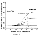
- the degree of backmixing that can occur in a plug-flow reactor can be represented by the Peclet number, Pe. (See Carberry, J.J., “Chemical and Catalytic Reaction Engineering”, McGraw-Hill, 1976, or Levenspiel, O., “Chemical Reaction Engineering”, Wiley, 1972.)
- Peclet numbers e.g., greater than 10
- low Peclet numbers e.g., less than 1
- the dispersion coefficient for an ideal CSTR is infinity and the Peclet number approaches zero.
- Optimum performance of slurry bubble column reactors requires adequate fluidization of the catalyst particles while minimizing backmixing of the reactants in the gas phase. If the conditions in the reactor are such that the particles settle, difficulties arise because the reaction zone is short. Then in order to achieve high conversions, the reaction rate per volume must be very high and the catalyst can easily become starved of reactants because of limitations in the rate at which reactants can be transferred from the gas bubbles to the particles suspended in the liquid. This condition results in poor catalyst utilization, poor reaction selectivity, and eventually to catalyst deactivation. Also, for exothermic reactions, the heat release takes place in the short reaction zone, imposing severe requirements on the heat transfer equipment.
- the tendency of the particles to settle can be overcome, however, by maximizing the dispersion effects resulting from the rising gas bubbles and from the mixing patterns that they induce. These dispersion effects can be enhanced by increasing either the effective reactor diameter or the flow rate of gas through the reactor. If the dispersion is increased too much, however, the gas phase will also become well mixed and the reactor performance will change from that of a plug flow reactor to that of a backmixed reactor.
- the embodiment of the present invention is the Fischer-Tropsch synthesis of hydrocarbon wax using Co catalysts.
- the Fischer-Tropsch reaction involves the catalytic hydrogenation of carbon monoxide to produce a variety of products ranging from methane to higher aliphatic alcohols.
- the methanation reaction was first described by Sabatier and Senderens in 1902.
- the later work by Fischer and Tropsch dealing with higher hydrocarbon synthesis (HCS) was described in Brennstoff-Chem, 7 , 97 (1926).
- the reaction is highly exothermic and care must be taken to design reactors for adequate heat exchange capacity as well as for their the ability to continuously produce and remove the desired range of hydrocarbon products.
- the process has been considered for the conversion of carbonaceous feedstocks, e.g., coal or natural gas, to higher value liquid fuel or petrochemicals.
- the first major commercial use of the Fischer-Tropsch process was in Germany during the 1930's. More than 1592 m 3 /day (10,000 B/D (barrels per day)) of products were manufactured with a cobalt based catalyst in a fixed-bed reactor. This work has been described by Fischer and Pichler in Ger. Pat. No. 731,295 issued August 2, 1936.
- the present invention is a method for optimally operating a three-phase slurry bubble column for the production of Fischer-Tropsch hydrocarbon synthesis wax as defined in claim 1.
- the optimal operation of a slurry bubble column reactor requires that the solid phase be fluidized in the liquid phase over the entire height of the column.
- the solid phase is fluidized by upward forces caused by rising gas bubbles and acting against the tendency of the particles to settle under the downward gravitational force.
- the catalyst powders employed in this invention comprise cobalt on an inorganic oxide support. These catalysts may contain additional promoters comprising Group I, Group II, Group V, or Group VII metals alone or in combination.
- the preferred catalyst powders of this invention comprise cobalt or cobalt and thoria on an inorganic oxide support containing a major amount of titania, silica or alumina.
- the catalyst may also contain a promoter metal, preferably rhenium, in an amount sufficient to provide a catalyst having a rhenium:cobalt weight ratio greater than about 0.01 to 1, preferably 0.025:1 to about 0.1 to 1.
- the catalyst contains about 2 to 50 wt% cobalt, preferably 5 to 20 wt% cobalt. ,
- the catalyst metals are supported on an inorganic refractory oxide comprising titania, silica or alumina.
- the support material is comprised of major amounts of titania and more preferably the titania has a rutile:anatase ratio of at least about 2:3 as determined by x-ray diffraction (ASTM D2730-78), preferably about 2:3 to about 100:1 or higher, more preferably about 4:1 to 100:1 or higher, e.g., 100% rutile.
- the surface area of the preferred support is, generally, less than about 50 m 2 /gm (BET).
- Cobalt-rhenium/titania catalysts exhibit high selectivity in the synthesis of hydrocarbon liquids from carbon monoxide and hydrogen.
- the catalysts employed in the practice of this invention may be prepared by techniques known in the art for the preparation of other catalysts.
- the catalyst powder can, e.g., be prepared by gellation, or cogellation techniques.
- the metals can be deposited on a previously pilled, pelleted, beaded, extruded, or sieved support material by the impregnation method.
- the metals are deposited from solution on the support in preselected amounts to provide the desired absolute amounts, and weight ratio of the respective metals, cobalt and rhenium.
- the cobalt and rhenium are composited with the support by contacting the support with a solution of a cobalt containing compound, or salt, or a rhenium-containing compound, or salt, e.g., a nitrate, carbonate or the like.
- a cobalt containing compound, or salt or a rhenium-containing compound, or salt, e.g., a nitrate, carbonate or the like.
- the cobalt and rhenium can be coimpregnated on the support.
- the cobalt and rhenium compounds used in the impregnation can be any organometallic or inorganic compounds which decompose upon heating in nitrogen, argon, helium or other inert gas, calcination in an oxygen containing gas, or treatment with hydrogen at elevated temperatures to give the corresponding metal, metal oxide, or mixtures of the metal and metal oxide phases, of cobalt and rhenium.
- Cobalt and rhenium compounds such as the nitrate, acetate, acetyl-acetonate, naphthenate, carbonyl, or the like can be used.
- the amount of impregnation solution should be sufficient to completely wet the carrier, usually within the range from about 1 to 20 times of the carrier by volume, depending on the metal, or metals, concentration in the impregnation solution.
- the impregnation treatment can be carried out under a wide range of conditions including ambient or elevated temperatures.
- the catalyst after impregnation, is dried by heating at a temperature above 30°C, preferably between 30°C and 125°C, in the presence of nitrogen, or oxygen, or both, or air, in a gas stream or under partial vacuum.
- the catalyst particles are converted to the desired particle size range of nominally greater than 30 to 200 microns average diameter by crushing, ultrasonic treatment, or other methods known to those skilled in the art.
- the material can then be sieved, if necessary, to produce a powder that is predominantly within the desired particle size range.
- the slurry liquid used in the process is a liquid at the reaction temperature, must be relatively or largely or significantly chemically inert under the reaction conditions and must be a relatively good solvent for CO/hydrogen and possess good slurrying and dispersing properties for the finely divided catalyst.
- hydrocarbon synthesis wax is used. (Most preferred really is HCS wax, i.e., the product of the FT reaction.)
- the height to which the catalyst can be fluidised is given by D/(U s -U L ) where D is the dispersion coefficient for the particles, U s is the particle settling velocity (see Example 2) and U L is the liquid velocity along the column.
- D the dispersion coefficient for the particles
- U s the particle settling velocity (see Example 2)
- U L the liquid velocity along the column.
- the total reactor volume must be controlled to yield the desired conversion rate of reactants to products for the intrinsic catalyst activity. This normally sets a minimum height for the reaction zone (i.e., minimum liquid and fluidization height) for economic reactor operation.
- a minimum height for the reaction zone i.e., minimum liquid and fluidization height
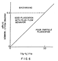
- catalyst particle diameter is greater than 30 microns.
- the flow regime has large gas slugs (i.e., slug flow) rising through the column rather than a dispersion of small gas bubbles typical of bubbly or churn turbulent flow which give better mass transfer performance.
- bubble column diameters of less than 10 cm should not be used for either obtaining data for scaleup or for commercial units (see Gas-Liquid-Solid Fluidization Engineering, Liang-Shih Fan, Butterworths, Boston (1989)). Reactors with small effective diameters also can lead to unreasonable complexity and construction cost when designed for systems large enough to convert commercial feed rates of reactants.
- V the reactor volume (V) required for a given exit concentration or conversion
- the required reactor volume is much less for the plug flow system at moderate or high conversions.
- a detailed model is available for calculating the effects of non-uniform catalyst distribution at intermediate mixing conditions for arbitrary kinetic expressions in specific applications.
- a given reactor generally exhibits behavior intermediate between plug-flow and well-mixed.
- Example 3 Experimental Procedure to Determine the Dispersion in a Given Reactor
- Example 2 demonstrates the importance of the Peclet number in determining the reactor performance. While calculating or measuring the reaction zone height and the gas velocity is relatively straightforward, it is difficult to know a priori the dispersion coefficient. The dispersion coefficient depends on the gas throughput velocity as well as on the reactor geometry. As the reactor diameter is increased, the dispersion increases rapidly. The problem is complicated by the need to provide internal reactor structures within the reactor in order to improve heat removal. A general correlation for the dispersion coefficient as a function of geometric configuration is not possible because different internal configurations will produce different and poorly understood mixing patterns. In fact, the geometry of the internal design is the key factor the designer can use to control the mixing behavior of a slurry bubble column reactor for a given outside diameter and height that are determined by volume requirements (i.e., by requirements to achieve a desired conversion).
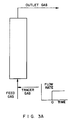
- the Peclet number of a given reactor can be determined from a tracer test for that reactor or a geometrically equivalent non-reactive mockup unit at milder but well defined conditions. Inert gas is fed to the bottom of the reactor and after allowing the system to equilibrate a small concentration of a tracer gas is added to the feed stream as a step function (cf. Figure 3A). Then by measuring the shape of the concentration profile of the tracer in the gas outlet stream, the Peclet number can be determined for the reactor by matching experimental results to model calculations.
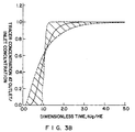
- t is the time measured from the tracer injection multiplied by U g H/E with E being the gas holdup in the column.
- the Peclet number is the only parameter in this equation. For infinitely large Peclet numbers (i.e., plug-flow), the output is a delayed step function; and as the Pe number is decreased (backmixing increases), the output response is more spread out in time. If the response pulse falls outside of the shaded area in Figure 3B, the Peclet number is less than 1, and the reactor begins to give decreased conversion because of backmixing.
- Example 4 Catalyst Distribution as a Function of Gas Velocity
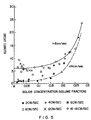
- the solids distributions of glass beads and of titania particles in HCS wax were determined in a 15.2 cm (6") diameter non-reactive bubble column by taking samples from the vessel at 1 meter intervals.
- the temperature was 204°C (400°F) and the gauge pressure was 1929 kPa (280 psig) for gas velocities below 8 cm/sec and 1034 kPa (150 psig) for gas velocities above 8 cm/sec.
- the decay length was obtained by taking the slope of a line segment joining the data points when plotted as the logarithm of the solids concentration versus height. In Figure 5, the decay length in each zone is plotted versus the average concentration in the zone for superficial gas velocities of 2-16 cm/sec.
- Example 6 Method for Predicting Solids Distribution in a Slurry Bubble Column Reactor
- Example 5 allow one to predict the catalyst distribution in a slurry bubble column reactor via the following algorithm.
- the reactor is charged with n species of particles each of which has a Stokes settling velocity U i and average concentration C io .
- a given species may or may not be catalytic.
- the algorithm begins by guessing the values of all the C i 's at the bottom of the reactor and then the equations for the C i 's are integrated numerically until the top of the slurry is reached.
- the gas velocity is computed by requiring a given overall conversion, J, and assuming the extent of reaction at any height is proportional to the fraction of the total catalyst inventory below that height; thus where U go is the gas velocity at the inlet and the sum is over the reactive solid species only.
- the total predicted inventory for each solid species is compared to the known charge; i.e., we check that where E is the volume fraction of gas (i.e., the gas holdup) at height x and H is the height of the slurry.
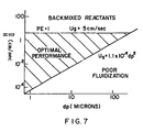
- the reactor geometry and operating conditions must be chosen such that they lie within the shaded triangle shown in Figure 6.
Landscapes
- Chemical & Material Sciences (AREA)
- Engineering & Computer Science (AREA)
- Organic Chemistry (AREA)
- Chemical Kinetics & Catalysis (AREA)
- Oil, Petroleum & Natural Gas (AREA)
- Combustion & Propulsion (AREA)
- General Chemical & Material Sciences (AREA)
- Devices And Processes Conducted In The Presence Of Fluids And Solid Particles (AREA)
- Organic Low-Molecular-Weight Compounds And Preparation Thereof (AREA)
- Physical Or Chemical Processes And Apparatus (AREA)
- Treating Waste Gases (AREA)
Claims (8)
- Verfahren zum optimalen Betreiben einer Dreiphasen-Suspensionsblasensäule für die Herstellung von Fischer-Tropsch-Kohlenwasserstoffsyntheseparaffin, in der Katalysatorfeststoffteilchen in der flüssigen Phase durch Bläschen der Gasphase aufgewirbelt werden, bei demwobeia) die Gasphase mit einer durchschnittlichen Gasgeschwindigkeit entlang der Säule, Ug, in die Säule mit einem Durchmesser von mindestens 15 cm injiziert wird, sodass die herrschende Strömung in wesentlicher Abwesenheit von Brecherströmung ist,b) auf anorganischem Oxid geträgerte Kobaltkatalysatorteilchen mit einem mittleren Durchmesser dp > 30 µm in der flüssigen Phase auf eine Höhe H von mehr als 3 Meter in der Säule aufgewirbelt werden, indem die Säule mit einer Feststoffteilchenabsetzgeschwindigkeit Us und einem Dispersionskoeffizienten D betrieben wird, sodass:c) in der Säule Propfenströmung aufrechterhalten wird, indem sie mit einer Gasphasengeschwindigkeit Ug, expandierter Flüssigkeitshöhe H und Dispersionskoeffizient D betrieben wird, sodassd) Kohlenwasserstoffsyntheseparaffin als Flüssigkeit verwendet wird,
- ρs =
- effektive Dichte der Teilchen
- ρl =
- Dichte der Flüssigkeit
- µ =
- Viskosität der Flüssigkeit
- f(Cp) =
- gehinderte Absetzfunktion
- Cp =
- Volumenfraktion der Feststoffe in der Suspension (Flüssigkeit plus Feststoffe)
- UL =
- Flüssigkeitsgeschwindigkeit entlang der Säule
- H =
- Höhe der expandierten Flüssigkeit in dem Reaktor
- G =
- Gravitationskonstante
- dp =
- Durchmesser der Katalysatorteilchen.
- Verfahren nach Anspruch 1, bei dem
- Verfahren nach Anspruch 1 oder 2, bei dem der Katalysator zusätzliche Promoter ausgewählt aus Metallen der Gruppe I, Gruppe II, Gruppe V und Gruppe VII einschließt.
- Verfahren nach einem der vorhergehenden Ansprüche, bei dem die Gasgeschwindigkeit
- Verfahren nach einem der vorhergehenden Ansprüche, bei dem UL ≤ 1/2 US, z.B. UL ≤ 0,5 cm/s ist.
- Verfahren nach einem der vorhergehenden Ansprüche, bei dem UL in Abwesenheit von Flüssigkeitsrückführung bestimmt wird.
- Verfahren nach einem der vorhergehenden Ansprüche, bei dem die durchschnittliche Gasgeschwindigkeit Ug bis zu 25 cm/s beträgt.
- Verfahren nach einem der vorhergehenden Ansprüche, bei dem der Reaktor ein Suspensionsblasensäulenreaktor im gewerblichen Maßstab ist.
Applications Claiming Priority (2)
| Application Number | Priority Date | Filing Date | Title |
|---|---|---|---|
| US50474690A | 1990-04-04 | 1990-04-04 | |
| US504746 | 1990-04-04 |
Publications (4)
| Publication Number | Publication Date |
|---|---|
| EP0450860A2 EP0450860A2 (de) | 1991-10-09 |
| EP0450860A3 EP0450860A3 (en) | 1992-03-18 |
| EP0450860B1 EP0450860B1 (de) | 1994-10-05 |
| EP0450860B2 true EP0450860B2 (de) | 2005-04-20 |
Family
ID=24007560
Family Applications (1)
| Application Number | Title | Priority Date | Filing Date |
|---|---|---|---|
| EP91302710A Expired - Lifetime EP0450860B2 (de) | 1990-04-04 | 1991-03-27 | Methode zum Betrieb einer Gas-Flüssig-Blasenkolonne in Suspension |
Country Status (7)
| Country | Link |
|---|---|
| US (1) | USRE39073E1 (de) |
| EP (1) | EP0450860B2 (de) |
| AU (1) | AU632413B2 (de) |
| CA (1) | CA2038774C (de) |
| DE (1) | DE69104400T3 (de) |
| MY (1) | MY107587A (de) |
| NO (1) | NO180001C (de) |
Families Citing this family (40)
| Publication number | Priority date | Publication date | Assignee | Title |
|---|---|---|---|---|
| GB9203959D0 (en) * | 1992-02-25 | 1992-04-08 | Norske Stats Oljeselskap | Method of conducting catalytic converter multi-phase reaction |
| GB9203958D0 (en) * | 1992-02-25 | 1992-04-08 | Norske Stats Oljeselskap | Catalytic multi-phase reactor |
| US5599849A (en) * | 1993-01-27 | 1997-02-04 | Sasol Chemical Industries (Proprietary) Limited | Process for producing liquid and, optionally, gaseous products from gaseous reactants |
| GB9301723D0 (en) * | 1993-01-28 | 1993-03-17 | Norske Stats Oljeselskap | Solid/liquid treatment apparatus and catalytic multi-phase reactor |
| US6069179A (en) * | 1993-02-24 | 2000-05-30 | Den Norske Stats Oljeselskap As | Method of conducting catalytic converter multi-phase reaction |
| GB2281224B (en) * | 1993-08-24 | 1998-02-11 | Norske Stats Oljeselskap | Solid/liquid slurry treatment apparatus and catalytic multi-phase reactor |
| IT1283774B1 (it) * | 1996-08-07 | 1998-04-30 | Agip Petroli | Processo di fischer-tropsch con reattore a colonna a bolle multistadio |
| EP0824961A1 (de) | 1996-08-23 | 1998-02-25 | Shell Internationale Researchmaatschappij B.V. | Gasverteiler für einen Suspensionsreaktor und dessen Gebrauch |
| AU720266B2 (en) * | 1996-12-16 | 2000-05-25 | Res Usa, Llc | Catalyst/wax separation device for slurry fischer-tropsch reactor |
| IT1312356B1 (it) | 1999-06-17 | 2002-04-15 | Eni Spa | Procedimento migliorato di fischer-tropsch |
| FR2806642B1 (fr) | 2000-03-27 | 2002-08-23 | Inst Francais Du Petrole | Procede de conversion d'hydrocarbures dans un reacteur triphasique |
| US6776898B1 (en) † | 2000-04-04 | 2004-08-17 | Exxonmobil Research And Engineering Company | Process for softening fischer-tropsch wax with mild hydrotreating |
| GB2410449B (en) * | 2004-01-28 | 2008-05-21 | Statoil Asa | Fischer-Tropsch catalysts |
| US7183327B2 (en) * | 2004-03-18 | 2007-02-27 | Conocophillips Company | Optimized particle distribution for slurry bubble column reactors |
| AU2005240425B2 (en) | 2004-05-10 | 2010-12-02 | Sasol Technology (Proprietary) Limited | The production of liquid and, optionally, gaseous hydrocarbons from gaseous reactants into an expanded slurry bed |
| WO2007069317A1 (ja) | 2005-12-14 | 2007-06-21 | Nippon Steel Engineering Co., Ltd. | 気泡塔型フィッシャー・トロプシュ合成スラリー床反応システム |
| DE102006015541A1 (de) * | 2006-03-31 | 2007-10-04 | List Holding Ag | Verfahren und Vorrichtung zur Behandlung von zähviskosen Produkten |
| EP1852182A1 (de) * | 2006-05-01 | 2007-11-07 | Engelhard Corporation | Fischer-Tropsch-Katalysator enthaltend Kobalt und Zinkoxid |
| US7271201B1 (en) | 2006-08-07 | 2007-09-18 | Syntroleum Corporation | Use of waste heat from Fischer-Tropsch synthesis to form dry pulverized fuel feedstock |
| FR2910488B1 (fr) | 2006-12-20 | 2010-06-04 | Inst Francais Du Petrole | Procede de conversion de biomasse pour la production de gaz de synthese. |
| GB2446127A (en) * | 2007-01-30 | 2008-08-06 | Gtl F1 Ag | Preparation of Fischer-Tropsch Catalysts |
| US20090005275A1 (en) * | 2007-06-28 | 2009-01-01 | Chevron U.S.A. Inc. | Power steering fluid |
| US7956018B2 (en) | 2007-12-10 | 2011-06-07 | Chevron U.S.A. Inc. | Lubricant composition |
| GB2473071B (en) | 2009-09-01 | 2013-09-11 | Gtl F1 Ag | Fischer-tropsch catalysts |
| US8349776B2 (en) * | 2009-09-29 | 2013-01-08 | Chevron Oronite Company Llc | Trunk piston engine lubricating oil compositions |
| GB2475492B (en) | 2009-11-18 | 2014-12-31 | Gtl F1 Ag | Fischer-Tropsch synthesis |
| CN103249481B (zh) | 2010-08-09 | 2015-11-25 | Gtl.F1公司 | 费托催化剂 |
| US20120144887A1 (en) | 2010-12-13 | 2012-06-14 | Accelergy Corporation | Integrated Coal To Liquids Process And System With Co2 Mitigation Using Algal Biomass |
| US8702968B2 (en) | 2011-04-05 | 2014-04-22 | Chevron Oronite Technology B.V. | Low viscosity marine cylinder lubricating oil compositions |
| AP2013007261A0 (en) | 2011-06-07 | 2013-11-30 | Sasol Tech Pty Ltd | Process for producing at least one product from atleast one gaseous reactant in a slurry bed |
| CN103596674B (zh) | 2011-06-07 | 2015-12-02 | 沙索技术有限公司 | 用于在浆态床中由至少一种气态反应物产生至少一种产物的方法 |
| US9234139B2 (en) | 2011-11-01 | 2016-01-12 | Accelergy Corporation | Diesel fuel production process employing direct and indirect coal liquefaction |
| US9206374B2 (en) | 2011-12-16 | 2015-12-08 | Chevron Oronite Sas | Trunk piston engine lubricating oil compositions |
| RU2674144C2 (ru) * | 2013-08-26 | 2018-12-05 | Шелл Интернэшнл Рисерч Маатсхаппий Б.В. | Способ получения гликолей |
| CN105829513B (zh) | 2013-11-06 | 2020-09-15 | 雪佛龙奥伦耐技术有限责任公司 | 船用柴油机汽缸润滑剂油组合物 |
| SG11201603377YA (en) | 2013-11-06 | 2016-05-30 | Chevron Oronite Technology Bv | Marine diesel cylinder lubricant oil compositions |
| US9358526B2 (en) | 2013-11-19 | 2016-06-07 | Emerging Fuels Technology, Inc. | Optimized fischer-tropsch catalyst |
| US9180436B1 (en) | 2013-11-19 | 2015-11-10 | Emerging Fuels Technology, Inc. | Optimized fischer-tropsch catalyst |
| KR102403745B1 (ko) | 2015-07-22 | 2022-05-31 | 셰브런 오로나이트 테크놀로지 비.브이. | 선박 디젤 실린더 윤활유 조성물 |
| WO2025217019A1 (en) * | 2024-04-09 | 2025-10-16 | Chevron Phillips Chemical Company Lp | End-use applications for low viscosity and high flash point pao solvents |
Family Cites Families (16)
| Publication number | Priority date | Publication date | Assignee | Title |
|---|---|---|---|---|
| DE914374C (de) | 1943-09-16 | 1954-07-01 | Rheinpreussen Ag | Verfahren zur Umwandlung von gesaettigten Ketten- und Ringkohlenwasserstoffen in hoehermolekulare Paraffin- bis wachsartige Kohlen-wasserstoffe oder deren Sauerstoffverbindungen |
| US2671103A (en) * | 1949-10-28 | 1954-03-02 | Rheinpreussen Ag | Catalytic hydrogenation of carbon monoxide in liquid suspensions of catalyst |
| DE977498C (de) | 1949-10-29 | 1966-11-03 | Phil Herbert Koelbel Dr | Verfahren zur Kohlenoxydhydrierung |
| GB709645A (en) | 1951-06-30 | 1954-06-02 | Rheinpreussen Ag | A process for the conversion of carbon dioxide with hydrogen |
| US3644192A (en) * | 1970-08-28 | 1972-02-22 | Sik U Li | Upflow three-phase fluidized bed coal liquefaction reactor system |
| US4261899A (en) * | 1980-04-28 | 1981-04-14 | Chem Systems Inc. | Phthalic anhydride reaction system |
| US4396539A (en) | 1981-08-14 | 1983-08-02 | Sapienza Richard S | Hydrocarbon synthesis catalyst and method of preparation |
| US4595703A (en) | 1984-06-29 | 1986-06-17 | Exxon Research And Engineering Co. | Preparation of hydrocarbons from synthesis gas |
| AU592057B2 (en) | 1984-07-30 | 1990-01-04 | Shell Internationale Research Maatschappij B.V. | Converions of synthesis gas to diesel fuel in controlled particle size fluid system |
| US4670472A (en) | 1985-06-05 | 1987-06-02 | Air Products And Chemicals, Inc. | Fischer-Tropsch process |
| US4619910A (en) | 1985-06-05 | 1986-10-28 | Air Products And Chemicals, Inc. | Catalyst for selective conversion of synthesis gas and method of making the catalyst |
| US4801573A (en) * | 1987-10-23 | 1989-01-31 | 501 Den Norske Stats Oljeslenskap A.S. | Catalyst for production of hydrocarbons |
| US4857559A (en) * | 1987-10-23 | 1989-08-15 | Gas-To-Oil, Inc. | Process for production of hydrocarbons |
| CA2038773C (en) | 1990-04-04 | 1999-06-08 | Kym B. Arcuri | Slurry fischer-tropsch process with co/ti02 catalyst |
| CA2038772C (en) | 1990-04-04 | 2001-12-25 | Eric Herbolzheimer | Catalyst fluidization improvements |
| ZA985992B (en) | 1997-07-15 | 2000-01-10 | Sasol Tech Pty Ltd | A process for producing liquid and, optionally, gaseous products from gaseous reactants. |
-
1991
- 1991-03-21 CA CA002038774A patent/CA2038774C/en not_active Expired - Lifetime
- 1991-03-25 NO NO19911209A patent/NO180001C/no not_active IP Right Cessation
- 1991-03-27 DE DE69104400T patent/DE69104400T3/de not_active Expired - Lifetime
- 1991-03-27 EP EP91302710A patent/EP0450860B2/de not_active Expired - Lifetime
- 1991-03-29 MY MYPI91000526A patent/MY107587A/en unknown
- 1991-04-03 AU AU74015/91A patent/AU632413B2/en not_active Expired
-
2004
- 2004-09-29 US US10/953,621 patent/USRE39073E1/en not_active Expired - Lifetime
Also Published As
| Publication number | Publication date |
|---|---|
| DE69104400T2 (de) | 1995-05-04 |
| USRE39073E1 (en) | 2006-04-18 |
| NO911209D0 (no) | 1991-03-25 |
| DE69104400T3 (de) | 2005-10-27 |
| NO180001B (no) | 1996-10-21 |
| CA2038774A1 (en) | 1991-10-05 |
| CA2038774C (en) | 2001-09-25 |
| DE69104400D1 (de) | 1994-11-10 |
| AU7401591A (en) | 1991-10-10 |
| EP0450860A2 (de) | 1991-10-09 |
| MY107587A (en) | 1996-04-30 |
| AU632413B2 (en) | 1992-12-24 |
| NO180001C (no) | 2008-04-07 |
| EP0450860A3 (en) | 1992-03-18 |
| EP0450860B1 (de) | 1994-10-05 |
| NO911209L (no) | 1991-10-07 |
Similar Documents
| Publication | Publication Date | Title |
|---|---|---|
| EP0450860B2 (de) | Methode zum Betrieb einer Gas-Flüssig-Blasenkolonne in Suspension | |
| US5348982A (en) | Slurry bubble column (C-2391) | |
| US5157054A (en) | Catalyst fluidization improvements (C-2546) | |
| Maretto et al. | Modelling of a bubble column slurry reactor for Fischer–Tropsch synthesis | |
| CA2210691C (en) | Fischer-tropsch process with a multistage bubble column reactor | |
| EP0450861B1 (de) | Verfahren zur Kohlenwasserstoffsynthese durch Fischer-Tropsch Schlammverfahren mit Co/TiO2 Katalysator | |
| AU2004223835A1 (en) | Commercial Fischer-Tropsch reactor | |
| EP1129776B2 (de) | Kobalthaltiger Trägerkatalysator | |
| WO2002059232A2 (en) | Process for operating a fischer-tropsch reactor | |
| De Swart et al. | Selection, design and scale up of the Fischer-Tropsch reactor | |
| RU2195476C2 (ru) | Усовершенствованный способ фишера-тропша | |
| CA2038772C (en) | Catalyst fluidization improvements | |
| US20030114543A1 (en) | Slurry bed reactor | |
| EP0363802A2 (de) | Hochvolumetrische Herstellung von Methanol in einem Flüssigkeitsphasenreaktor | |
| Jacobs et al. | Reactor approaches for Fischer–Tropsch synthesis | |
| JP2004532339A (ja) | フィッシャー−トロプシュ法 | |
| US20040235967A1 (en) | Recycle of low boiling point products to a fischer-tropsch reactor | |
| US7183327B2 (en) | Optimized particle distribution for slurry bubble column reactors | |
| Kang et al. | Hydrogenation of CO on supported cobalt γ-Al2O3 catalyst in fixed bed and slurry bubble column reactors | |
| WO2018078069A1 (en) | A fischer-tropsch catalyst body | |
| Saha et al. | Mathematical model for commercial scale slurry bubble column reactor for Fischer-Tropsch synthesis |
Legal Events
| Date | Code | Title | Description |
|---|---|---|---|
| PUAI | Public reference made under article 153(3) epc to a published international application that has entered the european phase |
Free format text: ORIGINAL CODE: 0009012 |
|
| AK | Designated contracting states |
Kind code of ref document: A2 Designated state(s): DE FR GB IT NL |
|
| PUAL | Search report despatched |
Free format text: ORIGINAL CODE: 0009013 |
|
| AK | Designated contracting states |
Kind code of ref document: A3 Designated state(s): DE FR GB IT NL |
|
| 17P | Request for examination filed |
Effective date: 19920810 |
|
| 17Q | First examination report despatched |
Effective date: 19921112 |
|
| GRAA | (expected) grant |
Free format text: ORIGINAL CODE: 0009210 |
|
| AK | Designated contracting states |
Kind code of ref document: B1 Designated state(s): DE FR GB IT NL |
|
| REF | Corresponds to: |
Ref document number: 69104400 Country of ref document: DE Date of ref document: 19941110 |
|
| ET | Fr: translation filed | ||
| ITF | It: translation for a ep patent filed | ||
| PLBI | Opposition filed |
Free format text: ORIGINAL CODE: 0009260 |
|
| 26 | Opposition filed |
Opponent name: SHELL INTERNATIONALE RESEARCH MAATSCHAPPIJ B.V. Effective date: 19950705 |
|
| NLR1 | Nl: opposition has been filed with the epo |
Opponent name: SHELL INTERNATIONALE RESEARCH MAATSCHAPPIJ B.V. IN |
|
| PLBF | Reply of patent proprietor to notice(s) of opposition |
Free format text: ORIGINAL CODE: EPIDOS OBSO |
|
| PLBF | Reply of patent proprietor to notice(s) of opposition |
Free format text: ORIGINAL CODE: EPIDOS OBSO |
|
| TPAD | Observations filed by third parties |
Free format text: ORIGINAL CODE: EPIDOS TIPA |
|
| PLAW | Interlocutory decision in opposition |
Free format text: ORIGINAL CODE: EPIDOS IDOP |
|
| APAC | Appeal dossier modified |
Free format text: ORIGINAL CODE: EPIDOS NOAPO |
|
| APAE | Appeal reference modified |
Free format text: ORIGINAL CODE: EPIDOS REFNO |
|
| APAC | Appeal dossier modified |
Free format text: ORIGINAL CODE: EPIDOS NOAPO |
|
| RAP2 | Party data changed (patent owner data changed or rights of a patent transferred) |
Owner name: EXXONMOBIL RESEARCH AND ENGINEERING COMPANY |
|
| NLT2 | Nl: modifications (of names), taken from the european patent patent bulletin |
Owner name: EXXONMOBIL RESEARCH AND ENGINEERING COMPANY |
|
| REG | Reference to a national code |
Ref country code: GB Ref legal event code: IF02 |
|
| APAC | Appeal dossier modified |
Free format text: ORIGINAL CODE: EPIDOS NOAPO |
|
| PLAY | Examination report in opposition despatched + time limit |
Free format text: ORIGINAL CODE: EPIDOSNORE2 |
|
| PLBC | Reply to examination report in opposition received |
Free format text: ORIGINAL CODE: EPIDOSNORE3 |
|
| PLAY | Examination report in opposition despatched + time limit |
Free format text: ORIGINAL CODE: EPIDOSNORE2 |
|
| PLBC | Reply to examination report in opposition received |
Free format text: ORIGINAL CODE: EPIDOSNORE3 |
|
| PUAH | Patent maintained in amended form |
Free format text: ORIGINAL CODE: 0009272 |
|
| STAA | Information on the status of an ep patent application or granted ep patent |
Free format text: STATUS: PATENT MAINTAINED AS AMENDED |
|
| 27A | Patent maintained in amended form |
Effective date: 20050420 |
|
| AK | Designated contracting states |
Kind code of ref document: B2 Designated state(s): DE FR GB IT NL |
|
| NLR2 | Nl: decision of opposition |
Effective date: 20050420 |
|
| NLR3 | Nl: receipt of modified translations in the netherlands language after an opposition procedure | ||
| APAH | Appeal reference modified |
Free format text: ORIGINAL CODE: EPIDOSCREFNO |
|
| ET3 | Fr: translation filed ** decision concerning opposition | ||
| PGFP | Annual fee paid to national office [announced via postgrant information from national office to epo] |
Ref country code: IT Payment date: 20100317 Year of fee payment: 20 Ref country code: FR Payment date: 20100318 Year of fee payment: 20 |
|
| PGFP | Annual fee paid to national office [announced via postgrant information from national office to epo] |
Ref country code: GB Payment date: 20100208 Year of fee payment: 20 |
|
| PGFP | Annual fee paid to national office [announced via postgrant information from national office to epo] |
Ref country code: NL Payment date: 20100308 Year of fee payment: 20 Ref country code: DE Payment date: 20100331 Year of fee payment: 20 |
|
| REG | Reference to a national code |
Ref country code: DE Ref legal event code: R071 Ref document number: 69104400 Country of ref document: DE |
|
| REG | Reference to a national code |
Ref country code: NL Ref legal event code: V4 Effective date: 20110327 |
|
| REG | Reference to a national code |
Ref country code: GB Ref legal event code: PE20 Expiry date: 20110326 |
|
| PG25 | Lapsed in a contracting state [announced via postgrant information from national office to epo] |
Ref country code: NL Free format text: LAPSE BECAUSE OF EXPIRATION OF PROTECTION Effective date: 20110327 |
|
| PG25 | Lapsed in a contracting state [announced via postgrant information from national office to epo] |
Ref country code: GB Free format text: LAPSE BECAUSE OF EXPIRATION OF PROTECTION Effective date: 20110326 |
|
| PG25 | Lapsed in a contracting state [announced via postgrant information from national office to epo] |
Ref country code: DE Free format text: LAPSE BECAUSE OF EXPIRATION OF PROTECTION Effective date: 20110327 |