EP0450146B1 - Filling and sealing apparatus - Google Patents
Filling and sealing apparatus Download PDFInfo
- Publication number
- EP0450146B1 EP0450146B1 EP90118551A EP90118551A EP0450146B1 EP 0450146 B1 EP0450146 B1 EP 0450146B1 EP 90118551 A EP90118551 A EP 90118551A EP 90118551 A EP90118551 A EP 90118551A EP 0450146 B1 EP0450146 B1 EP 0450146B1
- Authority
- EP
- European Patent Office
- Prior art keywords
- package
- spout
- recess
- filling
- fusing
- Prior art date
- Legal status (The legal status is an assumption and is not a legal conclusion. Google has not performed a legal analysis and makes no representation as to the accuracy of the status listed.)
- Expired - Lifetime
Links
- 238000007789 sealing Methods 0.000 title claims description 40
- 239000012530 fluid Substances 0.000 claims description 18
- 238000003825 pressing Methods 0.000 claims description 16
- 230000002123 temporal effect Effects 0.000 claims description 9
- 239000002826 coolant Substances 0.000 claims description 5
- 238000007664 blowing Methods 0.000 claims 1
- 230000002093 peripheral effect Effects 0.000 claims 1
- 238000004140 cleaning Methods 0.000 description 23
- 239000007788 liquid Substances 0.000 description 11
- 238000007493 shaping process Methods 0.000 description 10
- 238000004806 packaging method and process Methods 0.000 description 8
- XLYOFNOQVPJJNP-UHFFFAOYSA-N water Substances O XLYOFNOQVPJJNP-UHFFFAOYSA-N 0.000 description 8
- 230000002159 abnormal effect Effects 0.000 description 4
- 230000033228 biological regulation Effects 0.000 description 4
- 230000020169 heat generation Effects 0.000 description 4
- 229920000297 Rayon Polymers 0.000 description 3
- 239000000428 dust Substances 0.000 description 3
- 230000004927 fusion Effects 0.000 description 3
- 238000010438 heat treatment Methods 0.000 description 3
- 239000000463 material Substances 0.000 description 3
- 238000000034 method Methods 0.000 description 3
- 230000001105 regulatory effect Effects 0.000 description 3
- 239000004698 Polyethylene Substances 0.000 description 2
- 230000015572 biosynthetic process Effects 0.000 description 2
- 230000008859 change Effects 0.000 description 2
- 238000010276 construction Methods 0.000 description 2
- 238000001816 cooling Methods 0.000 description 2
- 235000015203 fruit juice Nutrition 0.000 description 2
- 238000003475 lamination Methods 0.000 description 2
- 230000004048 modification Effects 0.000 description 2
- 238000012986 modification Methods 0.000 description 2
- 230000010355 oscillation Effects 0.000 description 2
- -1 polyethylene Polymers 0.000 description 2
- 229920000573 polyethylene Polymers 0.000 description 2
- 230000008569 process Effects 0.000 description 2
- 229920003002 synthetic resin Polymers 0.000 description 2
- 239000000057 synthetic resin Substances 0.000 description 2
- 238000011144 upstream manufacturing Methods 0.000 description 2
- 230000009471 action Effects 0.000 description 1
- 238000005452 bending Methods 0.000 description 1
- 230000000994 depressogenic effect Effects 0.000 description 1
- 238000007599 discharging Methods 0.000 description 1
- 230000003631 expected effect Effects 0.000 description 1
- 238000003780 insertion Methods 0.000 description 1
- 230000037431 insertion Effects 0.000 description 1
- 238000010030 laminating Methods 0.000 description 1
- 238000012858 packaging process Methods 0.000 description 1
- 239000002245 particle Substances 0.000 description 1
- 239000002985 plastic film Substances 0.000 description 1
- 230000002265 prevention Effects 0.000 description 1
- 238000011084 recovery Methods 0.000 description 1
- 229920005989 resin Polymers 0.000 description 1
- 239000011347 resin Substances 0.000 description 1
- 229910001220 stainless steel Inorganic materials 0.000 description 1
- 239000010935 stainless steel Substances 0.000 description 1
- 239000002699 waste material Substances 0.000 description 1
Images


Classifications
-
- B—PERFORMING OPERATIONS; TRANSPORTING
- B29—WORKING OF PLASTICS; WORKING OF SUBSTANCES IN A PLASTIC STATE IN GENERAL
- B29C—SHAPING OR JOINING OF PLASTICS; SHAPING OF MATERIAL IN A PLASTIC STATE, NOT OTHERWISE PROVIDED FOR; AFTER-TREATMENT OF THE SHAPED PRODUCTS, e.g. REPAIRING
- B29C65/00—Joining or sealing of preformed parts, e.g. welding of plastics materials; Apparatus therefor
- B29C65/02—Joining or sealing of preformed parts, e.g. welding of plastics materials; Apparatus therefor by heating, with or without pressure
- B29C65/08—Joining or sealing of preformed parts, e.g. welding of plastics materials; Apparatus therefor by heating, with or without pressure using ultrasonic vibrations
-
- B—PERFORMING OPERATIONS; TRANSPORTING
- B29—WORKING OF PLASTICS; WORKING OF SUBSTANCES IN A PLASTIC STATE IN GENERAL
- B29C—SHAPING OR JOINING OF PLASTICS; SHAPING OF MATERIAL IN A PLASTIC STATE, NOT OTHERWISE PROVIDED FOR; AFTER-TREATMENT OF THE SHAPED PRODUCTS, e.g. REPAIRING
- B29C66/00—General aspects of processes or apparatus for joining preformed parts
- B29C66/01—General aspects dealing with the joint area or with the area to be joined
- B29C66/05—Particular design of joint configurations
- B29C66/10—Particular design of joint configurations particular design of the joint cross-sections
- B29C66/12—Joint cross-sections combining only two joint-segments; Tongue and groove joints; Tenon and mortise joints; Stepped joint cross-sections
- B29C66/122—Joint cross-sections combining only two joint-segments, i.e. one of the parts to be joined comprising only two joint-segments in the joint cross-section
- B29C66/1222—Joint cross-sections combining only two joint-segments, i.e. one of the parts to be joined comprising only two joint-segments in the joint cross-section comprising at least a lapped joint-segment
-
- B—PERFORMING OPERATIONS; TRANSPORTING
- B29—WORKING OF PLASTICS; WORKING OF SUBSTANCES IN A PLASTIC STATE IN GENERAL
- B29C—SHAPING OR JOINING OF PLASTICS; SHAPING OF MATERIAL IN A PLASTIC STATE, NOT OTHERWISE PROVIDED FOR; AFTER-TREATMENT OF THE SHAPED PRODUCTS, e.g. REPAIRING
- B29C66/00—General aspects of processes or apparatus for joining preformed parts
- B29C66/01—General aspects dealing with the joint area or with the area to be joined
- B29C66/05—Particular design of joint configurations
- B29C66/10—Particular design of joint configurations particular design of the joint cross-sections
- B29C66/12—Joint cross-sections combining only two joint-segments; Tongue and groove joints; Tenon and mortise joints; Stepped joint cross-sections
- B29C66/122—Joint cross-sections combining only two joint-segments, i.e. one of the parts to be joined comprising only two joint-segments in the joint cross-section
- B29C66/1224—Joint cross-sections combining only two joint-segments, i.e. one of the parts to be joined comprising only two joint-segments in the joint cross-section comprising at least a butt joint-segment
-
- B—PERFORMING OPERATIONS; TRANSPORTING
- B29—WORKING OF PLASTICS; WORKING OF SUBSTANCES IN A PLASTIC STATE IN GENERAL
- B29C—SHAPING OR JOINING OF PLASTICS; SHAPING OF MATERIAL IN A PLASTIC STATE, NOT OTHERWISE PROVIDED FOR; AFTER-TREATMENT OF THE SHAPED PRODUCTS, e.g. REPAIRING
- B29C66/00—General aspects of processes or apparatus for joining preformed parts
- B29C66/01—General aspects dealing with the joint area or with the area to be joined
- B29C66/05—Particular design of joint configurations
- B29C66/10—Particular design of joint configurations particular design of the joint cross-sections
- B29C66/13—Single flanged joints; Fin-type joints; Single hem joints; Edge joints; Interpenetrating fingered joints; Other specific particular designs of joint cross-sections not provided for in groups B29C66/11 - B29C66/12
- B29C66/131—Single flanged joints, i.e. one of the parts to be joined being rigid and flanged in the joint area
-
- B—PERFORMING OPERATIONS; TRANSPORTING
- B29—WORKING OF PLASTICS; WORKING OF SUBSTANCES IN A PLASTIC STATE IN GENERAL
- B29C—SHAPING OR JOINING OF PLASTICS; SHAPING OF MATERIAL IN A PLASTIC STATE, NOT OTHERWISE PROVIDED FOR; AFTER-TREATMENT OF THE SHAPED PRODUCTS, e.g. REPAIRING
- B29C66/00—General aspects of processes or apparatus for joining preformed parts
- B29C66/50—General aspects of joining tubular articles; General aspects of joining long products, i.e. bars or profiled elements; General aspects of joining single elements to tubular articles, hollow articles or bars; General aspects of joining several hollow-preforms to form hollow or tubular articles
- B29C66/51—Joining tubular articles, profiled elements or bars; Joining single elements to tubular articles, hollow articles or bars; Joining several hollow-preforms to form hollow or tubular articles
- B29C66/53—Joining single elements to tubular articles, hollow articles or bars
- B29C66/532—Joining single elements to the wall of tubular articles, hollow articles or bars
- B29C66/5324—Joining single elements to the wall of tubular articles, hollow articles or bars said single elements being substantially annular, i.e. of finite length
- B29C66/53245—Joining single elements to the wall of tubular articles, hollow articles or bars said single elements being substantially annular, i.e. of finite length said articles being hollow
- B29C66/53246—Joining single elements to the wall of tubular articles, hollow articles or bars said single elements being substantially annular, i.e. of finite length said articles being hollow said single elements being spouts, e.g. joining spouts to containers
- B29C66/53247—Joining single elements to the wall of tubular articles, hollow articles or bars said single elements being substantially annular, i.e. of finite length said articles being hollow said single elements being spouts, e.g. joining spouts to containers said spouts comprising flanges
-
- B—PERFORMING OPERATIONS; TRANSPORTING
- B29—WORKING OF PLASTICS; WORKING OF SUBSTANCES IN A PLASTIC STATE IN GENERAL
- B29C—SHAPING OR JOINING OF PLASTICS; SHAPING OF MATERIAL IN A PLASTIC STATE, NOT OTHERWISE PROVIDED FOR; AFTER-TREATMENT OF THE SHAPED PRODUCTS, e.g. REPAIRING
- B29C66/00—General aspects of processes or apparatus for joining preformed parts
- B29C66/50—General aspects of joining tubular articles; General aspects of joining long products, i.e. bars or profiled elements; General aspects of joining single elements to tubular articles, hollow articles or bars; General aspects of joining several hollow-preforms to form hollow or tubular articles
- B29C66/61—Joining from or joining on the inside
-
- B—PERFORMING OPERATIONS; TRANSPORTING
- B29—WORKING OF PLASTICS; WORKING OF SUBSTANCES IN A PLASTIC STATE IN GENERAL
- B29C—SHAPING OR JOINING OF PLASTICS; SHAPING OF MATERIAL IN A PLASTIC STATE, NOT OTHERWISE PROVIDED FOR; AFTER-TREATMENT OF THE SHAPED PRODUCTS, e.g. REPAIRING
- B29C66/00—General aspects of processes or apparatus for joining preformed parts
- B29C66/50—General aspects of joining tubular articles; General aspects of joining long products, i.e. bars or profiled elements; General aspects of joining single elements to tubular articles, hollow articles or bars; General aspects of joining several hollow-preforms to form hollow or tubular articles
- B29C66/63—Internally supporting the article during joining
-
- B—PERFORMING OPERATIONS; TRANSPORTING
- B29—WORKING OF PLASTICS; WORKING OF SUBSTANCES IN A PLASTIC STATE IN GENERAL
- B29C—SHAPING OR JOINING OF PLASTICS; SHAPING OF MATERIAL IN A PLASTIC STATE, NOT OTHERWISE PROVIDED FOR; AFTER-TREATMENT OF THE SHAPED PRODUCTS, e.g. REPAIRING
- B29C66/00—General aspects of processes or apparatus for joining preformed parts
- B29C66/70—General aspects of processes or apparatus for joining preformed parts characterised by the composition, physical properties or the structure of the material of the parts to be joined; Joining with non-plastics material
- B29C66/72—General aspects of processes or apparatus for joining preformed parts characterised by the composition, physical properties or the structure of the material of the parts to be joined; Joining with non-plastics material characterised by the structure of the material of the parts to be joined
- B29C66/723—General aspects of processes or apparatus for joining preformed parts characterised by the composition, physical properties or the structure of the material of the parts to be joined; Joining with non-plastics material characterised by the structure of the material of the parts to be joined being multi-layered
- B29C66/7232—General aspects of processes or apparatus for joining preformed parts characterised by the composition, physical properties or the structure of the material of the parts to be joined; Joining with non-plastics material characterised by the structure of the material of the parts to be joined being multi-layered comprising a non-plastics layer
- B29C66/72327—General aspects of processes or apparatus for joining preformed parts characterised by the composition, physical properties or the structure of the material of the parts to be joined; Joining with non-plastics material characterised by the structure of the material of the parts to be joined being multi-layered comprising a non-plastics layer consisting of natural products or their composites, not provided for in B29C66/72321 - B29C66/72324
- B29C66/72328—Paper
-
- B—PERFORMING OPERATIONS; TRANSPORTING
- B29—WORKING OF PLASTICS; WORKING OF SUBSTANCES IN A PLASTIC STATE IN GENERAL
- B29C—SHAPING OR JOINING OF PLASTICS; SHAPING OF MATERIAL IN A PLASTIC STATE, NOT OTHERWISE PROVIDED FOR; AFTER-TREATMENT OF THE SHAPED PRODUCTS, e.g. REPAIRING
- B29C66/00—General aspects of processes or apparatus for joining preformed parts
- B29C66/80—General aspects of machine operations or constructions and parts thereof
- B29C66/81—General aspects of the pressing elements, i.e. the elements applying pressure on the parts to be joined in the area to be joined, e.g. the welding jaws or clamps
- B29C66/814—General aspects of the pressing elements, i.e. the elements applying pressure on the parts to be joined in the area to be joined, e.g. the welding jaws or clamps characterised by the design of the pressing elements, e.g. of the welding jaws or clamps
- B29C66/8141—General aspects of the pressing elements, i.e. the elements applying pressure on the parts to be joined in the area to be joined, e.g. the welding jaws or clamps characterised by the design of the pressing elements, e.g. of the welding jaws or clamps characterised by the surface geometry of the part of the pressing elements, e.g. welding jaws or clamps, coming into contact with the parts to be joined
- B29C66/81431—General aspects of the pressing elements, i.e. the elements applying pressure on the parts to be joined in the area to be joined, e.g. the welding jaws or clamps characterised by the design of the pressing elements, e.g. of the welding jaws or clamps characterised by the surface geometry of the part of the pressing elements, e.g. welding jaws or clamps, coming into contact with the parts to be joined comprising a single cavity, e.g. a groove
-
- B—PERFORMING OPERATIONS; TRANSPORTING
- B29—WORKING OF PLASTICS; WORKING OF SUBSTANCES IN A PLASTIC STATE IN GENERAL
- B29C—SHAPING OR JOINING OF PLASTICS; SHAPING OF MATERIAL IN A PLASTIC STATE, NOT OTHERWISE PROVIDED FOR; AFTER-TREATMENT OF THE SHAPED PRODUCTS, e.g. REPAIRING
- B29C66/00—General aspects of processes or apparatus for joining preformed parts
- B29C66/80—General aspects of machine operations or constructions and parts thereof
- B29C66/81—General aspects of the pressing elements, i.e. the elements applying pressure on the parts to be joined in the area to be joined, e.g. the welding jaws or clamps
- B29C66/814—General aspects of the pressing elements, i.e. the elements applying pressure on the parts to be joined in the area to be joined, e.g. the welding jaws or clamps characterised by the design of the pressing elements, e.g. of the welding jaws or clamps
- B29C66/8145—General aspects of the pressing elements, i.e. the elements applying pressure on the parts to be joined in the area to be joined, e.g. the welding jaws or clamps characterised by the design of the pressing elements, e.g. of the welding jaws or clamps characterised by the constructional aspects of the pressing elements, e.g. of the welding jaws or clamps
- B29C66/81457—General aspects of the pressing elements, i.e. the elements applying pressure on the parts to be joined in the area to be joined, e.g. the welding jaws or clamps characterised by the design of the pressing elements, e.g. of the welding jaws or clamps characterised by the constructional aspects of the pressing elements, e.g. of the welding jaws or clamps comprising a block or layer of deformable material, e.g. sponge, foam, rubber
-
- B—PERFORMING OPERATIONS; TRANSPORTING
- B29—WORKING OF PLASTICS; WORKING OF SUBSTANCES IN A PLASTIC STATE IN GENERAL
- B29C—SHAPING OR JOINING OF PLASTICS; SHAPING OF MATERIAL IN A PLASTIC STATE, NOT OTHERWISE PROVIDED FOR; AFTER-TREATMENT OF THE SHAPED PRODUCTS, e.g. REPAIRING
- B29C66/00—General aspects of processes or apparatus for joining preformed parts
- B29C66/80—General aspects of machine operations or constructions and parts thereof
- B29C66/81—General aspects of the pressing elements, i.e. the elements applying pressure on the parts to be joined in the area to be joined, e.g. the welding jaws or clamps
- B29C66/818—General aspects of the pressing elements, i.e. the elements applying pressure on the parts to be joined in the area to be joined, e.g. the welding jaws or clamps characterised by the cooling constructional aspects, or by the thermal or electrical insulating or conducting constructional aspects of the welding jaws or of the clamps ; comprising means for compensating for the thermal expansion of the welding jaws or of the clamps
- B29C66/8181—General aspects of the pressing elements, i.e. the elements applying pressure on the parts to be joined in the area to be joined, e.g. the welding jaws or clamps characterised by the cooling constructional aspects, or by the thermal or electrical insulating or conducting constructional aspects of the welding jaws or of the clamps ; comprising means for compensating for the thermal expansion of the welding jaws or of the clamps characterised by the cooling constructional aspects
- B29C66/81811—General aspects of the pressing elements, i.e. the elements applying pressure on the parts to be joined in the area to be joined, e.g. the welding jaws or clamps characterised by the cooling constructional aspects, or by the thermal or electrical insulating or conducting constructional aspects of the welding jaws or of the clamps ; comprising means for compensating for the thermal expansion of the welding jaws or of the clamps characterised by the cooling constructional aspects of the welding jaws
- B29C66/81812—General aspects of the pressing elements, i.e. the elements applying pressure on the parts to be joined in the area to be joined, e.g. the welding jaws or clamps characterised by the cooling constructional aspects, or by the thermal or electrical insulating or conducting constructional aspects of the welding jaws or of the clamps ; comprising means for compensating for the thermal expansion of the welding jaws or of the clamps characterised by the cooling constructional aspects of the welding jaws the welding jaws being cooled from the outside, e.g. by blowing a gas or spraying a liquid
-
- B—PERFORMING OPERATIONS; TRANSPORTING
- B29—WORKING OF PLASTICS; WORKING OF SUBSTANCES IN A PLASTIC STATE IN GENERAL
- B29C—SHAPING OR JOINING OF PLASTICS; SHAPING OF MATERIAL IN A PLASTIC STATE, NOT OTHERWISE PROVIDED FOR; AFTER-TREATMENT OF THE SHAPED PRODUCTS, e.g. REPAIRING
- B29C66/00—General aspects of processes or apparatus for joining preformed parts
- B29C66/80—General aspects of machine operations or constructions and parts thereof
- B29C66/83—General aspects of machine operations or constructions and parts thereof characterised by the movement of the joining or pressing tools
- B29C66/832—Reciprocating joining or pressing tools
- B29C66/8322—Joining or pressing tools reciprocating along one axis
-
- B—PERFORMING OPERATIONS; TRANSPORTING
- B65—CONVEYING; PACKING; STORING; HANDLING THIN OR FILAMENTARY MATERIAL
- B65B—MACHINES, APPARATUS OR DEVICES FOR, OR METHODS OF, PACKAGING ARTICLES OR MATERIALS; UNPACKING
- B65B61/00—Auxiliary devices, not otherwise provided for, for operating on sheets, blanks, webs, binding material, containers or packages
- B65B61/18—Auxiliary devices, not otherwise provided for, for operating on sheets, blanks, webs, binding material, containers or packages for making package-opening or unpacking elements
- B65B61/186—Auxiliary devices, not otherwise provided for, for operating on sheets, blanks, webs, binding material, containers or packages for making package-opening or unpacking elements by applying or incorporating rigid fittings, e.g. discharge spouts
-
- B—PERFORMING OPERATIONS; TRANSPORTING
- B29—WORKING OF PLASTICS; WORKING OF SUBSTANCES IN A PLASTIC STATE IN GENERAL
- B29C—SHAPING OR JOINING OF PLASTICS; SHAPING OF MATERIAL IN A PLASTIC STATE, NOT OTHERWISE PROVIDED FOR; AFTER-TREATMENT OF THE SHAPED PRODUCTS, e.g. REPAIRING
- B29C35/00—Heating, cooling or curing, e.g. crosslinking or vulcanising; Apparatus therefor
- B29C35/16—Cooling
- B29C2035/1616—Cooling using liquids
-
- B—PERFORMING OPERATIONS; TRANSPORTING
- B29—WORKING OF PLASTICS; WORKING OF SUBSTANCES IN A PLASTIC STATE IN GENERAL
- B29C—SHAPING OR JOINING OF PLASTICS; SHAPING OF MATERIAL IN A PLASTIC STATE, NOT OTHERWISE PROVIDED FOR; AFTER-TREATMENT OF THE SHAPED PRODUCTS, e.g. REPAIRING
- B29C35/00—Heating, cooling or curing, e.g. crosslinking or vulcanising; Apparatus therefor
- B29C35/16—Cooling
- B29C2035/1658—Cooling using gas
-
- B—PERFORMING OPERATIONS; TRANSPORTING
- B29—WORKING OF PLASTICS; WORKING OF SUBSTANCES IN A PLASTIC STATE IN GENERAL
- B29C—SHAPING OR JOINING OF PLASTICS; SHAPING OF MATERIAL IN A PLASTIC STATE, NOT OTHERWISE PROVIDED FOR; AFTER-TREATMENT OF THE SHAPED PRODUCTS, e.g. REPAIRING
- B29C66/00—General aspects of processes or apparatus for joining preformed parts
- B29C66/70—General aspects of processes or apparatus for joining preformed parts characterised by the composition, physical properties or the structure of the material of the parts to be joined; Joining with non-plastics material
- B29C66/73—General aspects of processes or apparatus for joining preformed parts characterised by the composition, physical properties or the structure of the material of the parts to be joined; Joining with non-plastics material characterised by the intensive physical properties of the material of the parts to be joined, by the optical properties of the material of the parts to be joined, by the extensive physical properties of the parts to be joined, by the state of the material of the parts to be joined or by the material of the parts to be joined being a thermoplastic or a thermoset
- B29C66/739—General aspects of processes or apparatus for joining preformed parts characterised by the composition, physical properties or the structure of the material of the parts to be joined; Joining with non-plastics material characterised by the intensive physical properties of the material of the parts to be joined, by the optical properties of the material of the parts to be joined, by the extensive physical properties of the parts to be joined, by the state of the material of the parts to be joined or by the material of the parts to be joined being a thermoplastic or a thermoset characterised by the material of the parts to be joined being a thermoplastic or a thermoset
- B29C66/7392—General aspects of processes or apparatus for joining preformed parts characterised by the composition, physical properties or the structure of the material of the parts to be joined; Joining with non-plastics material characterised by the intensive physical properties of the material of the parts to be joined, by the optical properties of the material of the parts to be joined, by the extensive physical properties of the parts to be joined, by the state of the material of the parts to be joined or by the material of the parts to be joined being a thermoplastic or a thermoset characterised by the material of the parts to be joined being a thermoplastic or a thermoset characterised by the material of at least one of the parts being a thermoplastic
- B29C66/73921—General aspects of processes or apparatus for joining preformed parts characterised by the composition, physical properties or the structure of the material of the parts to be joined; Joining with non-plastics material characterised by the intensive physical properties of the material of the parts to be joined, by the optical properties of the material of the parts to be joined, by the extensive physical properties of the parts to be joined, by the state of the material of the parts to be joined or by the material of the parts to be joined being a thermoplastic or a thermoset characterised by the material of the parts to be joined being a thermoplastic or a thermoset characterised by the material of at least one of the parts being a thermoplastic characterised by the materials of both parts being thermoplastics
-
- B—PERFORMING OPERATIONS; TRANSPORTING
- B29—WORKING OF PLASTICS; WORKING OF SUBSTANCES IN A PLASTIC STATE IN GENERAL
- B29L—INDEXING SCHEME ASSOCIATED WITH SUBCLASS B29C, RELATING TO PARTICULAR ARTICLES
- B29L2031/00—Other particular articles
- B29L2031/712—Containers; Packaging elements or accessories, Packages
- B29L2031/7162—Boxes, cartons, cases
- B29L2031/7166—Cartons of the fruit juice or milk type, i.e. containers of polygonal cross sections formed by folding blanks into a tubular body with end-closing or contents-supporting elements, e.g. gable type containers
-
- B—PERFORMING OPERATIONS; TRANSPORTING
- B31—MAKING ARTICLES OF PAPER, CARDBOARD OR MATERIAL WORKED IN A MANNER ANALOGOUS TO PAPER; WORKING PAPER, CARDBOARD OR MATERIAL WORKED IN A MANNER ANALOGOUS TO PAPER
- B31B—MAKING CONTAINERS OF PAPER, CARDBOARD OR MATERIAL WORKED IN A MANNER ANALOGOUS TO PAPER
- B31B50/00—Making rigid or semi-rigid containers, e.g. boxes or cartons
- B31B50/74—Auxiliary operations
- B31B50/81—Forming or attaching accessories, e.g. opening devices, closures or tear strings
- B31B50/84—Forming or attaching means for filling or dispensing contents, e.g. valves or spouts
-
- Y—GENERAL TAGGING OF NEW TECHNOLOGICAL DEVELOPMENTS; GENERAL TAGGING OF CROSS-SECTIONAL TECHNOLOGIES SPANNING OVER SEVERAL SECTIONS OF THE IPC; TECHNICAL SUBJECTS COVERED BY FORMER USPC CROSS-REFERENCE ART COLLECTIONS [XRACs] AND DIGESTS
- Y10—TECHNICAL SUBJECTS COVERED BY FORMER USPC
- Y10S—TECHNICAL SUBJECTS COVERED BY FORMER USPC CROSS-REFERENCE ART COLLECTIONS [XRACs] AND DIGESTS
- Y10S53/00—Package making
- Y10S53/02—High frequency electric sealing
Definitions
- the present invention relates to a filling and sealing apparatus as defined in the precharacterizing part of Claim 1 for filling a package having one end open and the other end closed with fluid through the open end and then sealing the latter.
- Such a filling and sealing apparatus usually comprises a spout attaching device, a spout fusing device, a filling device and a sealing device.
- the spout attaching device functions to temporarily attach a spout 2 on a flap of an open end portion A of a package 1 having the other end B closed, as shown in Fig. 18.
- a hole 3 is preliminarily provided for temporal attachment of the spout 2.
- the package 1 is formed from the so-called paper lamination material which is formed by laminating on both surfaces of a paper sheet synthetic resin films of such as, for example, polyethylene.
- the spout 2 is a mold of synthetic resin such as polyethylene and has a pouring portion 4 and a flat flange 5.
- the spout fusing device functions to fuse the spout 2 attached temporarily on the package 1 and adhere it to the latter.
- the filling device functions to fill the package 1 with drink material such as liquor or fruit juice through the open end A thereof.
- the sealing device functions to seal the open end A of the package 1 filled with such liquid.
- the package filled with liquid has become a product, as shown in Fig. 19.
- the package is usually in the form of cylinder having square or rectangular cross section and the open end portion A is defined by an upper flap portion C including a pair of opposing flaps and another pair of opposing flaps which are orthogonal to the first flap pair.
- the flaps of the first opposing flap pair are folded to allow edge portions of the flaps of the other pair to be adhered to each other.
- the spout 2 is secured to one (D) of the flaps thus adhered together. Liquid filling the package 1 is poured through the spout 2.
- U.S. Patent No. 4,788,811 discloses a spout fusing device of ultrasonic type for fusing a temporarily attached spout 2 to a package.
- the ultrasonic fusing device is used to heat a flange 5 of the spout 2 and a portion of the package 1 which is in contact therewith, by applying ultrasonic vibration thereto to thereby fuse them together.
- an anvil 6 is inserted into the package 1 so that the flange portion 5 of the spout 2 is held stably and a vibration hone 7 of the ultrasonic fusing device is abutted externally to the spout 2.
- a vibration hone 7 of the ultrasonic fusing device is abutted externally to the spout 2.
- temperature of the anvil 6 may be increased by repeated fusing operations, causing fusing conditions of the spout 2 to be changed with temperature change of the anvil 6.
- fusing conditions of the spout 2 may be changed with temperature change of the anvil 6.
- the package 1 may be fused to the anvil 6, so that the package 1 can not be pulled out easily from the anvil 6 after the fusing operation or it can be broken if pulled out.
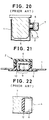
- the hone 7 Since the pouring portion 4 of the spout 2 temporarily attached to the package 1 protrudes outwardly of the package 1, as shown in Fig. 20, the hone 7 has to have a recess 8 for receiving the protruded pouring portion 4 with annular gap therebetween when the hone 7 is positioned to the shown place to apply ultrasonic vibration to the flange 5 of the spout 2. With the annular space provided between the recess 8 and the spout 2, the pouring portion 4 of the latter may be vibrated excessively in direction perpendicular to its axis when ultrasonic vibration is applied through the hone 7 thereto, resulting in pin holes in the spout 2.
- a shield portion 9 provided integrally with the flange 5, as shown in Fig. 21.
- the shield portion 9 functions to prevent the filling liquid in the container 1 from being exposed to atomosphere and is bounded with respect to the flange 5 by an annular thin portion defined by an annular groove 10.
- a pull-up ring 11 is integrally formed on the shield portion 9. That is, when it is desired to pour liquid in the package 1, a cap of the pouring portion 4 is removed from the flange 5 and then the pull-up ring 11 is pulled up by a finger to break the annular groove 10 to thereby separate the shield portion 9 from the flange 5, resulting in an opening.
- an elastic member 12 of such as rubber is provided on a bottom of the recess 8 of the hone 7 so that the pouring portion 4 is urged by the elastic member 12 to absorb excessive vibration, as shown in Fig. 22.
- An object of the present invention is to provide a filling and sealing apparatus in which a spout fusing operation for fusing a spout to a package can be reliably performed for a long period of time.
- the above mentioned filling and sealing apparatus comprises a resilient member as characterized in Claim 1
- the filling and sealing apparatus achieves the above object by preventing vibration of the spout itself during a spout fusing operation by means of the elastic member, preventing abnormal heat generation of the vibration hone even when the elastic member is provided in the vibration hone to thereby preventing application of abnormally large load on an oscillation source for driving the ultrasonic vibration hone at ultrasonic frequency.
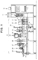
- Fig. 1 shows a filling and sealing apparatus according to the present invention as a whole.
- the filling and sealing apparatus comprises, generally, a packaging portion 13, a package shaping and supplying portion 14 and a operation control portion 15.
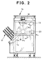
- the package shaping and supplying portion 14 includes eight mandrels 16 arranged radially and equiangularly as shown in Fig. 2.
- Each mandrel 16 takes in the form of cylinder having square or rectangular cross section.
- the mandrels 16 are rotated intermittently in clockwise direction. That is, each mandrel is stopped for a predetermined time at a package proper receiving position P1, a bottom heating position P2, a bottom folding position P3, a bottom sealing position P4 and a package supply position P5, sequentially, in the order.
- a package proper feeder 17 is disposed in the package proper receiving position P1.
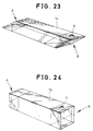
- a plurality of package propers 1a in folded down stock state are stacked as shown in Fig. 23.
- a heater 18 is provided in the bottom heating position P2
- a folding device 19 operable in synchronism with rotation of the mandrels 16 is arranged in the bottom folding position P3 and a bottom press device 20 is arranged in the bottom sealing position P4.
- the packaging portion 13 includes a package conveyer belt 30 extending from the package shaping and supplying portion 14 rightwardly on the drawing sheet.
- the package conveyer belt 30 is reciprocal, intermittently, between a package receiving position P6 (Fig. 3) corresponding to the package supply position P5 (Fig. 2) in the package shaping and supplying portion 14 and a package dischasrge position P7 at which a package product filled with liquid and sealed is discharged.
- a temporal spout attaching device 21 a spout fusing device 22
- a cleaning device 23 a first top breaker device 24, a filling device 25, a second top breaker device 26, a top heater device 27, a package sealing device 28 and a package discharge device 29 are arranged in the sequence.
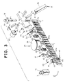
- the filling and sealing apparatus constituted as mentioned above is controlled in operation by a control device (not shown) included in the operation control portion 15. The operation will be described with reference to Fig. 3.
- the stack of the package propers 1a in the folded state (Fig. 23) in the package proper feeder 17 has been described with reference to Fig. 2.
- the lowest one of these package propers 1a in the stack is derived and transported to the package proper receiving position P1.
- the package proper 1a in the folded state (Fig. 23) is shaped to a cylindrical form 1b as shown in Fig. 24, with both end portions A and B of the cylindrical packageproper 1b being kept open.
- the package proper 1b set in the package proper receiving position P1 is fitted on one of the mandrels 16 which is stationary in that position at that time.
- the mandrel 16 on which the package proper 1b is fitted is rotated clockwisely and reaches the bottom heating position P2
- an upper open end of the package proper 1b is heated by the heater 18. Since the package proper 1b is made from a lamination of a paper and plastic sheets sandwitching the paper as mentioned previously, a portion heated by the heater 18 becomes viscose.
- the package proper 1b having the viscose, upper open end is transported to the bottom folding position P3 and, in the position P3, it is temporarily folded inwardly along preliminarily provided foldable lines by the folding device 19.
- the package proper 1b having its end folded temporarily is then transported to the bottom sealing position P4 in which the temporarily folded, viscose upper end thereof is prressed and sealed by the bottom press device 20.
- a package 1 having the end A open and the other end B sealingly closed is obtained as shown in Fig. 18.
- the package 1 formed in this way is then transported to the package supply position P5 in which it is pulled away from the mandrel 16 and is received by the package conveyer belt 30 (Fig. 1) in the package receiving position P6. Thereafter, the package 1 is intermittently transported by the package conveyer belt 30 leftwardly on the drawing sheet (Fig. 1 or 3) and stopped firstly at a position corresponding to the temporal spout attaching device 21.
- the temporal spout attaching device 21 includes a spout dispenser (not shown) containing a number of spouts 2 (Fig. 18) and a spout feeding shute 31 through which the spouts 2 in the spout dispenser is fed one by one to the package transportation path.
- the spout 2 thus supplied is inserted into a hole 3 formed preliminarily in the flap of the upper portion of the package 1 so that it is fitted on an inside of the hole 3 temporarily.
- the package 1 having the spout temporarily fitted thereon is transported to a position facing to the spout fusing device 22 and stopped thereat.
- the spout fusing device 22 includes a ultrasonic fusing device 33 having a ultrasonic vibration hone 7 as shown in Fig. 3.
- the spout 2 temporarily fitted on the package 1 is pushed to the inner surface of the flap of the container 1 by the ultrasonic hone 7 and is subjected, together with the flap, to ultrasonic vibration transmitted by the hone 7. With such ultrasonic vibration, the spout 2 and the inner surface of the flap of the package 1 in contact therewith are heated and melted to form a fused contact therebetween.
- the package 1 having the spout 2 fused thereto is transported to and stopped at a position facing to the cleaning device 23 in which an interior of the package 1 is subjected to a cleaning process. Then, the package 1 is transported to a position facing to the first top breaker device 24.
- the first top breaker device 24 includes a frame 34 and a block 35 connected to the frame 34 and driven in vertical directions by a suitable drive means.
- a pair of folding members 36 is mounted on a lower end of the frame 34.
- the folding members each having triangle shape are swingeable to fold, inwardly, flaps of the upper portion of the package 1 adjacent to the portion thereof on which the spout 2 is fused.
- the folding members 36 are ganged with the block 35 through a suitable link 37.
- the folding members 36 are inwardly swung by an action of the link 37 to temporally fold the flaps of the package 1 along foldable lines (provided on the package preliminarily) to thereby form a roof shape.
- the package 1 is then transported to a position facing to the filling device 25 while the upper portion of the package 1 is gradually recovering from the roof shape by its own elasticity.
- the filling device 25 includes a reservior 38 for storing liquid such as liquor or fruit juice to fill the package 1 and filling nozzles 39a and 39b extending from the resorvior 38.
- the filling nozzles 39a and 39b are adapted to supply the content of the resorvior 38 to a pair of packages 1 simultaneously when these packages come into positions immediately below these nozzles respectively with this simultaneous supply of liquid to two of the packages through the nozzles 39a and 39b, it becomes possible to fill these packages with a predetermined amount of liquid even within short stay in their positions. For example, it may be possible to fill the package 1 completely by filling half through the filling nozzle 39a positioned at an upstream position on the package transportation path and then filling it with the other half by the nozzle 39b positioned in a down stream.
- the package 1 filled with liquid is transported to a position facing to the second top breaker device 26 in which the upper open portion of the package 1 is again folded inwardly along the temporally folded lines by a pair of folding members 41 mounted on a frame 40 thereof. Thereafter, the package 1 is transported up to a position facing to the top heater device 27.
- the top heater device 27 includes a block 42 provided with a pair of heater portions 42a.
- the resin layers of the open end portion of the package 1 are heated thereby to close them together. Then, the package 1 is transported to a position facing to the package sealing device 28.
- the package sealing device 28 includes a pair of blocks 43 for pressing the upper end of the package 1 and a pair of nail members 44 for bending, inwardly, the side surfaces of the upper portion of the package 1 adjacent to the side portion thereof on which the spout 2 is mounted.
- the nail members 44 bend the upper side portions of the package 1 and, simultaneously, the blocks 43 press the upper end portions of the package 1 to firmly adhere them together sealingly.
- the package sealing device 28 further includes an evacuation device 45 for discharging air from the package 1.
- the evacuation device 45 includes a pair of press arms 46 which are arranged on opposite sides of the package transportation path and rotatable in synchronism with the package transportation. The side portions of the upper portion of the package 1 are pressed inwardly by these press arms 46 to rise a liquid level in the package to thereby minimize an air amount therein.
- the package 1 having the upper portion sealed by the package sealing device 28 is transported by the package discharge device 29 (Fig. 1) externally as a product package 1c.
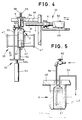
- Fig. 4 is a side view of the spout fusing device 22 in Fig. 1 when looked in rightward direction on the drawing sheet.
- the package 1 is transported vertically on the drawing sheet by the package conveyer belt 30 having nails 47.
- the anvil 6 supported by a frame 48 is fixedly disposed above the package conveyer belt 30.
- the anvil 6 is of, for example, stainless steel and takes a corresponding shape to that of the interior of the package 1.
- the ultrasonic fusing device 33 is provided on the right side f the anvil 6.
- the ultrasonic fusing device 33 includes a converter 50 fixedly secured onto a slide table 49, a booster 51 fixedly secured to the slide table 49 and the vibration hone 7 fixedly secured to a left side of the slide table 49.
- the slide table 49 is recirocally driven in a horizontal directions on the drawing sheet by a drive device which is not shown.
- a package elevator device 52 is arranged beneath the package conveyer belt 30 in a position facing to the anvil 6.
- the package elevator device 52 in constituted with an air cylinder 53, a push-up rod 54 mounted on an actuator rod 53a of the air cylinder 53 and a push-down rod 55 mounted on the same.
- the slide table 49 moved leftwardly on the drawing sheet and a top end (left side end) of the vibration hone 7 contacts with a right side upper surface of the package 1 and presses it to the anvil 6, as shown in Fig. 20.
- the pouring portion 4 (see Fig. 18) of the spout 2 is received in the recess 8 formed in the vibration hone 7.
- the flange 5 of the spout 2 and the inner surface of the package 1 contacting with the latter are heated by ultrasonic vibration, as a result of which the spout flange 5 is fused to the inner wall of the package 1.
- the slide table Upon a completion of the fusing, the slide table is moved rightwardly to detach the hone 7 from the package 1. Then, the air cylinder 53 is actuated to lower the push-down rod 55 to thereby remove the package 1 from the anvil 6. Thereafter, the package 1 is transported by the package conveyer belt 30 to the subsequent stage, that is, the cleaning stage to be performed by the cleaning device 23 (Fig. 1).
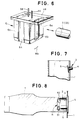
- temperature regulation means for restricting temperature of the anvil 6 is provided in the latter as shown in Fig. 5.
- the temperature regulation means shown in Fig. 5 is constituted with a cavity 57 formed in the anvil 6, a fluid supply pipe 58 extending into a deep portion of the cavity 57 and a fluid discharge pipe 59 extending into a shallow portion of the cavity 57.
- the fluid supply pipe 58 is connected to a fluid supply source which is not shown through a cock 60 so that temperature regulating fluid such as cold water is supplied from the fluid supply source to the anvil cavity 57 through the fluid supply pipe 58.
- the fluid discharge pipe 59 is connected to fluid recovery means (not shown) such as a waste fluid tank to which cold water in the cavity 57 is returned therethrough.
- fluid recovery means such as a waste fluid tank to which cold water in the cavity 57 is returned therethrough.
- the spout fusing device 33 when the spout fusing device 33 is subjected to a very low temperature in such as winter season, there may be a case where the anvil temperature becomes too low and so it is difficult for the ultrasonic fusing device 33 to increase spout temperature to a temperature high enough to fuse the spout 2 to the package 1 which leads to incomplete fusion of the spout 2 to the package 1.
- the temperature regulation means can take any other constructions than that shown in Fig. 5 so long that it can keep the anvil temperature within a constant range.
- a groove 63 having width Wb slightly wider than a width Wa (Fig. 18) of the flange 5 of the spout 2 and extending longitudinally of the direction of insertion of the package is formed in a side surface 6a of the anvil 6 which faces to the vibration hone 7 of the ultrasonic fusing device 33.
- the reason for the formation of such groove as that depicted by 63 in the anvil 6 is as follow.
- An attitude of the spout 2 temporally mounted to the package 1 is not always normal and there may be a case where it is temporarily mounted on the package in a tilted state as shown in Fig. 7. In such case, there may be a case where, when the package 1 is being fitted on the anvil 6, the flange 5 of the spout 2 collides with the side surface 6a of the anvil 6, leading to unsuitable fitting. In order to prevent this, the groove 63 is provided.
- Another groove 64 formed in another side furface 6b of the anvil 6 provides a relief space for the nails 65 fixedly secured to the push-down rod 55 shown in Fig. 4.
- the recess 8 formed in the ultrasonic hone 7 of the ultrasonic fusing device 33 shown in Fig. 4 is constructed as to be described below.
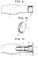
- a resilient member 61 is provided in the recess 8 (see Fig. 9) of the vibration hone 7.
- the resilient member 61 functions to press the spout cap 4 when the spout flange 5 is fused to the inner wall of the package 1 by the top end of the vibration hone 7 to thereby prevent the spout 2 from being vibrated thereby. Formation of any pin hole in the flange portion 5 during the fusing can be prevented by the prevention of vibration of the spout 2.
- the resilient member 61 has a substantial square cross section as shown in Fig. 10 and each of four corner portions 62 is rounded so that it corresponds to an inner surface configuration of the recess 8.
- each of four corner portions 62 is rounded so that it corresponds to an inner surface configuration of the recess 8.
- the resilient member 61 When the resilient member 61 is fitted in the recess 8, it is in contact with the inner surface of the recess 8 at the corner portions 62 and a rear surface R thereof. That is, the resilient member 61 is in contact with the inner surface of the recess 8 not completely with the whole surface thereof but partially with the corner portions 62.
- a structure shown in Fig. 11 may be used instead of the structure shown in Fig. 8.
- a mounting recess 66 having a circular cross section and communicated with the recess is formed in the vibration hone 7 as shown in Fig. 12.
- the elastic member 71 is composed of a spout pressing portion 72 for preventing undesired vibration of the spout by contacting with the cap 4 under a suitable pressure and a support portion 73 formed integrally with the spot pressing portion 72, as shown in Fig. 13.
- the spout pressing portion 72 has corner portions 62 which are partially contact with an inner surface of the recess 8 of the vibration hone 7. as shown in Fig. 14, the spout pressing portion 72 having such corner portions 62 has a sunbstantial square cross section as in the resilient member 61 in Fig. 10 and is adapted to be in contact with the inner surface of the recess 8 with the four corners 62 and a rear surface R. That is, the both are partially in contact with each other.
- the corner portions 62 are rounded concomitantly with the inner surface configulation of the recess 8.
- the support portion 73 is, generally, in the shape of a cylinder having diameter smaller than that of a mounting recess 66 provided in the vibration hone 7.
- the cylinder has an enlarged diameter portion 74 in a middle portion thereof whose diameter is selected such that it partially contacts with an inner surface of the mounting recess 66.
- the top end of the hone 7 is abutted to the spout flange 5 through the package 1 such that a protruded portion of the vibration hone 7, that is, the pouring portion 4 of the spout 2 is surrounded by the top end portion of the hone 7.
- the resilient member 61 (Fig. 8) or the spout pressing portin 72 (Fig. 11) presses the pouring portion 4 with a suitable pressure, so that vibration of the spout 2 is prevented.
- an amount of deformation of the resilient member 61 or the spout pressing portion 72 depends upon the configulation of the inner surface of the hone recess 8, it is preferable to select the amount of deformation in usual case such that it is depressed down by 2 to 3 mm during the spout fusing operation.
- the resilient member 61 (Fig. 8) is partially in contact with the hone recess 8 at the corner portions 62 and the rear periphery R.
- the resilient member 71 (Fig. 11) has the spout pressing portion 72 in contact with the hone recess 8 at the corner portions 62 and the rear periphery R and the support portion 73 in contact with the mounting recess 66 at the enlarged diameter portion 74. That is, either of the resilient member 61 or the spout pressing portion 72 partially contacts with the recess 8 or 66 of the vibration hone 7. Therefore, a contact area between the resilient member 61 or the spout pressing portion 71 with the hone 7 becomes very small, resulting in frictional heat generation minimized.
- the vibration hone 7 is hardly heated excessively even if it is used for a long time and thus an abnormal large load on the converter 50 and the booster 51 (Fig. 4) for actuating the vibration hone 7 is avoided. Consequently, it becomes possible to perform the spout fusing operation reliably for a long time.
- the support portion 73 is hardly broken by pressing force applied thereto during the fusing operation due to the contact of the enlarged portion 74 thereof with the mounting recess 66, thus it is possible to press the spout 2 reliably.
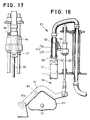
- the cleaning device 23 arranged subsequent to the spout fusing device 22 includes a coaxial cleaning pipe 77 composed of an outer blow pipe 70 having an annular air jet nozzle 69 for jetting air aupplied through an air intake hole 68 and an inner suction pipe 76 having a suction hole 75 for removing foreign materials, as shown in Figs. 16 and 17.
- the blow pipe 70 and the suction pipe 76 are connected to an air pressure source and a vacuum source through suitable control valves, respectively.
- the cleaning device 23 further includes cleaning pipe elevation means 78 for lowering the cleaning pipe 77 down through the upper opening A (Fig. 18) into the package 1 when the package 1 comes up to a position immediately beneath the cleaning device 23.
- the elevation means 78 includes a drive shaft 79 coupled to the drive source of the package conveyer belt 30, a cam 80 rotatably driven by the drive shaft 79, a cam lever 81 swingeable around a support shaft 81a by the cam 80 and a rod 82 vertically driven by the cam lever 81.
- a roller 83 is mounted rotatably on the cam lever 81 and in contact with an outer periphery of the cam 80. The roller 83 is deviated in position with rotation of the cam 80 to swing the cam lever 81 about the support shaft 81a.
- the elevation means 78 is driven by the same drive source as that of the package conveyer belt 30, the overall structure of the filling and sealing apparatus becomes simpler and its control becomes easier compared with the conventional apparatus.
- the cleaning pipe 77 is supported by a bracket 84 fixedly secured to the rod 82 constituting the elevation means 78 and vertically driven by the vertical movement of the rod 82, within a range which can be regulated by changing the position of the bracket 84.
- the air jetting and dust sucking operations may be performed not only during a lowering stroke of the cleaning pipe 77 but also during an elevation stroke thereof. Further, these operations may be performed twice during lowering and elevation strokes.
- the cleaning unit 23 may be arranged in between the first top breaker device 24 and the filling device 25 shown in Fig. 1. However, when it is arranged subsequent to the first top breaker devide 24, it may become difficult to clean the package wall portions which are hidden by folded portions of the package. Further, there may a case where the upper portion of the package is damaged during the lowering stroke of the cleaning pipe 77. Therefore, the location of the cleaning unit 23 is preferably in an upstream of the first top breaker device 24.
- the present apparatus has been described with reference to the embodiment in which the mandrels 16 in the package shaping and supplying portion 14 are rotated intermittently around the horizontal axis, that is, in a vertical plane, as shown in Fig. 2 and the package conveyer belt 30 in the packaging portion 13 conveys the packages linearly as shown in Fig. 1.
- the present invention can be applied to filling and sealing apparata of other types.
- the present invention is applicable to a filling and sealing apparatus of turn table type as shown in Fig. 25.
- a package proper supplying and shaping portion 14 is arranged below a packaging portion 13 and mandrels 16 in the package proper supplying and shaping portion 14 are rotated intermittently around a vertical axis, that is, in a horizontal plane.
- a turn table 85 on which plurality of, for example, eight package receiving plates 86 are mounted and a guide rail 87 arranged around the turn table 85 are provided in the packaging portion 13. The turn table 85 is driven by the same drive source as that of the mandrels 16.
- a spout temporal mounting device, a spout fusing device and a cleaning device, etc. which consitute the packaging portion 13 and may have the same structures as those shown in Fig. 1, respectively, are arranged with suitable intervals. Since an operation of this embodiment is substantially the same as that of the previous embodiment except the conveying path configulation, details thereof is omitted.
- package proper 1b (fig. 24) are fitted on the mandrels 16 in the package proper supplying and shaping portion 14 and bottoms of these packages are formed during intermittent rotation of the mandrels 16 to form the package 1 as shown in Fig. 18.
- the packages 1 thus formed are removed from the mandrels 16 and put on the package receiving plates 86 of the turn table 85 manually.
- the packages 1 mounted on the package receiving plates 86 are carried intermittently on the turn table 85 with intermittent rotation thereof guided by the guide rail 87 and subjected to the same operations as the spout temporal mounting and spout fusing operations, etc., to be performed in the packaging portion 13 shown in Fig 1.
- the present invention can be applied to the filling and sealing apparatus of the turn table type.
Landscapes
- Engineering & Computer Science (AREA)
- Mechanical Engineering (AREA)
- Physics & Mathematics (AREA)
- Thermal Sciences (AREA)
- Chemical & Material Sciences (AREA)
- Composite Materials (AREA)
- Package Closures (AREA)
- Making Paper Articles (AREA)
- Closing Of Containers (AREA)
Description
- The present invention relates to a filling and sealing apparatus as defined in the precharacterizing part of
Claim 1 for filling a package having one end open and the other end closed with fluid through the open end and then sealing the latter. - Such a filling and sealing apparatus usually comprises a spout attaching device, a spout fusing device, a filling device and a sealing device.
- The spout attaching device functions to temporarily attach a
spout 2 on a flap of an open end portion A of apackage 1 having the other end B closed, as shown in Fig. 18. In the flap of thepackage 1, ahole 3 is preliminarily provided for temporal attachment of thespout 2. Thepackage 1 is formed from the so-called paper lamination material which is formed by laminating on both surfaces of a paper sheet synthetic resin films of such as, for example, polyethylene. Thespout 2 is a mold of synthetic resin such as polyethylene and has apouring portion 4 and aflat flange 5. - The spout fusing device functions to fuse the
spout 2 attached temporarily on thepackage 1 and adhere it to the latter. The filling device functions to fill thepackage 1 with drink material such as liquor or fruit juice through the open end A thereof. The sealing device functions to seal the open end A of thepackage 1 filled with such liquid. - Upon completion of the sealing operation of the sealing device, the package filled with liquid has become a product, as shown in Fig. 19. The package is usually in the form of cylinder having square or rectangular cross section and the open end portion A is defined by an upper flap portion C including a pair of opposing flaps and another pair of opposing flaps which are orthogonal to the first flap pair. The flaps of the first opposing flap pair are folded to allow edge portions of the flaps of the other pair to be adhered to each other. The
spout 2 is secured to one (D) of the flaps thus adhered together. Liquid filling thepackage 1 is poured through thespout 2. - U.S. Patent No. 4,788,811 discloses a spout fusing device of ultrasonic type for fusing a temporarily attached
spout 2 to a package. The ultrasonic fusing device is used to heat aflange 5 of thespout 2 and a portion of thepackage 1 which is in contact therewith, by applying ultrasonic vibration thereto to thereby fuse them together. - When this method is used, an
anvil 6 is inserted into thepackage 1 so that theflange portion 5 of thespout 2 is held stably and avibration hone 7 of the ultrasonic fusing device is abutted externally to thespout 2. By applying ultrasonic vibration through theultrasonic vibration hone 7 to theflange 5 and the package flap, the latter two are heated and fused together, as shown in Fig. 20. - When this fusing is used, however, temperature of the
anvil 6 may be increased by repeated fusing operations, causing fusing conditions of thespout 2 to be changed with temperature change of theanvil 6. As a result, there is a strong possiblity of unsatisfactory fusing of thespout 2. For example, when the anvil temperature becomes very high, thepackage 1 may be fused to theanvil 6, so that thepackage 1 can not be pulled out easily from theanvil 6 after the fusing operation or it can be broken if pulled out. - When atmospheric temperature of a place in which the fusing operation is being performed is too low, temperature of the
anvil 6 is also too low. Therefore, an output of the ultrasonic fusing device regulated preliminarily to a desired temperature may become insufficient to heat thespout 2 to the desired temperature, as a result of which the fusing of thespout 2 becomes incomplete. - Since the
pouring portion 4 of thespout 2 temporarily attached to thepackage 1 protrudes outwardly of thepackage 1, as shown in Fig. 20, thehone 7 has to have arecess 8 for receiving the protrudedpouring portion 4 with annular gap therebetween when thehone 7 is positioned to the shown place to apply ultrasonic vibration to theflange 5 of thespout 2. With the annular space provided between therecess 8 and thespout 2, thepouring portion 4 of the latter may be vibrated excessively in direction perpendicular to its axis when ultrasonic vibration is applied through thehone 7 thereto, resulting in pin holes in thespout 2. - In an example of the
spout 2, there is ashield portion 9 provided integrally with theflange 5, as shown in Fig. 21. Theshield portion 9 functions to prevent the filling liquid in thecontainer 1 from being exposed to atomosphere and is bounded with respect to theflange 5 by an annular thin portion defined by anannular groove 10. In order to remove theshield portion 9 when the package is to be used, a pull-up ring 11 is integrally formed on theshield portion 9. That is, when it is desired to pour liquid in thepackage 1, a cap of thepouring portion 4 is removed from theflange 5 and then the pull-upring 11 is pulled up by a finger to break theannular groove 10 to thereby separate theshield portion 9 from theflange 5, resulting in an opening. - In
such spout 2 as having thegroove 10 formed in theflange 5, when thepouring portion 4 is vibrated ecessively, there may formed pin holes in, particularly, the groove portion or even there is a possibility of local breakage of the groove portion. - In order to prevent an excessive vibration of the
pouring portion 4, anelastic member 12 of such as rubber is provided on a bottom of therecess 8 of thehone 7 so that thepouring portion 4 is urged by theelastic member 12 to absorb excessive vibration, as shown in Fig. 22. - In such conventional device, however, since the
elastic member 12 is brought in intimate contact with the bottom of therecess 8, vibration thereof due to ultrasonic vibration transmitted thereto by thehone 7 generates frictional heat therebetween which causes an abnormally large load to be applied to a ultrasonic oscillation source driving thehone 7. Therefore, it becomes difficult to reliably perform the fusing operation of the spouts to the packages for a long period of time. - As mentioned above, in the conventional spout fusing device, there are problems of temperature change of the
anvil 6, abnormal heat generation of theultrasonic hone 7 and impossibility of reliable fusing of the spout to the package. -
- An object of the present invention is to provide a filling and sealing apparatus in which a spout fusing operation for fusing a spout to a package can be reliably performed for a long period of time.
- In order to achieve the object, the above mentioned filling and sealing apparatus according to the present invention comprises a resilient member as characterized in
Claim 1 - The filling and sealing apparatus achieves the above object by preventing vibration of the spout itself during a spout fusing operation by means of the elastic member, preventing abnormal heat generation of the vibration hone even when the elastic member is provided in the vibration hone to thereby preventing application of abnormally large load on an oscillation source for driving the ultrasonic vibration hone at ultrasonic frequency.
-
- Fig. 1 is a front view of an embodiment of a filling and sealing apparatus according to the present invention;
- Fig. 2 is a side view of a package shaping and supplying portion which is one of devices constituting the filling and sealing apparatus shown in Fig. 1, when looked it from rightward direction;
- Fig. 3 is an oblique view illustrating a package shaping process and a packaging process which are to be performed by the filling and sealing apparatus;
- Fig. 4 is a side view of a spout fusing device which is another of the devices constituting the filling and sealing apparatus;
- Fig. 5 is a cross section showing an anvil used in the spout fusing device;
- Fig. 6 is an oblique view of the anvil;
- Fig. 7 is a cross section showing an example of temporal attachment of the spout to the package;
- Fig. 8 is a cross section showing an example of mounting of an elastic member on a ultrasonic vibration hone used in the spout fusing device;
- Fig. 9 is a cross section of an example of the ultrasonic vibration hone;
- Fig. 10 is an oblique view showing the elastic member itself;
- Fig. 11 is a cross section showing another example of the ultrasonic vibration hone itself;
- Fig. 12 is a cross section showing a further example of the ultrasonic vibration hone itself;
- Fig. 13 is a side view of another example of the elastic member itself;
- Fig. 14 is a front view of the elastic member shown in Fig. 13;
- Fig. 15 is a cross section showing a modification of the ultrasonic vibration hone;
- Fig. 16 is a cross section showing an example of a cleaning device which is one of the devices constituting the filling and sealing apparatus shown in Fig. 1;
- Fig. 17 is a front view of the cleaning device;
- Fig. 18 is an oblique view showing one example of the package and the spout;
- Fig. 19 is an oblique view of the package filled with content as a product;
- Fig. 20 is a cross section showing fusing operation of the spout to the package with using a conventional ultrasonic vibration hone;
- Fig. 21 is a cross section showing another example of the spout;
- Fig. 22 is a cross section showing a portion of a conventional ultrasonic vibration hone of another type;
- Fig. 23 is an oblique view showing a package folded down to a stock sheet state;
- Fig. 24 is an oblique view of the package shaped to a four-cornered cylinder; and
- Fig. 25 is a front view of another embodiment of the filling and sealing apparatus according to the present invention.
- Fig. 1 shows a filling and sealing apparatus according to the present invention as a whole. The filling and sealing apparatus comprises, generally, a
packaging portion 13, a package shaping and supplyingportion 14 and aoperation control portion 15. - The package shaping and supplying
portion 14 includes eightmandrels 16 arranged radially and equiangularly as shown in Fig. 2. Eachmandrel 16 takes in the form of cylinder having square or rectangular cross section. Themandrels 16 are rotated intermittently in clockwise direction. That is, each mandrel is stopped for a predetermined time at a package proper receiving position P1, a bottom heating position P2, a bottom folding position P3, a bottom sealing position P4 and a package supply position P5, sequentially, in the order. - A package
proper feeder 17 is disposed in the package proper receiving position P1. In the packageproper feeder 17, a plurality ofpackage propers 1a in folded down stock state are stacked as shown in Fig. 23. Aheater 18 is provided in the bottom heating position P2, afolding device 19 operable in synchronism with rotation of themandrels 16 is arranged in the bottom folding position P3 and abottom press device 20 is arranged in the bottom sealing position P4. - In Fig. 1, the
packaging portion 13 includes apackage conveyer belt 30 extending from the package shaping and supplyingportion 14 rightwardly on the drawing sheet. Thepackage conveyer belt 30 is reciprocal, intermittently, between a package receiving position P6 (Fig. 3) corresponding to the package supply position P5 (Fig. 2) in the package shaping and supplyingportion 14 and a package dischasrge position P7 at which a package product filled with liquid and sealed is discharged. - Along the reciprocal path of the
package conveyer belt 30 from the package receiving position P6 to the package discharge position P7, that is, the package transportation path, a temporalspout attaching device 21, aspout fusing device 22, acleaning device 23, a firsttop breaker device 24, a fillingdevice 25, a secondtop breaker device 26, atop heater device 27, apackage sealing device 28 and apackage discharge device 29 are arranged in the sequence. - The filling and sealing apparatus constituted as mentioned above is controlled in operation by a control device (not shown) included in the
operation control portion 15. The operation will be described with reference to Fig. 3. - The stack of the
package propers 1a in the folded state (Fig. 23) in the packageproper feeder 17 has been described with reference to Fig. 2. The lowest one of thesepackage propers 1a in the stack is derived and transported to the package proper receiving position P1. During this transportation, the package proper 1a in the folded state (Fig. 23) is shaped to acylindrical form 1b as shown in Fig. 24, with both end portions A and B of thecylindrical packageproper 1b being kept open. - In Fig. 2, the package proper 1b set in the package proper receiving position P1 is fitted on one of the
mandrels 16 which is stationary in that position at that time. When themandrel 16 on which the package proper 1b is fitted is rotated clockwisely and reaches the bottom heating position P2, an upper open end of the package proper 1b is heated by theheater 18. Since the package proper 1b is made from a lamination of a paper and plastic sheets sandwitching the paper as mentioned previously, a portion heated by theheater 18 becomes viscose. - The package proper 1b having the viscose, upper open end is transported to the bottom folding position P3 and, in the position P3, it is temporarily folded inwardly along preliminarily provided foldable lines by the
folding device 19. The package proper 1b having its end folded temporarily is then transported to the bottom sealing position P4 in which the temporarily folded, viscose upper end thereof is prressed and sealed by thebottom press device 20. Thus, apackage 1 having the end A open and the other end B sealingly closed is obtained as shown in Fig. 18. - The
package 1 formed in this way is then transported to the package supply position P5 in which it is pulled away from themandrel 16 and is received by the package conveyer belt 30 (Fig. 1) in the package receiving position P6. Thereafter, thepackage 1 is intermittently transported by thepackage conveyer belt 30 leftwardly on the drawing sheet (Fig. 1 or 3) and stopped firstly at a position corresponding to the temporalspout attaching device 21. The temporalspout attaching device 21 includes a spout dispenser (not shown) containing a number of spouts 2 (Fig. 18) and aspout feeding shute 31 through which thespouts 2 in the spout dispenser is fed one by one to the package transportation path. Thespout 2 thus supplied is inserted into ahole 3 formed preliminarily in the flap of the upper portion of thepackage 1 so that it is fitted on an inside of thehole 3 temporarily. Thepackage 1 having the spout temporarily fitted thereon is transported to a position facing to thespout fusing device 22 and stopped thereat. - The
spout fusing device 22 includes aultrasonic fusing device 33 having aultrasonic vibration hone 7 as shown in Fig. 3. Thespout 2 temporarily fitted on thepackage 1 is pushed to the inner surface of the flap of thecontainer 1 by theultrasonic hone 7 and is subjected, together with the flap, to ultrasonic vibration transmitted by thehone 7. With such ultrasonic vibration, thespout 2 and the inner surface of the flap of thepackage 1 in contact therewith are heated and melted to form a fused contact therebetween. - The
package 1 having thespout 2 fused thereto is transported to and stopped at a position facing to thecleaning device 23 in which an interior of thepackage 1 is subjected to a cleaning process. Then, thepackage 1 is transported to a position facing to the firsttop breaker device 24. - The first
top breaker device 24 includes aframe 34 and ablock 35 connected to theframe 34 and driven in vertical directions by a suitable drive means. A pair offolding members 36 is mounted on a lower end of theframe 34. The folding members each having triangle shape are swingeable to fold, inwardly, flaps of the upper portion of thepackage 1 adjacent to the portion thereof on which thespout 2 is fused. Thefolding members 36 are ganged with theblock 35 through asuitable link 37. When thepackage 1 is transported to the position facing to the firsttop breaker device 24, theframe 35 and theblock 36 thereof are lowered together. At this time, thefolding members 36 are inwardly swung by an action of thelink 37 to temporally fold the flaps of thepackage 1 along foldable lines (provided on the package preliminarily) to thereby form a roof shape. Thepackage 1 is then transported to a position facing to the fillingdevice 25 while the upper portion of thepackage 1 is gradually recovering from the roof shape by its own elasticity. - The filling
device 25 includes areservior 38 for storing liquid such as liquor or fruit juice to fill thepackage 1 and fillingnozzles resorvior 38. The fillingnozzles resorvior 38 to a pair ofpackages 1 simultaneously when these packages come into positions immediately below these nozzles respectively with this simultaneous supply of liquid to two of the packages through thenozzles package 1 completely by filling half through the fillingnozzle 39a positioned at an upstream position on the package transportation path and then filling it with the other half by thenozzle 39b positioned in a down stream. - The
package 1 filled with liquid is transported to a position facing to the secondtop breaker device 26 in which the upper open portion of thepackage 1 is again folded inwardly along the temporally folded lines by a pair offolding members 41 mounted on aframe 40 thereof. Thereafter, thepackage 1 is transported up to a position facing to thetop heater device 27. - The
top heater device 27 includes ablock 42 provided with a pair ofheater portions 42a. When the upper open portion of thepackage 1 stopped in facing relation to theheater portions 42a, the resin layers of the open end portion of thepackage 1 are heated thereby to close them together. Then, thepackage 1 is transported to a position facing to thepackage sealing device 28. - The
package sealing device 28 includes a pair ofblocks 43 for pressing the upper end of thepackage 1 and a pair ofnail members 44 for bending, inwardly, the side surfaces of the upper portion of thepackage 1 adjacent to the side portion thereof on which thespout 2 is mounted. When thepackage sealing device 28 is lowered down onto thepackage 1, thenail members 44 bend the upper side portions of thepackage 1 and, simultaneously, theblocks 43 press the upper end portions of thepackage 1 to firmly adhere them together sealingly. - The
package sealing device 28 further includes anevacuation device 45 for discharging air from thepackage 1. Theevacuation device 45 includes a pair ofpress arms 46 which are arranged on opposite sides of the package transportation path and rotatable in synchronism with the package transportation. The side portions of the upper portion of thepackage 1 are pressed inwardly by thesepress arms 46 to rise a liquid level in the package to thereby minimize an air amount therein. - The
package 1 having the upper portion sealed by thepackage sealing device 28 is transported by the package discharge device 29 (Fig. 1) externally as aproduct package 1c. - The overall construction and operation of the filling and sealing apparatus are thus described. Now, the filling and sealing apparatus, particularly, respective devices constituting the
packaging portion 13 will be described in detail. - Fig. 4 is a side view of the
spout fusing device 22 in Fig. 1 when looked in rightward direction on the drawing sheet. - In Fig. 4, the
package 1 is transported vertically on the drawing sheet by thepackage conveyer belt 30 havingnails 47. Theanvil 6 supported by aframe 48 is fixedly disposed above thepackage conveyer belt 30. Theanvil 6 is of, for example, stainless steel and takes a corresponding shape to that of the interior of thepackage 1. Theultrasonic fusing device 33 is provided on the right side f theanvil 6. Theultrasonic fusing device 33 includes aconverter 50 fixedly secured onto a slide table 49, abooster 51 fixedly secured to the slide table 49 and thevibration hone 7 fixedly secured to a left side of the slide table 49. The slide table 49 is recirocally driven in a horizontal directions on the drawing sheet by a drive device which is not shown. - A
package elevator device 52 is arranged beneath thepackage conveyer belt 30 in a position facing to theanvil 6. Thepackage elevator device 52 in constituted with anair cylinder 53, a push-uprod 54 mounted on anactuator rod 53a of theair cylinder 53 and a push-downrod 55 mounted on the same. - In Fig. 4, the temporal mounting of the spout 2 (see Fig. 18) on the upper flap portion of the
package 1 transported by thepackage conveyer belt 30 has been described. When such package is moved beneath theanvil 6, the transportation of thepackage 1 is stopped temporarily. Thereafter, theair cylinder 53 is actuated to lift up the push-uprod 54 to thereby lift up thepackage 1. The upper open end (A in Fig. 18) of thepackage 1 thus lifted up is fitted on theanvil 6, as shown by a chain line. - With the
package 1 fitted on theanvil 6, the slide table 49 moved leftwardly on the drawing sheet and a top end (left side end) of thevibration hone 7 contacts with a right side upper surface of thepackage 1 and presses it to theanvil 6, as shown in Fig. 20. In this case, the pouring portion 4 (see Fig. 18) of thespout 2 is received in therecess 8 formed in thevibration hone 7. Under these conditions, theflange 5 of thespout 2 and the inner surface of thepackage 1 contacting with the latter are heated by ultrasonic vibration, as a result of which thespout flange 5 is fused to the inner wall of thepackage 1. - Upon a completion of the fusing, the slide table is moved rightwardly to detach the
hone 7 from thepackage 1. Then, theair cylinder 53 is actuated to lower the push-downrod 55 to thereby remove thepackage 1 from theanvil 6. Thereafter, thepackage 1 is transported by thepackage conveyer belt 30 to the subsequent stage, that is, the cleaning stage to be performed by the cleaning device 23 (Fig. 1). - With repetition of the spout fusing process, there may be abnormal temperature increase of not only the
spout 2 but also theanvil 6 due to ultrasonic vibration transmitted thereto through thevibration hone 7. When temperature of theanvil 6 is increased beyond a certain acceptable limit, there may be a case where thepackage 1 can not be removed easily from theanvil 6 or thepackage 1 is damaged due to fusion of the inner surface of thepackage 1 thereto. - In order to prevent the
anvil 6 to be heated too much, temperature regulation means for restricting temperature of theanvil 6 is provided in the latter as shown in Fig. 5. The temperature regulation means shown in Fig. 5 is constituted with acavity 57 formed in theanvil 6, afluid supply pipe 58 extending into a deep portion of thecavity 57 and afluid discharge pipe 59 extending into a shallow portion of thecavity 57. - The
fluid supply pipe 58 is connected to a fluid supply source which is not shown through acock 60 so that temperature regulating fluid such as cold water is supplied from the fluid supply source to theanvil cavity 57 through thefluid supply pipe 58. Thefluid discharge pipe 59 is connected to fluid recovery means (not shown) such as a waste fluid tank to which cold water in thecavity 57 is returned therethrough. In Fig. 4, while the spout fusing operation is repeated by theultrasonic fusing device 33, cold water is supplied through thefluid supply pipe 58 into thecavity 57 and discharged therefrom through thefluid discharge pipe 59. As a result, heat generated in theanvil 6 is removed by the coolant, so that theanvil 6 is kept at a tenperature within a constant range. Therefore, the undesired fusion of the inner wall of thepackage 1 to theanvil 6 is prevented. - On the other hand, when the
spout fusing device 33 is subjected to a very low temperature in such as winter season, there may be a case where the anvil temperature becomes too low and so it is difficult for theultrasonic fusing device 33 to increase spout temperature to a temperature high enough to fuse thespout 2 to thepackage 1 which leads to incomplete fusion of thespout 2 to thepackage 1. In such case, it is possible to use, instead of cold water in Fig. 5, hot water. That is, hot water is supplied through thefluid supply pipe 58 into thecavity 57 and discharged through thedischarge pipe 59 therefrom. Thus, it is prevented that theanvil 6 is cooled down to a temperature lower than an acceptable lower limit. - The temperature regulation means can take any other constructions than that shown in Fig. 5 so long that it can keep the anvil temperature within a constant range.
- As fluid for temperature regulation, other medium such as air can be used instead of hot water or cold water.
- As shown in Fig. 6, a
groove 63 having width Wb slightly wider than a width Wa (Fig. 18) of theflange 5 of thespout 2 and extending longitudinally of the direction of insertion of the package is formed in aside surface 6a of theanvil 6 which faces to thevibration hone 7 of theultrasonic fusing device 33. The reason for the formation of such groove as that depicted by 63 in theanvil 6 is as follow. - An attitude of the
spout 2 temporally mounted to thepackage 1 is not always normal and there may be a case where it is temporarily mounted on the package in a tilted state as shown in Fig. 7. In such case, there may be a case where, when thepackage 1 is being fitted on theanvil 6, theflange 5 of thespout 2 collides with theside surface 6a of theanvil 6, leading to unsuitable fitting. In order to prevent this, thegroove 63 is provided. That is, when thepackage 1 is fitted on theanvil 6, the inwardly protruding portion of theflange 5 is received by thegroove 63 and thus a relative movement of thepackage 1 to theanvil 6 is smoothened, so that the misalignment of thespout 2 with respect to thepackage 1 is reliably prevented. - Another
groove 64 formed in anotherside furface 6b of theanvil 6 provides a relief space for thenails 65 fixedly secured to the push-downrod 55 shown in Fig. 4. - The
recess 8 formed in theultrasonic hone 7 of theultrasonic fusing device 33 shown in Fig. 4 is constructed as to be described below. - As shown in Fig. 8, a
resilient member 61 is provided in the recess 8 (see Fig. 9) of thevibration hone 7. Theresilient member 61 functions to press thespout cap 4 when thespout flange 5 is fused to the inner wall of thepackage 1 by the top end of thevibration hone 7 to thereby prevent thespout 2 from being vibrated thereby. Formation of any pin hole in theflange portion 5 during the fusing can be prevented by the prevention of vibration of thespout 2. - The
resilient member 61 has a substantial square cross section as shown in Fig. 10 and each of fourcorner portions 62 is rounded so that it corresponds to an inner surface configuration of therecess 8. When theresilient member 61 is fitted in therecess 8, it is in contact with the inner surface of therecess 8 at thecorner portions 62 and a rear surface R thereof. That is, theresilient member 61 is in contact with the inner surface of therecess 8 not completely with the whole surface thereof but partially with thecorner portions 62. - A structure shown in Fig. 11 may be used instead of the structure shown in Fig. 8. In such structure, in addition to the
recess 8, a mountingrecess 66 having a circular cross section and communicated with the recess is formed in thevibration hone 7 as shown in Fig. 12. On the other hand, theelastic member 71 is composed of aspout pressing portion 72 for preventing undesired vibration of the spout by contacting with thecap 4 under a suitable pressure and asupport portion 73 formed integrally with thespot pressing portion 72, as shown in Fig. 13. - The
spout pressing portion 72 hascorner portions 62 which are partially contact with an inner surface of therecess 8 of thevibration hone 7. as shown in Fig. 14, thespout pressing portion 72 havingsuch corner portions 62 has a sunbstantial square cross section as in theresilient member 61 in Fig. 10 and is adapted to be in contact with the inner surface of therecess 8 with the fourcorners 62 and a rear surface R. That is, the both are partially in contact with each other. Thecorner portions 62 are rounded concomitantly with the inner surface configulation of therecess 8. - The
support portion 73 is, generally, in the shape of a cylinder having diameter smaller than that of a mountingrecess 66 provided in thevibration hone 7. The cylinder has anenlarged diameter portion 74 in a middle portion thereof whose diameter is selected such that it partially contacts with an inner surface of the mountingrecess 66. - In performing a fusing of the
spout 2 by means of thevibration hone 7, the top end of thehone 7 is abutted to thespout flange 5 through thepackage 1 such that a protruded portion of thevibration hone 7, that is, the pouringportion 4 of thespout 2 is surrounded by the top end portion of thehone 7. At this time, the resilient member 61 (Fig. 8) or the spout pressing portin 72 (Fig. 11) presses the pouringportion 4 with a suitable pressure, so that vibration of thespout 2 is prevented. In this case, although an amount of deformation of theresilient member 61 or thespout pressing portion 72 depends upon the configulation of the inner surface of thehone recess 8, it is preferable to select the amount of deformation in usual case such that it is depressed down by 2 to 3 mm during the spout fusing operation. - The resilient member 61 (Fig. 8) is partially in contact with the
hone recess 8 at thecorner portions 62 and the rear periphery R. The resilient member 71 (Fig. 11) has thespout pressing portion 72 in contact with thehone recess 8 at thecorner portions 62 and the rear periphery R and thesupport portion 73 in contact with the mountingrecess 66 at theenlarged diameter portion 74. That is, either of theresilient member 61 or thespout pressing portion 72 partially contacts with therecess vibration hone 7. Therefore, a contact area between theresilient member 61 or thespout pressing portion 71 with thehone 7 becomes very small, resulting in frictional heat generation minimized. Thus, thevibration hone 7 is hardly heated excessively even if it is used for a long time and thus an abnormal large load on theconverter 50 and the booster 51 (Fig. 4) for actuating thevibration hone 7 is avoided. Consequently, it becomes possible to perform the spout fusing operation reliably for a long time. - For the
resilient member 71 shown in Fig. 11, thesupport portion 73 is hardly broken by pressing force applied thereto during the fusing operation due to the contact of theenlarged portion 74 thereof with the mountingrecess 66, thus it is possible to press thespout 2 reliably. - As shown in Fig. 15, it is possible to provide a
cooling blow pipe 67 around the top portion of thevibration hone 7 to blow coolant air Q from thepipe 67 to thevibration hone 7. With this cooling system, temperature increase of thevibration hone 7 due to frictional heat can be further restricted. In this case, a small amount of coolant air to be supplied from theblow pipe 67 to thevibration hone 7 may enough to obtain the expected effect since, in the present apparatus, theresilient member 61 or thespout pressing portion 71 is partially in contact with thehone recess vibration hone 7. - The
cleaning device 23 arranged subsequent to thespout fusing device 22 includes acoaxial cleaning pipe 77 composed of anouter blow pipe 70 having an annularair jet nozzle 69 for jetting air aupplied through anair intake hole 68 and aninner suction pipe 76 having asuction hole 75 for removing foreign materials, as shown in Figs. 16 and 17. Theblow pipe 70 and thesuction pipe 76 are connected to an air pressure source and a vacuum source through suitable control valves, respectively. - The
cleaning device 23 further includes cleaning pipe elevation means 78 for lowering the cleaningpipe 77 down through the upper opening A (Fig. 18) into thepackage 1 when thepackage 1 comes up to a position immediately beneath thecleaning device 23. The elevation means 78 includes adrive shaft 79 coupled to the drive source of thepackage conveyer belt 30, acam 80 rotatably driven by thedrive shaft 79, acam lever 81 swingeable around asupport shaft 81a by thecam 80 and arod 82 vertically driven by thecam lever 81. Aroller 83 is mounted rotatably on thecam lever 81 and in contact with an outer periphery of thecam 80. Theroller 83 is deviated in position with rotation of thecam 80 to swing thecam lever 81 about thesupport shaft 81a. - Since the elevation means 78 is driven by the same drive source as that of the
package conveyer belt 30, the overall structure of the filling and sealing apparatus becomes simpler and its control becomes easier compared with the conventional apparatus. - The cleaning
pipe 77 is supported by abracket 84 fixedly secured to therod 82 constituting the elevation means 78 and vertically driven by the vertical movement of therod 82, within a range which can be regulated by changing the position of thebracket 84. - When the
coaxial cleaning pipe 77 is lowered by the elevation means 78, air is jetted through theair jet nozzle 69 formed at the lower end of theblow pipe 70 to an inner wall surface of thepackage 1. Dust such as paper particles is blown up by this air jet is immediately sucked up and discharged by thesuction pipe 76 through thesuction hole 75 thereof. Upon completion of the cleaning operation, air jetting and dust sucking operations are stopped and the cleaningpipe 77 is lifted up by the elevation means 78. - Thus, factors such as bad smell which may affect the quality of the content of the
container 1 can be efficiently removed. - The air jetting and dust sucking operations may be performed not only during a lowering stroke of the cleaning
pipe 77 but also during an elevation stroke thereof. Further, these operations may be performed twice during lowering and elevation strokes. - The
cleaning unit 23 may be arranged in between the firsttop breaker device 24 and the fillingdevice 25 shown in Fig. 1. However, when it is arranged subsequent to the firsttop breaker devide 24, it may become difficult to clean the package wall portions which are hidden by folded portions of the package. Further, there may a case where the upper portion of the package is damaged during the lowering stroke of the cleaningpipe 77. Therefore, the location of thecleaning unit 23 is preferably in an upstream of the firsttop breaker device 24. - The present apparatus has been described with reference to the embodiment in which the
mandrels 16 in the package shaping and supplyingportion 14 are rotated intermittently around the horizontal axis, that is, in a vertical plane, as shown in Fig. 2 and thepackage conveyer belt 30 in thepackaging portion 13 conveys the packages linearly as shown in Fig. 1. However, the present invention can be applied to filling and sealing apparata of other types. For example, the present invention is applicable to a filling and sealing apparatus of turn table type as shown in Fig. 25. - In the apparatus shown in Fig. 25, a package proper supplying and shaping
portion 14 is arranged below apackaging portion 13 andmandrels 16 in the package proper supplying and shapingportion 14 are rotated intermittently around a vertical axis, that is, in a horizontal plane. On the other hand, a turn table 85 on which plurality of, for example, eightpackage receiving plates 86 are mounted and aguide rail 87 arranged around the turn table 85 are provided in thepackaging portion 13. The turn table 85 is driven by the same drive source as that of themandrels 16. Around the turn table 85, a spout temporal mounting device, a spout fusing device and a cleaning device, etc., which consitute thepackaging portion 13 and may have the same structures as those shown in Fig. 1, respectively, are arranged with suitable intervals. Since an operation of this embodiment is substantially the same as that of the previous embodiment except the conveying path configulation, details thereof is omitted. - Also in the embodiment shown in Fig. 25, package proper 1b (fig. 24) are fitted on the
mandrels 16 in the package proper supplying and shapingportion 14 and bottoms of these packages are formed during intermittent rotation of themandrels 16 to form thepackage 1 as shown in Fig. 18. Thepackages 1 thus formed are removed from themandrels 16 and put on thepackage receiving plates 86 of the turn table 85 manually. Thepackages 1 mounted on thepackage receiving plates 86 are carried intermittently on the turn table 85 with intermittent rotation thereof guided by theguide rail 87 and subjected to the same operations as the spout temporal mounting and spout fusing operations, etc., to be performed in thepackaging portion 13 shown in Fig 1. - Thus, the present invention can be applied to the filling and sealing apparatus of the turn table type.
- Although the present invention has been described with respect to the preferred embodiments, various modifications of the present invention can be done within the scope of the appendid claims.
Claims (3)
- A filling and sealing apparatus, comprising:
temporal spout attaching means (21) for temporarily attaching a spout on a wall of a package having one end open and the other end closed;
spout fusing means (22) for fusing said temporarily attached spout to said package;
filling means (25) for filling said package with fluid through said open end thereof; and
package sealing means (28) for sealing said open end of said package filled with fluid;
said spout fusing means (22), comprising:
an anvil (6) adapted to be inserted into the open end of said package having the temporarily attached spout;
an ultrasonic vibration horn (7) arranged in facing relation to said anvil (6), having a top end portion formed with a recess (8) for receiving a pouring portion of said spout protruding outwardly from said package and vibrating at ultrasonic frequency; and
a resilient member (61; 71) provided in said recess of said ultrasonic vibration horn (7) and in contact with an inner surface of said recess (8), said spout being pressingly held by said resilient member during fusing operation of said spout to said package by means of said vibration horn characterized in that said resilient member (61; 71) is designed so as to be only partially in contact with an inner peripheral surface of said recess (8). - The filling and sealing apparatus according to claim 1, wherein said resilient member (71) includes a spout pressing portion (72) and a support portion (73) formed integrally with said spout pressing portion (72), wherein said recess of said ultrasonic vibration horn (7) includes a top recess (8) for covering said spout (2) and a mounting recess (66) communicated with said top recess (8), wherein said spout pressing portion (72) is received in said top recess (8) of said ultrasonic vibration horn (7) and said support portion (73) is received in said mounting recess (66) and, wherein said spout pressing portion (72) of said resilient member (71) partially contacts with said top recess (8) of said ultrasonic vibration horn (7) and said support portion (73) of said resilient member (71) partially contacts with said mounting recess (66) of said ultrasonic vibration horn (7).
- The filling and sealing apparatus according to claim 1, further comprising a coolant blow pipe (67) provided around said top end portion of said ultrasonic vibration horn (7) for blowing coolant fluid to said vibration horn (7).
Applications Claiming Priority (6)
| Application Number | Priority Date | Filing Date | Title |
|---|---|---|---|
| JP2089983A JP2504272B2 (en) | 1990-04-04 | 1990-04-04 | Mouth welding device |
| JP89983/90 | 1990-04-04 | ||
| JP1990039970U JPH081850Y2 (en) | 1990-04-13 | 1990-04-13 | Ultrasonic welding horn |
| JP39970/90U | 1990-04-13 | ||
| JP203388/90 | 1990-07-31 | ||
| JP2203388A JP2503740B2 (en) | 1990-07-31 | 1990-07-31 | Liquid spout mounting device |
Publications (2)
| Publication Number | Publication Date |
|---|---|
| EP0450146A1 EP0450146A1 (en) | 1991-10-09 |
| EP0450146B1 true EP0450146B1 (en) | 1994-11-30 |
Family
ID=27290325
Family Applications (1)
| Application Number | Title | Priority Date | Filing Date |
|---|---|---|---|
| EP90118551A Expired - Lifetime EP0450146B1 (en) | 1990-04-04 | 1990-09-27 | Filling and sealing apparatus |
Country Status (4)
| Country | Link |
|---|---|
| US (1) | US5058360A (en) |
| EP (1) | EP0450146B1 (en) |
| CA (1) | CA2026282C (en) |
| DE (1) | DE69014605T2 (en) |
Families Citing this family (40)
| Publication number | Priority date | Publication date | Assignee | Title |
|---|---|---|---|---|
| DE4116370A1 (en) * | 1990-05-23 | 1991-11-28 | Tetra Pak Gmbh | Filling and sealing machine for fluid containers - has intermediate transport boxes to process groups of packages simultaneously |
| US5110040A (en) * | 1991-04-30 | 1992-05-05 | Kalberer Roderick W | Pour spout construction and method |
| EP0513439A1 (en) * | 1991-05-18 | 1992-11-19 | Tetra Laval Holdings & Finance SA | Device for the filling and closing of packages for flowable products |
| JP2743702B2 (en) * | 1991-08-06 | 1998-04-22 | 凸版印刷株式会社 | Liquid storage container manufacturing equipment |
| DE4228181A1 (en) * | 1992-08-25 | 1994-03-03 | Tetra Pak Gmbh | Device for attaching a pouring device to a package |
| DE4325830A1 (en) * | 1993-07-31 | 1995-02-02 | Tetra Laval Holdings & Finance | Plasticizer packaging with pouring device, process for producing plasticizer packaging and tool for carrying out the method |
| US5473857A (en) * | 1993-11-16 | 1995-12-12 | International Paper Company | System integration for hot melt sealing of fitments in-line with form/fill/seal machine |
| DK171214B1 (en) * | 1994-05-13 | 1996-07-29 | Campen A S | Apparatus for use in plastic film packaging of web-shaped material |
| US5601669A (en) * | 1994-10-04 | 1997-02-11 | Portola Packaging, Inc. | Apparatus and method for attaching fitments to cartons |
| US5957312A (en) | 1995-01-30 | 1999-09-28 | Portola Packaging, Inc. | Fitment having removable membrane |
| US6464096B2 (en) | 1995-01-30 | 2002-10-15 | Portola Packaging, Inc. | Fitment having removable membrane |
| US6129228A (en) * | 1995-01-30 | 2000-10-10 | Portola Packaging, Inc. | Apparatus and method for transporting fitment and fitment therefor |
| US5867966A (en) * | 1996-04-25 | 1999-02-09 | Tetra Laval Holdings & Finance Sa | Method and apparatus for forming the top of a container |
| US5829228A (en) * | 1996-04-25 | 1998-11-03 | Tetra Laval Holdings & Finance, Sa | Method and apparatus for forming the top of a container |
| US5943840A (en) * | 1996-04-25 | 1999-08-31 | Tetra Laval Holdings & Finance, Sa | Method and apparatus for forming the top of a container with a fitment thereon |
| US5704541A (en) * | 1996-04-25 | 1998-01-06 | Tetra Laval Holdings & Finance S.A. | Flat-top container with an opening fitment |
| US5819504A (en) * | 1996-09-20 | 1998-10-13 | Tetra Laval Holdings & Finance, S.A. | Process and apparatus for applying fitments to a carton |
| US5759143A (en) * | 1996-11-01 | 1998-06-02 | Portola Packaging, Inc. | Fitment applicator |
| US5983599A (en) * | 1998-04-23 | 1999-11-16 | Tetra Laval Holdings & Finance, S.A. | Offset rotary anvils for applying fitments to carton |
| US6145275A (en) * | 1998-06-11 | 2000-11-14 | Tetra Laval Holdings & Finance, Sa | Apparatus for applying a fitment to pre-formed carton at the infeed to a packaging machine |
| JP2000000900A (en) * | 1998-06-15 | 2000-01-07 | Shikoku Kakoki Co Ltd | Apparatus for sealing container pouring cylinder |
| US6062002A (en) * | 1998-11-25 | 2000-05-16 | Tetra Laval Holdings & Finance, Sa | Adjustable ultrasonic top sealer |
| ES2293716T3 (en) * | 1999-08-27 | 2008-03-16 | TETRA LAVAL HOLDINGS & FINANCE SA | METHOD FOR ADAPTING OPENING DEVICES CLOSED TO SEALED CONTAINERS CONTAINED FOR VERTIBLE FOOD PRODUCTS. |
| US6732487B2 (en) | 2001-11-20 | 2004-05-11 | Tetra Laval Holdings & Finance, S.A. | Post processing closure cap application |
| ATE334060T1 (en) * | 2003-03-28 | 2006-08-15 | Tetra Laval Holdings & Finance | UNIT FOR APPLYING OPENING DEVICES TO FOOD PACKAGINGS |
| US7413097B1 (en) | 2003-08-01 | 2008-08-19 | Portola Packaging, Inc. | Tamper-evident closure and method of making same |
| DE102004013991A1 (en) * | 2004-03-19 | 2005-10-20 | Sig Technology Ltd | A method of manufacturing a carton / plastic composite package provided with a pouring element and package produced thereafter |
| US7032363B1 (en) * | 2004-10-19 | 2006-04-25 | Tetra Laval Holdings & Finance, Sa | Linear fitment applicator and method |
| DE602005014263D1 (en) * | 2004-11-16 | 2009-06-10 | Elopak Systems | Apparatus and method for use in attaching pour spouts to containers |
| SE0801018L (en) * | 2008-05-07 | 2009-11-08 | Petro Pack Ab | Packaging Closure |
| US20110194915A1 (en) * | 2010-02-09 | 2011-08-11 | Marsh Jeffrey D | Ultrasonic book trimming apparatus and method |
| DE102010050502A1 (en) * | 2010-11-08 | 2012-05-10 | Sig Technology Ag | Apparatus and method for producing a packaging |
| DE102011054358A1 (en) * | 2011-10-10 | 2013-04-11 | Herrmann Ultraschalltechnik Gmbh & Co. Kg | Forming method and apparatus for carrying out the method |
| DE102013202766A1 (en) * | 2013-02-20 | 2014-08-21 | Ms Spaichingen Gmbh | Rundsonotrode |
| EP2960188B1 (en) * | 2014-06-27 | 2017-05-03 | Tetra Laval Holdings & Finance S.A. | Conveying unit for conveying packages and method for conveying packages |
| EP2998104B1 (en) * | 2014-09-18 | 2018-03-14 | Tetra Laval Holdings & Finance S.A. | Sealing unit |
| EP2998103B1 (en) * | 2014-09-18 | 2019-02-27 | Tetra Laval Holdings & Finance S.A. | A unit and a method for applying pre-formed opening devices onto a web of a packaging material |
| DE102015103799A1 (en) | 2015-03-16 | 2016-09-22 | Rehau Ag + Co | Sonotrode for an ultrasonic welding system and method for welding a connection element with a component |
| DE102015114457A1 (en) * | 2015-08-31 | 2017-03-02 | Sig Technology Ag | Apparatus and method for drying packaging |
| CN109772670B (en) * | 2019-02-13 | 2020-08-28 | 中国海洋大学 | Ultrasonic amplitude transformer |
Family Cites Families (13)
| Publication number | Priority date | Publication date | Assignee | Title |
|---|---|---|---|---|
| ES358578A1 (en) * | 1968-09-19 | 1970-04-16 | Ibericos Alimentos | Apparatus for sealing upper closure covers of containers |
| IT1027681B (en) * | 1973-12-20 | 1978-12-20 | A C I Operations | PROCESS AND EQUIPMENT PERFECTED FOR MANUFACTURING SEALED BAGS FOR CONTAINING LIQUIDS |
| US4246062A (en) * | 1979-03-26 | 1981-01-20 | Christine William C | Apparatus for attaching a fitment to a pouch |
| US4288967A (en) * | 1979-11-30 | 1981-09-15 | Fuji Machinery Co. Ltd. | Center sealing device for a plastic film in a packaging apparatus |
| AU6775481A (en) * | 1981-02-27 | 1982-09-14 | Shibuya Kogyo Co., Ltd. | Method and device for mounting a plug on a paper container |
| US4512136A (en) * | 1982-08-23 | 1985-04-23 | Trinity Associates, A Partnership Of The State Of Pennsylvania | Fitment attachment methods in horizontal form/fill/seal machines |
| US4568321A (en) * | 1984-08-22 | 1986-02-04 | Gaubert R J | Apparatus and method for making bags from flexible film material |
| DE3612196A1 (en) * | 1986-04-11 | 1987-10-22 | Bosch Gmbh Robert | DEVICE FOR MANUFACTURING BAG PACKS WITH REMOVAL CONNECTORS |
| US4788811A (en) * | 1986-05-17 | 1988-12-06 | Dai Nippon Insatsu Kabushiki Kaisha | Process and apparatus for assembling and liquor-charging of packages of paper and the like |
| FR2598963B1 (en) * | 1986-05-21 | 1988-12-23 | Prepac Sarl | DEVICE FOR WELDING A TIP ON A THERMOPLASTIC FILM |
| US4924655A (en) * | 1987-06-29 | 1990-05-15 | Baxter Travenol Laboratories, Inc. | Film guide system |
| US4894975A (en) * | 1988-03-09 | 1990-01-23 | Minigrip, Inc. | Method and apparatus for making reclosable bags with fastener strips in a form fill and seal machine |
| US4909434A (en) * | 1988-05-20 | 1990-03-20 | The Procter & Gamble Company | Moisture impervious carton having one-piece pouring spout sealed to innermost and outermost surfaces |
-
1990
- 1990-09-24 US US07/586,759 patent/US5058360A/en not_active Expired - Fee Related
- 1990-09-26 CA CA002026282A patent/CA2026282C/en not_active Expired - Fee Related
- 1990-09-27 EP EP90118551A patent/EP0450146B1/en not_active Expired - Lifetime
- 1990-09-27 DE DE69014605T patent/DE69014605T2/en not_active Expired - Fee Related
Also Published As
| Publication number | Publication date |
|---|---|
| EP0450146A1 (en) | 1991-10-09 |
| DE69014605T2 (en) | 1995-07-06 |
| CA2026282A1 (en) | 1991-10-05 |
| US5058360A (en) | 1991-10-22 |
| CA2026282C (en) | 1998-05-12 |
| DE69014605D1 (en) | 1995-01-12 |
Similar Documents
| Publication | Publication Date | Title |
|---|---|---|
| EP0450146B1 (en) | Filling and sealing apparatus | |
| US5622579A (en) | Method for attachment of a service device to a container | |
| AU719745B2 (en) | Flat-top container with an opening fitment | |
| EP1332969B1 (en) | Method of manufacturing paper packaging container, paper packaging container and web-shaped packaging material | |
| EP0155984B1 (en) | Automatic packaging system | |
| EP1812296B1 (en) | Apparatus and method for use in applying fitments to containers | |
| EP0528272B1 (en) | Process and apparatus for manufacturing fluid container | |
| US5867966A (en) | Method and apparatus for forming the top of a container | |
| EP0249264A2 (en) | A mandrel for forming a bottom in a packaging container | |
| US6817969B2 (en) | Carton puller vacuum head and method | |
| JPH0741901B2 (en) | Filling and sealing machine | |
| JP5017986B2 (en) | Mouthpiece mounting device provided with a process for removing paper dust and the like, and a paper composite container with a spout stopper produced using the same | |
| JP4068710B2 (en) | Packaging container discharge device | |
| JPH05305906A (en) | Container rotating device for molding and filling device | |
| JP2503740B2 (en) | Liquid spout mounting device | |
| JP2001030382A (en) | Apparatus for welding tap of liquid packaging carton having paper dust removing function | |
| JPH0764341B2 (en) | Container filling and sealing machine | |
| JP3629936B2 (en) | Outlet plug mounting device | |
| JP2001062943A (en) | Cap welding device for liquid packaging paper container | |
| JPS6290230A (en) | Manufacture of paper vessel | |
| JPS63237935A (en) | Filling sealing device for sealed vessel with stopper | |
| JPH06344474A (en) | Spout applicator | |
| JP3590545B2 (en) | Heating device for inner sealing surface of carton for paper container | |
| JPH08216300A (en) | Production of bag-in-carton | |
| JPH0369422A (en) | Filling-sealing machine |
Legal Events
| Date | Code | Title | Description |
|---|---|---|---|
| PUAI | Public reference made under article 153(3) epc to a published international application that has entered the european phase |
Free format text: ORIGINAL CODE: 0009012 |
|
| AK | Designated contracting states |
Kind code of ref document: A1 Designated state(s): DE FR GB NL |
|
| 17P | Request for examination filed |
Effective date: 19920302 |
|
| 17Q | First examination report despatched |
Effective date: 19930513 |
|
| GRAA | (expected) grant |
Free format text: ORIGINAL CODE: 0009210 |
|
| AK | Designated contracting states |
Kind code of ref document: B1 Designated state(s): DE FR GB NL |
|
| REF | Corresponds to: |
Ref document number: 69014605 Country of ref document: DE Date of ref document: 19950112 |
|
| ET | Fr: translation filed | ||
| PLBE | No opposition filed within time limit |
Free format text: ORIGINAL CODE: 0009261 |
|
| STAA | Information on the status of an ep patent application or granted ep patent |
Free format text: STATUS: NO OPPOSITION FILED WITHIN TIME LIMIT |
|
| 26N | No opposition filed | ||
| PGFP | Annual fee paid to national office [announced via postgrant information from national office to epo] |
Ref country code: FR Payment date: 20010911 Year of fee payment: 12 |
|
| PGFP | Annual fee paid to national office [announced via postgrant information from national office to epo] |
Ref country code: GB Payment date: 20010926 Year of fee payment: 12 |
|
| PGFP | Annual fee paid to national office [announced via postgrant information from national office to epo] |
Ref country code: NL Payment date: 20010927 Year of fee payment: 12 |
|
| PGFP | Annual fee paid to national office [announced via postgrant information from national office to epo] |
Ref country code: DE Payment date: 20011015 Year of fee payment: 12 |
|
| REG | Reference to a national code |
Ref country code: GB Ref legal event code: IF02 |
|
| PG25 | Lapsed in a contracting state [announced via postgrant information from national office to epo] |
Ref country code: GB Free format text: LAPSE BECAUSE OF NON-PAYMENT OF DUE FEES Effective date: 20020927 |
|
| PG25 | Lapsed in a contracting state [announced via postgrant information from national office to epo] |
Ref country code: NL Free format text: LAPSE BECAUSE OF NON-PAYMENT OF DUE FEES Effective date: 20030401 Ref country code: DE Free format text: LAPSE BECAUSE OF NON-PAYMENT OF DUE FEES Effective date: 20030401 |
|
| GBPC | Gb: european patent ceased through non-payment of renewal fee |
Effective date: 20020927 |
|
| PG25 | Lapsed in a contracting state [announced via postgrant information from national office to epo] |
Ref country code: FR Free format text: LAPSE BECAUSE OF NON-PAYMENT OF DUE FEES Effective date: 20030603 |
|
| REG | Reference to a national code |
Ref country code: FR Ref legal event code: ST |