EP0450071B1 - Turn table apparatus of composite machine tool - Google Patents
Turn table apparatus of composite machine tool Download PDFInfo
- Publication number
- EP0450071B1 EP0450071B1 EP90900356A EP90900356A EP0450071B1 EP 0450071 B1 EP0450071 B1 EP 0450071B1 EP 90900356 A EP90900356 A EP 90900356A EP 90900356 A EP90900356 A EP 90900356A EP 0450071 B1 EP0450071 B1 EP 0450071B1
- Authority
- EP
- European Patent Office
- Prior art keywords
- turntable
- indexing
- driving system
- indexing mechanism
- clamping
- Prior art date
- Legal status (The legal status is an assumption and is not a legal conclusion. Google has not performed a legal analysis and makes no representation as to the accuracy of the status listed.)
- Expired - Lifetime
Links
- 239000002131 composite material Substances 0.000 title abstract 2
- 230000007246 mechanism Effects 0.000 claims abstract description 26
- 230000001050 lubricating effect Effects 0.000 claims description 13
- 239000010687 lubricating oil Substances 0.000 claims description 11
- 230000005540 biological transmission Effects 0.000 claims description 9
- 238000000034 method Methods 0.000 claims description 7
- 230000008878 coupling Effects 0.000 claims 1
- 238000010168 coupling process Methods 0.000 claims 1
- 238000005859 coupling reaction Methods 0.000 claims 1
- 239000012530 fluid Substances 0.000 description 3
- 238000003754 machining Methods 0.000 description 2
- 238000001514 detection method Methods 0.000 description 1
- 230000001627 detrimental effect Effects 0.000 description 1
- 238000005461 lubrication Methods 0.000 description 1
- 239000003921 oil Substances 0.000 description 1
- 238000003756 stirring Methods 0.000 description 1
Images

Classifications
-
- B—PERFORMING OPERATIONS; TRANSPORTING
- B23—MACHINE TOOLS; METAL-WORKING NOT OTHERWISE PROVIDED FOR
- B23Q—DETAILS, COMPONENTS, OR ACCESSORIES FOR MACHINE TOOLS, e.g. ARRANGEMENTS FOR COPYING OR CONTROLLING; MACHINE TOOLS IN GENERAL CHARACTERISED BY THE CONSTRUCTION OF PARTICULAR DETAILS OR COMPONENTS; COMBINATIONS OR ASSOCIATIONS OF METAL-WORKING MACHINES, NOT DIRECTED TO A PARTICULAR RESULT
- B23Q5/00—Driving or feeding mechanisms; Control arrangements therefor
- B23Q5/54—Arrangements or details not restricted to group B23Q5/02 or group B23Q5/22 respectively, e.g. control handles
- B23Q5/56—Preventing backlash
-
- B—PERFORMING OPERATIONS; TRANSPORTING
- B23—MACHINE TOOLS; METAL-WORKING NOT OTHERWISE PROVIDED FOR
- B23Q—DETAILS, COMPONENTS, OR ACCESSORIES FOR MACHINE TOOLS, e.g. ARRANGEMENTS FOR COPYING OR CONTROLLING; MACHINE TOOLS IN GENERAL CHARACTERISED BY THE CONSTRUCTION OF PARTICULAR DETAILS OR COMPONENTS; COMBINATIONS OR ASSOCIATIONS OF METAL-WORKING MACHINES, NOT DIRECTED TO A PARTICULAR RESULT
- B23Q16/00—Equipment for precise positioning of tool or work into particular locations not otherwise provided for
- B23Q16/02—Indexing equipment
- B23Q16/022—Indexing equipment in which only the indexing movement is of importance
- B23Q16/025—Indexing equipment in which only the indexing movement is of importance by converting a continuous movement into a rotary indexing movement
-
- Y—GENERAL TAGGING OF NEW TECHNOLOGICAL DEVELOPMENTS; GENERAL TAGGING OF CROSS-SECTIONAL TECHNOLOGIES SPANNING OVER SEVERAL SECTIONS OF THE IPC; TECHNICAL SUBJECTS COVERED BY FORMER USPC CROSS-REFERENCE ART COLLECTIONS [XRACs] AND DIGESTS
- Y10—TECHNICAL SUBJECTS COVERED BY FORMER USPC
- Y10T—TECHNICAL SUBJECTS COVERED BY FORMER US CLASSIFICATION
- Y10T74/00—Machine element or mechanism
- Y10T74/14—Rotary member or shaft indexing, e.g., tool or work turret
- Y10T74/1488—Control means
-
- Y—GENERAL TAGGING OF NEW TECHNOLOGICAL DEVELOPMENTS; GENERAL TAGGING OF CROSS-SECTIONAL TECHNOLOGIES SPANNING OVER SEVERAL SECTIONS OF THE IPC; TECHNICAL SUBJECTS COVERED BY FORMER USPC CROSS-REFERENCE ART COLLECTIONS [XRACs] AND DIGESTS
- Y10—TECHNICAL SUBJECTS COVERED BY FORMER USPC
- Y10T—TECHNICAL SUBJECTS COVERED BY FORMER US CLASSIFICATION
- Y10T74/00—Machine element or mechanism
- Y10T74/14—Rotary member or shaft indexing, e.g., tool or work turret
- Y10T74/1494—Locking means
-
- Y—GENERAL TAGGING OF NEW TECHNOLOGICAL DEVELOPMENTS; GENERAL TAGGING OF CROSS-SECTIONAL TECHNOLOGIES SPANNING OVER SEVERAL SECTIONS OF THE IPC; TECHNICAL SUBJECTS COVERED BY FORMER USPC CROSS-REFERENCE ART COLLECTIONS [XRACs] AND DIGESTS
- Y10—TECHNICAL SUBJECTS COVERED BY FORMER USPC
- Y10T—TECHNICAL SUBJECTS COVERED BY FORMER US CLASSIFICATION
- Y10T74/00—Machine element or mechanism
- Y10T74/19—Gearing
- Y10T74/19623—Backlash take-up
Definitions
- This invention relates to a turntable apparatus for use in a universal machine tool, and more particularly to a turntable apparatus and a method for positioning of work mounted on a turntable according to the preambles of claim 1 and 3 respectively.
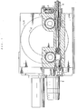
- a prior art turntable provided in universal machine tools of the kind specified above has an indexing mechanism as shown in Fig. 1, which conducts indexing of work to be machined, not shown, (that will be simply referred to as “work” hereinbelow) mounted on the turntable "a” as follows.
- a piston in a clamp cylinder "b" for driving the turntable is actuated in a direction shown by arrow C so as to urge a worm "f” against a worm wheel “e” engaged with a main gear “d” adapted to rotatively drive the turntable “a” to thereby eliminate backlash between the engaged teeth, and then an indexing motor “g” is driven to rotate the main gear “d” through the above-mentioned worm "f” and worm wheel “e” so as to index the work, not shown, on the turntable "a".
- a locking cylinder "h” is actuated to drive a wedge member “i” so as to stop the axial movement of the worm "f” thereby clamping the turntable "a” at the indexing position.
- the above-mentioned prior art indexing mechanism has however the following disadvantage. That is to say, because the driving system includes the worm "f” and the worm wheel “e”, it is necessary to lubricate the worm "f” and the worm wheel “e” with a lubricating oil. Such lubrication needs the use of a lubricating oil having a high viscosity, which generates a considerable amount of heat during high speed running, thus causing a deformation of the turntable "a” due to the heat thus generated, thereby lowering the working accuracy.
- a turntable apparatus and a method are proceeded from as is shown in the GB-A-2 126 314. It is known therefrom to operate the main spindle of a turntable by means of a main drive, wherein an auxiliary drive is used for indexing and controlling rotational positioning of the main spindle. This auxiliary drive additionally serves to reduce or prevent the backlash in the transmission of the main drive. In this manner it shall be made possible to permit a more exact adjustment of the workpiece during the indexing operation.
- the DE-A-1 171 705 shows a possibility of arresting the main spindle of a turntable by means of a locking or fastening means against an unintended rotation during the machining of a workpiece.
- a backlash of the main drive is unavoidable.
- the possibility has not yet been seen to prevent the backlash which is so detrimental to an exact positioning of a workpiece by the arrangement of two drives.
- the method according to claim 3 is made possible to firmly clamp both the main spindle of the turntable as well as the worm shaft of the indexing mechanism driving system in a state in which the backlash of both drive mechanisms has been eliminated.
- a turntable apparatus for use in a universal machine tool arranged such that a lubricating system for lubricating a worm driving system of the indexing mechanism and a lubricating system for lubricating a transmission driving system are provided separately from each other, and the worm driving system is lubricated with a lubricating oil having a high viscosity, whilst the transmission driving system is lubricated with a lubricating oil having a low viscosity.
- Fig. 2 shows a machine tool wherein a base table 2 is mounted on a bed 1 such that it may be moved freely in the directions of X axis and a turntable 3 is mounted on the base table 2 such that it may be rotated freely in the directions shown by arrow C.
- reference numeral 4 denotes a spindle head mounted on the front surface of a column 5 such that it may be moved freely in the directions of Z axis, and 6 an automatic tool exchanging means.
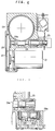
- the above-mentioned main spindle 8 is mounted on the base table 2 in such a way as to be rotated freely through radial ball bearings 9 and a thrust bearing 10 as shown in Fig. 4. Further, the above-mentioned main spindle 8 has a clamping mechanism 11 mounted on the lower end portion thereof.
- the above-mentioned clamping mechanism 11 comprises a disk 11a fixedly secured to the main spindle 8 and having pistons 11b mounted on the upper and lower surfaces thereof.
- the arrangement is made such that the disk 11a is held between these pistons 11b so as to clamp the truntable 3 through the intermediary of the main spindle 8, and each of the pistons 11b is accommodated in a hydraulic cylinder 11c so that they can be driven by fluid under pressure.
- main gear 12 which engages with an output gear 15h of a speed change gear 15.
- the above-mentioned speed change gear 15 is interposed between a turning motor 16 and the above-mentioned main gear 12 so as to change the rotational speed of the turntable 3, and the rotation of the turning motor 16 is input or transmitted through an endless belt 17 to an input shaft 15a of the speed change gear 15.
- the above-mentioned input shaft 15a has a gear 15b which is splined thereto and which engages with a speed change gear 15d fixedly mounted on an intermediate shaft 15c so as to conduct speed change between the gears 15b and 15d.
- the above-mentioned intermediate shaft 15c has a further gear 15e which is mounted fixedly thereon and which engages with a gear 15g fixedly mounted on an output shaft 15f. Further, the aforementioned output gear 15h fixedly mounted on the output shaft 15f is engaged with the above-mentioned main gear 12 so as to rotate the turntable 3 by the turning motor 16 through the intermediary of the main gear 12.
- reference numeral 20 denotes an indexing mechanism having an indexing motor 21 which is comprised of a servomotor which serves to rotate a worm 24 through the intermediary of gears 22 and 23.
- a disk 25 fixedly secured to one end of a shaft 24a of the above-mentioned worm 24 is a disk 25 having a pair of pistons 26 mounted thereon in such a way as to hold or grip it therebetween.
- the above-mentioned pistons 26 are accommodated in a hydraulic cylinder 26a, and the arrangement is made such that fluid under pressure supplied into the hydraulic cylinder 26a causes the pair of pistons 26 to hold or grip the disk 25 therebetween to thereby lock the worm shaft 24a.
- worm 24 is engages with a worm wheel 29 fixedly secured to a rotating shaft 28.
- the above-mentioned worm 24 and the worm wheel 29 are accommodated in a gear casing 30 filled with a lubricating oil having a high viscosity, and the upper end portion of the rotating shaft 28 has a gear 31 which is fixedly mounted thereon and which is engaged through the intermediary of gears 32 and 33, in turn, with the main gear 12.
- the lower end of the rotating shaft 28 is connected by way of a timing belt 34 to a rotational angle detector 35 such as a potentiometer so that an angle of rotation of the turntable 3 can be detected by means of the rotational angle detector 35.
- a rotational angle detector 35 such as a potentiometer
- reference numerals 37 denote oil seals which serve to separate a lubricating oil having a high viscosity for lubricating the worm 24 and the worm wheel 29 from a lubricating oil having a low viscosity for lubricating a pinion gear 38 mounted on a transmission 41 of the indexing mechanism 20 and bearings 39 which support the rotating shaft 28 rotatably so as to reduce the increase in resistance to flow of the lubricating due to stirring thereof during turning of the turntable 3.
- a piston 42 is lowered through the action of fluid pressure so as to allow the pinion gear 38 of the transmission 41 to engage with a gear 44 fixedly secured to the worm wheel 29 to thereby enable the rotation of the indexing motor 21 to be transmitted to the rotating shaft 28.
- the turning motor 16 is rotated with its output torque limited to 10 %, for example in a direction opposite to the rotational direction of the indexing motor so as to rotate the turntable 3 in a direction shown by arrow A, or as shown in Fig. 8, the turning motor 16 is rotated at somewhat higher speed in the same direction as the rotational driection of the indexing motor 21 so as to rotate the turntable 3 in a direction shown by arrow B so that the positioning of the turntable 3 can be made by rotating the same in a condition wherein the backlash in the driving system of the indexing motor 21 has been eliminated.
- the disk 11a fixedly secured to the lower end of the main spindle 8 is held between the upper and lower pistons 11b in such a condition wherein the backlash in the driving system has been eliminated so as to clamp the main spindle 6, and at the same time the disk 25 fixedly secured to one end of the worm shaft 24a is held between the pistons 26 so as to clamp the worm shaft 24a.
- This positioning operation enables the turntable 3 to be locked accurately and securely at a predetermined position, and also the worm shaft 24a is not pushed in the axial direction unlike the prior art turntable apparatus, and there is no possibility of the work getting out of position when it is clamped.
- the indexing/driving system for indexing the turntable is provided separately from the turntable driving system so that the turntable can be indexed by the indexing/driving system while the driving force developed by the turntable driving system is limited during indexing operation, an accurate positioning of the turntable can be made in a condition wherein the backlash in each of the driving systems has been eliminated.
- the arrangement is made such that after the positioning of the turntable the main spindle of the turntable and the indexing shaft of the indexing/driving system are clamped at the same time in a condition wherein the backlash in the driving system, the main spindle and the indexing shaft can be clamped in a pressurized condition so that the turntable can be locked accurately and securely at a predetermined position and also the indexing shaft is not pushed in the axial direction at the time of indexing thereby eliminating the disadvantage that the turntable gets out of position.
- the lubricating system for the worm driving system provided in the indexing mechanism is provided separately from the lubricating system for the transmission driving system and a lubricating oil having a low viscosity is used for the transmission system, such a disadvantage as during working of a work the lubricating oil is heated to cause a thermal deformation of the turntable and the accuracy or working is lowered can be eliminated.
Landscapes
- Engineering & Computer Science (AREA)
- Mechanical Engineering (AREA)
- Machine Tool Positioning Apparatuses (AREA)
- Machine Tool Units (AREA)
Abstract
Description
- This invention relates to a turntable apparatus for use in a universal machine tool, and more particularly to a turntable apparatus and a method for positioning of work mounted on a turntable according to the preambles of
claim 1 and 3 respectively. - A prior art turntable provided in universal machine tools of the kind specified above has an indexing mechanism as shown in Fig. 1, which conducts indexing of work to be machined, not shown, (that will be simply referred to as "work" hereinbelow) mounted on the turntable "a" as follows.
- Upon indexing, first of all, a piston in a clamp cylinder "b" for driving the turntable is actuated in a direction shown by arrow C so as to urge a worm "f" against a worm wheel "e" engaged with a main gear "d" adapted to rotatively drive the turntable "a" to thereby eliminate backlash between the engaged teeth, and then an indexing motor "g" is driven to rotate the main gear "d" through the above-mentioned worm "f" and worm wheel "e" so as to index the work, not shown, on the turntable "a".
- After the indexing of the work, a locking cylinder "h" is actuated to drive a wedge member "i" so as to stop the axial movement of the worm "f" thereby clamping the turntable "a" at the indexing position.
- The above-mentioned prior art indexing mechanism has however the following disadvantage. That is to say, because the driving system includes the worm "f" and the worm wheel "e", it is necessary to lubricate the worm "f" and the worm wheel "e" with a lubricating oil. Such lubrication needs the use of a lubricating oil having a high viscosity, which generates a considerable amount of heat during high speed running, thus causing a deformation of the turntable "a" due to the heat thus generated, thereby lowering the working accuracy.
- Further, even if the indexing position of the work is set accurately, when clamping the turntable "a" by driving the wedge member "i" through the action of the locking cylinder "h" after the indexing, the wedge member "i" is urged towards the worm "f" in the axial direction thereof, thus causing such a disadvantage as changes between the indexing accuracy obtained upon positioning and that obtained upon clamping.
- In the preamble of the
independent claims 1 and 3, a turntable apparatus and a method are proceeded from as is shown in the GB-A-2 126 314. It is known therefrom to operate the main spindle of a turntable by means of a main drive, wherein an auxiliary drive is used for indexing and controlling rotational positioning of the main spindle. This auxiliary drive additionally serves to reduce or prevent the backlash in the transmission of the main drive. In this manner it shall be made possible to permit a more exact adjustment of the workpiece during the indexing operation. - On the other hand the DE-A-1 171 705 shows a possibility of arresting the main spindle of a turntable by means of a locking or fastening means against an unintended rotation during the machining of a workpiece. In this connection it is explicitly emphasized, that a backlash of the main drive is unavoidable. Thus, in this publication the possibility has not yet been seen to prevent the backlash which is so detrimental to an exact positioning of a workpiece by the arrangement of two drives.
- Compared to this prior art it is the object of the invention to provide a turntable apparatus of this type and a method which is capable of preventing the occurrence of changes between the indexing accuracies obtained upon positioning of the workpiece and those obtained upon clamping of the same.
- This object is solved by the features in the respective
independent claims 1 and 3. - By the arrangement of the first clamping means for clamping the main spindle of the turntable and the second clamping means for clamping the indexing shaft of the indexing mechanism driving system, the method according to
claim 3 is made possible to firmly clamp both the main spindle of the turntable as well as the worm shaft of the indexing mechanism driving system in a state in which the backlash of both drive mechanisms has been eliminated. - According to a second aspect of the present invention, there is provided a turntable apparatus for use in a universal machine tool arranged such that a lubricating system for lubricating a worm driving system of the indexing mechanism and a lubricating system for lubricating a transmission driving system are provided separately from each other, and the worm driving system is lubricated with a lubricating oil having a high viscosity, whilst the transmission driving system is lubricated with a lubricating oil having a low viscosity. By this arrangement, the amount of heat generated when working or machining a work can be reduced.
- The above-mentioned and other objects, aspects and advantages of the present invention will become apparent to those skilled in the art from the following detailed description and the accompanying drawings in which a preferred embodiment incorporating the principles of the present invention is shown for example only.
-
- Fig. 1 is a schematic plan view of a prior art embodiment of machine tool including the partial horizontal sectional view thereof;
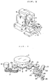
- Fig. 2 is a schematic perspective view of a universal machine tool;
- Fig. 3 is an explanatory view showing a turntable driving system and an indexing mechanism driving system according to one embodiment of the present invention;
- Fig. 4 is an overall longitudinal, sectional view of one embodiment of the present invention;
- Fig. 5 is a schematic plan view of the embodiment shown in Fig. 4 including the partial horizontal sectional view of an indexing motor unit thereof;
- Fig. 6 is a longitudinal sectional view of a worm shaft clamping means of the embodiment shown in Fig. 4; and
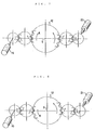
- Figs 7 and 8 are explanatory views showing the operations of the embodiments of the present invention.
- Fig. 2 shows a machine tool wherein a base table 2 is mounted on a bed 1 such that it may be moved freely in the directions of X axis and a
turntable 3 is mounted on the base table 2 such that it may be rotated freely in the directions shown by arrow C. - Further,
reference numeral 4 denotes a spindle head mounted on the front surface of acolumn 5 such that it may be moved freely in the directions of Z axis, and 6 an automatic tool exchanging means. - Whilst, the central portion of the above-mentioned
turntable 3 is fixedly secured to amain spindle 8. - The above-mentioned
main spindle 8 is mounted on the base table 2 in such a way as to be rotated freely throughradial ball bearings 9 and a thrust bearing 10 as shown in Fig. 4. Further, the above-mentionedmain spindle 8 has a clamping mechanism 11 mounted on the lower end portion thereof. - The above-mentioned clamping mechanism 11 comprises a disk 11a fixedly secured to the
main spindle 8 and havingpistons 11b mounted on the upper and lower surfaces thereof. The arrangement is made such that the disk 11a is held between thesepistons 11b so as to clamp the truntable 3 through the intermediary of themain spindle 8, and each of thepistons 11b is accommodated in a hydraulic cylinder 11c so that they can be driven by fluid under pressure. - Further, fixedly secured to the intermediate portion of the above-mentioned
main spindle 8 is amain gear 12 which engages with anoutput gear 15h of aspeed change gear 15. - The above-mentioned
speed change gear 15 is interposed between a turningmotor 16 and the above-mentionedmain gear 12 so as to change the rotational speed of theturntable 3, and the rotation of the turningmotor 16 is input or transmitted through anendless belt 17 to aninput shaft 15a of thespeed change gear 15. - The above-mentioned
input shaft 15a has a gear 15b which is splined thereto and which engages with aspeed change gear 15d fixedly mounted on an intermediate shaft 15c so as to conduct speed change between thegears 15b and 15d. - The above-mentioned intermediate shaft 15c has a
further gear 15e which is mounted fixedly thereon and which engages with agear 15g fixedly mounted on anoutput shaft 15f. Further, theaforementioned output gear 15h fixedly mounted on theoutput shaft 15f is engaged with the above-mentionedmain gear 12 so as to rotate theturntable 3 by the turningmotor 16 through the intermediary of themain gear 12. - Whilst, in the drawings,
reference numeral 20 denotes an indexing mechanism having an indexingmotor 21 which is comprised of a servomotor which serves to rotate aworm 24 through the intermediary ofgears - As shown in Fig. 5, fixedly secured to one end of a shaft 24a of the above-mentioned
worm 24 is adisk 25 having a pair of pistons 26 mounted thereon in such a way as to hold or grip it therebetween. The above-mentioned pistons 26 are accommodated in a hydraulic cylinder 26a, and the arrangement is made such that fluid under pressure supplied into the hydraulic cylinder 26a causes the pair of pistons 26 to hold or grip thedisk 25 therebetween to thereby lock the worm shaft 24a. - Further, the above-mentioned
worm 24 is engages with aworm wheel 29 fixedly secured to a rotating shaft 28. - The above-mentioned
worm 24 and theworm wheel 29 are accommodated in a gear casing 30 filled with a lubricating oil having a high viscosity, and the upper end portion of the rotating shaft 28 has agear 31 which is fixedly mounted thereon and which is engaged through the intermediary ofgears main gear 12. - And, the lower end of the rotating shaft 28 is connected by way of a
timing belt 34 to arotational angle detector 35 such as a potentiometer so that an angle of rotation of theturntable 3 can be detected by means of therotational angle detector 35. - Further, in the drawing, reference numerals 37 denote oil seals which serve to separate a lubricating oil having a high viscosity for lubricating the
worm 24 and theworm wheel 29 from a lubricating oil having a low viscosity for lubricating a pinion gear 38 mounted on atransmission 41 of theindexing mechanism 20 and bearings 39 which support the rotating shaft 28 rotatably so as to reduce the increase in resistance to flow of the lubricating due to stirring thereof during turning of theturntable 3. - In the next place, the operation of the embodiment of the present invention will be described with reference to Figs. 7 and 8. In case indexing of the position of a work, not shown, on the
turntable 3 is made using theturntable 3 as an indexing table, detecting, first of all, the angle of rotation of theturntable 3 by therotational angle detector 35 whileturntable 3 is rotated by the turningmotor 16 through the intermediary of themain gear 12 and transmitting a detection signal, and at the same time indexing the original position of the indexingmotor 21 and transmitting an indexing signal, as shown in Fig. 7, and when coincidence of both the signals is obtained, apiston 42 is lowered through the action of fluid pressure so as to allow the pinion gear 38 of thetransmission 41 to engage with agear 44 fixedly secured to theworm wheel 29 to thereby enable the rotation of the indexingmotor 21 to be transmitted to the rotating shaft 28. - Subsequently, the turning
motor 16 is rotated with its output torque limited to 10 %, for example in a direction opposite to the rotational direction of the indexing motor so as to rotate theturntable 3 in a direction shown by arrow A, or as shown in Fig. 8, the turningmotor 16 is rotated at somewhat higher speed in the same direction as the rotational driection of the indexingmotor 21 so as to rotate theturntable 3 in a direction shown by arrow B so that the positioning of theturntable 3 can be made by rotating the same in a condition wherein the backlash in the driving system of the indexingmotor 21 has been eliminated. - Subsequently, the disk 11a fixedly secured to the lower end of the
main spindle 8 is held between the upper andlower pistons 11b in such a condition wherein the backlash in the driving system has been eliminated so as to clamp themain spindle 6, and at the same time thedisk 25 fixedly secured to one end of the worm shaft 24a is held between the pistons 26 so as to clamp the worm shaft 24a. - This positioning operation enables the
turntable 3 to be locked accurately and securely at a predetermined position, and also the worm shaft 24a is not pushed in the axial direction unlike the prior art turntable apparatus, and there is no possibility of the work getting out of position when it is clamped. - As described hereinabove, according to the present invention, since the indexing/driving system for indexing the turntable is provided separately from the turntable driving system so that the turntable can be indexed by the indexing/driving system while the driving force developed by the turntable driving system is limited during indexing operation, an accurate positioning of the turntable can be made in a condition wherein the backlash in each of the driving systems has been eliminated.
- Since the arrangement is made such that after the positioning of the turntable the main spindle of the turntable and the indexing shaft of the indexing/driving system are clamped at the same time in a condition wherein the backlash in the driving system, the main spindle and the indexing shaft can be clamped in a pressurized condition so that the turntable can be locked accurately and securely at a predetermined position and also the indexing shaft is not pushed in the axial direction at the time of indexing thereby eliminating the disadvantage that the turntable gets out of position.
- Further since the lubricating system for the worm driving system provided in the indexing mechanism is provided separately from the lubricating system for the transmission driving system and a lubricating oil having a low viscosity is used for the transmission system, such a disadvantage as during working of a work the lubricating oil is heated to cause a thermal deformation of the turntable and the accuracy or working is lowered can be eliminated.
Claims (4)
- A turntable apparatus having a turntable (3) in combination with an indexing mechanism (20) for use in a universal machine tool, the turntable (3) having a main spindle (8) comprising:- a turntable driving system for driving the turntable (3),- an indexing mechanism driving system for separately driving said turntable (3), wherein said indexing mechanism is separable from said turntable driving system and has an indexing shaft (24a),
characterized in that,
said apparatus further comprises- first clamping means (11) for clamping said main spindle (8) of said turntable (3) and- second clamping means (25, 26) for clamping said indexing shaft (24a) of said indexing mechanism driving system. - A turntable apparatus according to claim 1,
characterized in that
a lubricating system for lubricating a worm driving system of said indexing mechanism and a lubricating system for lubricating a transmission driving system are provided separately from each other, wherein said worm driving system is lubricated with a lubricating oil having a high viscosity, whilst the transmission driving system is lubricated with a lubricating oil having a low viscosity. - Method for positioning of a work mounted on a turntable which is driven by a turntable apparatus according to claim 1, comprising the method steps:- detecting the rotation angle of said turntable (3) and indexing the original position of said indexing mechanism driving system,- coupling said indexing mechanism driving system with said turntable (3) for driving the latter to rotate while indexing is performed and for limiting of an output torque developed by said turntable driving system, thereby eliminating backlash in both said turntable driving system and said indexing mechanism driving system,- actuating said first clamping means (11) for clamping said main spindle (8) and- actuating said second clamping means (25, 26) after positioning of said turntable (3) for clamping said indexing shaft (24a) of said indexing mechanism driving system in a condition where backlash in each of said driving systems is eliminated.
- Method for positioning of a work according to claim 3, further comprising the step of clamping the main spindle (8) of the turntable (3) and the indexing shaft (24a) of the indexing mechanism driving system at the same time.
Applications Claiming Priority (3)
| Application Number | Priority Date | Filing Date | Title |
|---|---|---|---|
| JP63320469A JP2681818B2 (en) | 1988-12-21 | 1988-12-21 | Turntable device for compound machine tools |
| JP320469/88 | 1988-12-21 | ||
| PCT/JP1989/001288 WO1990006833A1 (en) | 1988-12-21 | 1989-12-21 | Turn table apparatus of composite machine tool |
Publications (3)
| Publication Number | Publication Date |
|---|---|
| EP0450071A1 EP0450071A1 (en) | 1991-10-09 |
| EP0450071A4 EP0450071A4 (en) | 1992-07-08 |
| EP0450071B1 true EP0450071B1 (en) | 1995-08-16 |
Family
ID=18121801
Family Applications (1)
| Application Number | Title | Priority Date | Filing Date |
|---|---|---|---|
| EP90900356A Expired - Lifetime EP0450071B1 (en) | 1988-12-21 | 1989-12-21 | Turn table apparatus of composite machine tool |
Country Status (5)
| Country | Link |
|---|---|
| US (1) | US5188004A (en) |
| EP (1) | EP0450071B1 (en) |
| JP (1) | JP2681818B2 (en) |
| DE (1) | DE68923884T2 (en) |
| WO (1) | WO1990006833A1 (en) |
Families Citing this family (13)
| Publication number | Priority date | Publication date | Assignee | Title |
|---|---|---|---|---|
| JP2967651B2 (en) * | 1991-08-12 | 1999-10-25 | ダイキン工業株式会社 | Positioning device |
| US5386743A (en) * | 1993-07-13 | 1995-02-07 | Industrial Technology Research Institute | Turret indexing device |
| JP3717770B2 (en) * | 2000-08-24 | 2005-11-16 | 津田駒工業株式会社 | Indexing table using multiple lead worms |
| JP2002210634A (en) * | 2001-01-18 | 2002-07-30 | Tsudakoma Corp | Multiple-shaft index table |
| JP2003194156A (en) * | 2001-12-27 | 2003-07-09 | Mori Seiki Co Ltd | Swivel indexing device of machine tool |
| JP2008142874A (en) * | 2006-12-13 | 2008-06-26 | Pascal Engineering Corp | Rotary table and machine tool with same |
| KR101514075B1 (en) * | 2008-12-19 | 2015-04-23 | 두산인프라코어 주식회사 | spindle drive |
| DE202009000086U1 (en) * | 2009-02-05 | 2009-04-02 | Heynau Gearsproductionservice Gmbh | Play-free drive device |
| JP5480187B2 (en) * | 2011-03-25 | 2014-04-23 | 勝彦 横井 | Indexing device |
| CN102950473B (en) * | 2012-11-07 | 2015-11-04 | 南京工大数控科技有限公司 | The NC rotary table of worm gear and gear pair composite flooding and control method thereof |
| DE102017118262A1 (en) * | 2017-08-10 | 2019-02-14 | Weiss Gmbh | ROUND TABLE WITH POWER-OPTIMIZED DRIVE |
| JP6941010B2 (en) * | 2017-08-31 | 2021-09-29 | 株式会社北川鉄工所 | Fluid pressure circuit |
| CN113059397B (en) * | 2021-03-31 | 2022-02-22 | 台丽精密机床(温州)有限公司 | Four-axis revolving stage anchor clamps of sweeps arrangement of being convenient for numerical control lathe machining center |
Citations (3)
| Publication number | Priority date | Publication date | Assignee | Title |
|---|---|---|---|---|
| US3075614A (en) * | 1960-12-08 | 1963-01-29 | John L Grundon | Turntable structure |
| WO1983001752A1 (en) * | 1981-11-23 | 1983-05-26 | Gleason Works | Improved drive train for gear hobbing machine |
| DE3714087A1 (en) * | 1986-05-10 | 1987-11-12 | Volkswagen Ag | Drive assembly with individual lubricating oil circuits for engine and transmission |
Family Cites Families (15)
| Publication number | Priority date | Publication date | Assignee | Title |
|---|---|---|---|---|
| US2972912A (en) * | 1957-11-22 | 1961-02-28 | Gleason Works | Gear cutting machine with work spindle positioning means |
| JPS50113886A (en) * | 1974-02-20 | 1975-09-06 | ||
| US3971293A (en) * | 1975-04-30 | 1976-07-27 | The Gleason Works | Anti-backlash mechanism for generating train of gear cutting machine |
| JPS5565056A (en) * | 1978-11-09 | 1980-05-16 | Komatsu Ltd | Method of indexing rotary body |
| JPS562339U (en) * | 1979-06-15 | 1981-01-10 | ||
| US4325015A (en) * | 1980-05-21 | 1982-04-13 | Danly Machine Corporation | Dual motor drive for machine tool |
| IT1139107B (en) * | 1981-07-22 | 1986-09-17 | Baruffaldi Frizioni Spa | ANGULAR DIVIDING DEVICE FOR WORKPIECE TABLE, TOOL HOLDER OR SIMILAR WITH NON-PREFIXED POSITIONS |
| DE3225195A1 (en) * | 1982-07-06 | 1984-01-12 | J. E. Reinecker Maschinenbau GmbH & Co KG, 7900 Ulm | Relieving lathe |
| GB2126314B (en) * | 1982-09-03 | 1985-09-04 | 600 Group P L C The | Rotating tool turret machine main spindle drive mechanism |
| KR880002215Y1 (en) * | 1986-08-05 | 1988-06-22 | 송병희 | Cleaning brush |
| JPS63120052A (en) * | 1986-11-05 | 1988-05-24 | Om Seisakusho:Kk | Table driving device for composite machining nc vertical lathe |
| US4785513A (en) * | 1986-12-16 | 1988-11-22 | Hardinge Brothers | Turret having rotating and non-rotating tooling |
| JPH0777896B2 (en) * | 1987-08-11 | 1995-08-23 | ニュージャージー・マシーン・インコーポレイテツド | Label sticking apparatus and method |
| GB2242842A (en) * | 1990-04-11 | 1991-10-16 | Chang Kuo Sen | Indexing apparatus |
| US5090267A (en) * | 1990-11-21 | 1992-02-25 | Gramling James T | Indexing apparatus |
-
1988
- 1988-12-21 JP JP63320469A patent/JP2681818B2/en not_active Expired - Lifetime
-
1989
- 1989-12-21 WO PCT/JP1989/001288 patent/WO1990006833A1/en active IP Right Grant
- 1989-12-21 DE DE68923884T patent/DE68923884T2/en not_active Expired - Fee Related
- 1989-12-21 EP EP90900356A patent/EP0450071B1/en not_active Expired - Lifetime
-
1991
- 1991-06-14 US US07/690,891 patent/US5188004A/en not_active Expired - Fee Related
Patent Citations (3)
| Publication number | Priority date | Publication date | Assignee | Title |
|---|---|---|---|---|
| US3075614A (en) * | 1960-12-08 | 1963-01-29 | John L Grundon | Turntable structure |
| WO1983001752A1 (en) * | 1981-11-23 | 1983-05-26 | Gleason Works | Improved drive train for gear hobbing machine |
| DE3714087A1 (en) * | 1986-05-10 | 1987-11-12 | Volkswagen Ag | Drive assembly with individual lubricating oil circuits for engine and transmission |
Also Published As
| Publication number | Publication date |
|---|---|
| DE68923884D1 (en) | 1995-09-21 |
| JP2681818B2 (en) | 1997-11-26 |
| EP0450071A4 (en) | 1992-07-08 |
| DE68923884T2 (en) | 1996-02-08 |
| WO1990006833A1 (en) | 1990-06-28 |
| JPH02167650A (en) | 1990-06-28 |
| US5188004A (en) | 1993-02-23 |
| EP0450071A1 (en) | 1991-10-09 |
Similar Documents
| Publication | Publication Date | Title |
|---|---|---|
| EP0450071B1 (en) | Turn table apparatus of composite machine tool | |
| USRE33732E (en) | Method of machining a workpiece in a turret lathe and an NC lathe for performing this method | |
| KR100256728B1 (en) | Indexing device & index driving method | |
| US4785513A (en) | Turret having rotating and non-rotating tooling | |
| US6016729A (en) | Turret device | |
| US3725987A (en) | Machine tool with spaced turret heads mounted on a cross slide | |
| US6257109B1 (en) | Automatic lathe and method of controlling same | |
| US4087891A (en) | Turret toolposter | |
| GB2167327A (en) | Machining unit with tilting head | |
| JPH022665B2 (en) | ||
| US4413938A (en) | Spindle motor powered drawbar | |
| US4769885A (en) | Eccentric tool rest | |
| US4671712A (en) | Cross slide for a lathe | |
| US4355548A (en) | Tool turret | |
| USRE34155E (en) | Machining a workpiece in a turret lathe and an NC lathe therefor | |
| US4528876A (en) | Universal single spindle pin crankshaft lathe | |
| EP0231085A2 (en) | Machines and housings | |
| JP3139133B2 (en) | Rotary indexing worktable device | |
| EP3784427B1 (en) | High-performance facing head | |
| SU933297A1 (en) | Milling nozzle | |
| SU921819A1 (en) | Apparatus for turning grinding head | |
| JP2557002Y2 (en) | Tool post of compound NC lathe | |
| GB2212753A (en) | Machine tool turret assembly | |
| JPH08112703A (en) | Headstock and metal working machine tool | |
| KR0152720B1 (en) | Tool turret driving device for cnc lathe |
Legal Events
| Date | Code | Title | Description |
|---|---|---|---|
| PUAI | Public reference made under article 153(3) epc to a published international application that has entered the european phase |
Free format text: ORIGINAL CODE: 0009012 |
|
| 17P | Request for examination filed |
Effective date: 19910619 |
|
| AK | Designated contracting states |
Kind code of ref document: A1 Designated state(s): CH DE GB IT LI |
|
| A4 | Supplementary search report drawn up and despatched |
Effective date: 19920520 |
|
| AK | Designated contracting states |
Kind code of ref document: A4 Designated state(s): CH DE GB IT LI |
|
| 17Q | First examination report despatched |
Effective date: 19921026 |
|
| GRAA | (expected) grant |
Free format text: ORIGINAL CODE: 0009210 |
|
| AK | Designated contracting states |
Kind code of ref document: B1 Designated state(s): CH DE GB IT LI |
|
| ITF | It: translation for a ep patent filed | ||
| REF | Corresponds to: |
Ref document number: 68923884 Country of ref document: DE Date of ref document: 19950921 |
|
| PLBE | No opposition filed within time limit |
Free format text: ORIGINAL CODE: 0009261 |
|
| STAA | Information on the status of an ep patent application or granted ep patent |
Free format text: STATUS: NO OPPOSITION FILED WITHIN TIME LIMIT |
|
| 26N | No opposition filed | ||
| PGFP | Annual fee paid to national office [announced via postgrant information from national office to epo] |
Ref country code: GB Payment date: 19981224 Year of fee payment: 10 |
|
| PGFP | Annual fee paid to national office [announced via postgrant information from national office to epo] |
Ref country code: CH Payment date: 19990115 Year of fee payment: 10 |
|
| PG25 | Lapsed in a contracting state [announced via postgrant information from national office to epo] |
Ref country code: GB Free format text: LAPSE BECAUSE OF NON-PAYMENT OF DUE FEES Effective date: 19991221 |
|
| PGFP | Annual fee paid to national office [announced via postgrant information from national office to epo] |
Ref country code: DE Payment date: 19991230 Year of fee payment: 11 |
|
| PG25 | Lapsed in a contracting state [announced via postgrant information from national office to epo] |
Ref country code: LI Free format text: LAPSE BECAUSE OF NON-PAYMENT OF DUE FEES Effective date: 19991231 Ref country code: CH Free format text: LAPSE BECAUSE OF NON-PAYMENT OF DUE FEES Effective date: 19991231 |
|
| GBPC | Gb: european patent ceased through non-payment of renewal fee |
Effective date: 19991221 |
|
| PG25 | Lapsed in a contracting state [announced via postgrant information from national office to epo] |
Ref country code: DE Free format text: LAPSE BECAUSE OF NON-PAYMENT OF DUE FEES Effective date: 20011002 |
|
| PG25 | Lapsed in a contracting state [announced via postgrant information from national office to epo] |
Ref country code: IT Free format text: LAPSE BECAUSE OF NON-PAYMENT OF DUE FEES;WARNING: LAPSES OF ITALIAN PATENTS WITH EFFECTIVE DATE BEFORE 2007 MAY HAVE OCCURRED AT ANY TIME BEFORE 2007. THE CORRECT EFFECTIVE DATE MAY BE DIFFERENT FROM THE ONE RECORDED. Effective date: 20051221 |