EP0448991A2 - Echangeur de chaleur - Google Patents
Echangeur de chaleur Download PDFInfo
- Publication number
- EP0448991A2 EP0448991A2 EP91103179A EP91103179A EP0448991A2 EP 0448991 A2 EP0448991 A2 EP 0448991A2 EP 91103179 A EP91103179 A EP 91103179A EP 91103179 A EP91103179 A EP 91103179A EP 0448991 A2 EP0448991 A2 EP 0448991A2
- Authority
- EP
- European Patent Office
- Prior art keywords
- heat exchanger
- exchanger according
- elements
- intermediate layer
- profile
- Prior art date
- Legal status (The legal status is an assumption and is not a legal conclusion. Google has not performed a legal analysis and makes no representation as to the accuracy of the status listed.)
- Granted
Links
Images


Classifications
-
- F—MECHANICAL ENGINEERING; LIGHTING; HEATING; WEAPONS; BLASTING
- F28—HEAT EXCHANGE IN GENERAL
- F28F—DETAILS OF HEAT-EXCHANGE AND HEAT-TRANSFER APPARATUS, OF GENERAL APPLICATION
- F28F3/00—Plate-like or laminated elements; Assemblies of plate-like or laminated elements
- F28F3/005—Arrangements for preventing direct contact between different heat-exchange media
-
- F—MECHANICAL ENGINEERING; LIGHTING; HEATING; WEAPONS; BLASTING
- F28—HEAT EXCHANGE IN GENERAL
- F28D—HEAT-EXCHANGE APPARATUS, NOT PROVIDED FOR IN ANOTHER SUBCLASS, IN WHICH THE HEAT-EXCHANGE MEDIA DO NOT COME INTO DIRECT CONTACT
- F28D9/00—Heat-exchange apparatus having stationary plate-like or laminated conduit assemblies for both heat-exchange media, the media being in contact with different sides of a conduit wall
- F28D9/0062—Heat-exchange apparatus having stationary plate-like or laminated conduit assemblies for both heat-exchange media, the media being in contact with different sides of a conduit wall the conduits for one heat-exchange medium being formed by spaced plates with inserted elements
-
- F—MECHANICAL ENGINEERING; LIGHTING; HEATING; WEAPONS; BLASTING
- F28—HEAT EXCHANGE IN GENERAL
- F28F—DETAILS OF HEAT-EXCHANGE AND HEAT-TRANSFER APPARATUS, OF GENERAL APPLICATION
- F28F3/00—Plate-like or laminated elements; Assemblies of plate-like or laminated elements
- F28F3/02—Elements or assemblies thereof with means for increasing heat-transfer area, e.g. with fins, with recesses, with corrugations
- F28F3/025—Elements or assemblies thereof with means for increasing heat-transfer area, e.g. with fins, with recesses, with corrugations the means being corrugated, plate-like elements
-
- F—MECHANICAL ENGINEERING; LIGHTING; HEATING; WEAPONS; BLASTING
- F28—HEAT EXCHANGE IN GENERAL
- F28F—DETAILS OF HEAT-EXCHANGE AND HEAT-TRANSFER APPARATUS, OF GENERAL APPLICATION
- F28F2215/00—Fins
- F28F2215/10—Secondary fins, e.g. projections or recesses on main fins
Definitions
- the invention relates to a heat exchanger for exchanging heat between two separate media, consisting of at least one heat exchanger module with connecting and connecting elements, with layered profile elements in sandwich construction and intermediate layer elements for separating the different flow directions, the side walls of the profile elements and the intermediate layer elements each one Form flow chamber and common lines of contact and the edge areas are sealed by end strips and the modules by end plates.
- Heat exchangers are required, for example, to exchange heat with the same or different media in order to carry out heat recovery or heat transfer. From today's environmental perspective, this process is becoming increasingly important and is required in a variety of ways in industry. It may also be necessary under certain circumstances that the greatest safety precautions can be taken with aggressive or reacting media.
- CH-PS 193 732 a device for heat exchange of flowing media is known, which has a crossed sandwich structure of flat and corrugated leaves.
- the interleaf sheets can be reinforced by embossing and are held together with the corrugated sheets by external contact angles.
- a heat exchanger which is constructed from flexible plastic films as storage chambers. These are closed at the edge and a suitable heat-exchanging medium flows through corresponding connection elements. In the inflated state, these plastic films form a flat, hollow-plate-like element which is arranged in a flow around it by a further medium.
- a disadvantage of these two types of heat exchangers is the low permissible pressure difference between the heat-emitting and heat-absorbing medium. Furthermore, the efficiency of the heat exchanger is very limited and in need of improvement. Due to the simply designed partition walls, use with high security requirements such as excluded with toxic, aggressive or expensive media.
- the invention is therefore based on the object of providing a heat exchanger which has a high degree of efficiency and a low weight and can be used for high pressures and, where appropriate, meets high safety requirements, and also specifies a method for its production.
- the thin-walled profile elements are folded in a zigzag shape and the side walls of adjacent flow chambers of the profile elements and / or the thin-walled intermediate layer elements have curvatures to one or two adjacent flow chamber (s) and that the profile and intermediate layer elements are connected to one another at their respective contact lines.
- the special shape of the zigzag-shaped profile elements results in an extremely stable structure, the walls of the profile elements being reinforced by curvatures and having great rigidity absorb large pressure and buckling forces.
- the intermediate layer elements separate the different media from each other, which flow in the crossed profile elements and are also reinforced by bulges. These measures allow the heat exchanger to be made from extremely thin-walled sheets. Furthermore, the heat and transmission areas are increased by the curvatures and the resulting turbulence in the profile chambers results in an increase in the Reynold number and thus an increase in the k value, so that the heat exchanger has a large ratio between the exchange surface and the space requirement and Efficiency of the heat exchanger is significantly improved.
- the contacting surfaces and lines of the profile and intermediate layer elements are connected to one another, it is also possible to allow a high pressure load by the media, which are separated from the intermediate layer elements.
- the necessary security requirements for high-risk media are met in that the intermediate layer elements are made of two layers.
- the curvatures of the profile elements and intermediate layer elements can in this case be arranged transversely or in the direction of flow, the curvatures of the intermediate layer elements being arranged on one side or alternating with the profile elements and the curvatures of the profile elements being wave-shaped. In special cases, the formation of beads in the profile element walls is provided.
- the shapes of the intermediate layer elements can be chosen to be elongated, spherical or pyramid-shaped.
- the profile elements are layered crosswise rotated by 90 degrees, so that good heat transfer is achieved as a cross-flow heat exchanger.
- the flow chambers of the profile elements one Flow plane are angled in a U-shape, the middle region and the angled end regions each being stacked in parallel with the other flow chambers.
- the course of the flow direction can be chosen in the same direction or in opposite directions.
- This configuration and arrangement of the profile elements creates a countercurrent heat exchanger in the second case, which has a further improved efficiency.
- the intermediate layer elements are made of two layers and the arches are arranged one inside the other.
- the double-layer design of the intermediate layer elements meets the safety requirements. Wherever toxic, aggressive or very expensive products require increased safety technology for heat transfer, a complex construction of this type is justified.
- the basic module with increased security technology is constructed with the same construction elements as the normal module, whereby only two intermediate layer elements are used and the edges of these elements are tightly connected. This creates an intermediate space that catches the medium in the event of any leaks in one or the other flow level and can generate a corresponding warning message, for example, via a leak detector.
- the spaces formed by the double-layer intermediate layer elements are connected to one another via side boundary profiles which have at least one connecting channel.
- the connecting channel Through the connecting channel, all or part of the spaces are connected to each other, i. H. it is possible to monitor the gaps with one or more common leak detection devices.
- Arises on an intermediate layer element e.g. a leak the medium can get from the profile chambers into the space and from there via the channel or channels to the leak detector.
- the connection to a collecting container can be made on the channels of the side boundary profile via a connected pipeline, this container being equipped with a leak indicator.
- the container and the channel system can be placed under vacuum. After reaching the final pressure, the vacuum connection is welded, so that the container and the channels thus remain under vacuum until the intermediate layer elements are damaged. The heat transfer is maintained here by the connection of the intermediate layer elements.
- the heat exchanger remains fully functional even if an intermediate layer element is damaged and the damage is indicated in good time by the warning via the leak indicator.
- the crossed profile elements can have different heights so that the heat exchanger modules can be used not only as a heat exchanger but also as a heat store. Tolerance compensation of the profile elements or of the different heights can be achieved, for example, by triangular strips that can be pushed together and connected.
- the profile planes of a flow direction are designed to be correspondingly high in heat stores, so that a larger amount of heat-absorbing materials can be embedded.
- a liquid or gaseous medium can flow through the low-profile profile level for heating or cooling, which, for example, emits its heat to the storage medium when it is heated and is heated again after the storage medium has cooled.
- Paraffin or Glauber's salt for example, can be used as storage media.
- the surfaces that are touched by these media can be electropolished.
- a heat exchanger is constructed using modules that can be connected to one another via pipe segments.
- the pipe segments are used on the one hand as connecting elements between the profile planes and have disks in the pipe segments which serve to direct the flow and, on the other hand, the pipe segments stiffen or reinforce the entire structure of the heat exchanger.
- further attached pipe segment quarters and ribs are provided, which increase the stiffening of the housing.
- the pipe segments are provided with flattened connecting pipes and connecting elements so that a flow circuit of the media can be realized.
- Metallic materials are preferably used to manufacture the heat exchangers with profile elements, intermediate layer elements, end plates and triangular strips.
- a method for producing a heat exchanger according to one or more of the features already mentioned before that the profile, intermediate layer elements, end plates and end strips, as well as contact lines and / or surfaces of the sandwich structure are welded to one another, in particular by means of hidden seams, completely, point-by-point or at intervals.
- the intermediate layer elements are also welded to one another point by point around the bulges. It is also provided that the triangular end strips are welded.
- the welding process is carried out by means of an electron beam, laser and / or plasma welding process with a low energy transfer in order to weld the structure in a stress-free, smooth and distortion-free manner.
- welding is carried out under vacuum or inert gas blanketing.
- the profile elements 2 consist of a zigzag-folded sheet, which is provided on the side walls 18 with curvatures 4.
- the curvatures 4 are arranged transversely to the flow direction A, B and consist of corrugated impressions or beads.
- the height of the profile elements 2 for use as a heat exchanger between two different or the same media in both flow directions A, B is the same and in Fig. 2, the height of the profile elements 2 for use as a heat store between two different media designed differently in both flow directions A, B.
- the intermediate layer elements 3 are flush with the profile elements 2 on the end faces 5, 6 and separate the two flow directions A, B from each other.
- the intermediate layer elements 3 also have bulges 8, which consist of elongated, spherical or pyramid-shaped impressions.
- the lines of contact 16 of the profile 2 and intermediate layer elements 3 are welded together for reasons of stability.
- the lateral termination of the profile elements 2 parallel to the flow direction A, B is carried out by end strips 9, which have a square cross section and are tightly welded to one another and to the intermediate layer elements 3 in the corner points 10.
- the upper and lower profile level is sealed by a tightly welded end plate 11, so that a basic module is formed which has flow directions A, B offset by 90 °, so that the media through the flow chambers 7 in the direction A, A 'and B, B 'can flow.
- the existing curvatures 4, 8 swirl the media and thus improve the efficiency of the heat exchanger.
- rectangular end strips 9 are used to complete the higher profile levels.
- Figure 3 shows an heat exchanger 1 in an exploded view, which has an elongated extension compared to Figures 1 and 2 and is equipped with profile elements 2 which are angled in a U-shape.
- the middle region of the profile elements 2 and the angled end regions 12 are layered in such a way that the flow chambers 7 of each plane run parallel, the flow chambers 7 of the individual flow planes being flowed through in opposite directions, so that the principle of a countercurrent heat exchanger is achieved.
- the two openings of the angled end regions 12 of the flow directions A, A 'and B, B' each point to a longitudinal side of the heat exchanger 1 and allow the two media to flow in and out.
- FIGS. 4 and 5 each show an exploded view of the heat exchanger 1, from which the structure can be seen particularly clearly.
- An intermediate layer element 3 and a profile element 2 with lateral end strips 9 are alternately arranged on the square end plate 11, both elements 2, 3 being provided with curvatures 4, 8 in the form of beads or elongated or spherical impressions.
- the intermediate layer element 3 in this case has spherical impressions in the center of the surface and elongated impressions on the two edges towards the end strip 9.
- the end strips 9 consist of two triangular strips 20 which are displaceable relative to one another and are used for tolerance and height compensation of the profile elements 2. All components of the heat exchanger 1 are welded, the contact lines 16 and surfaces 19 located at the edge in particular being tightly welded.
- the intermediate layer elements 3 are double-layered and layered with the curvatures 8 so that a high safety standard is achieved.
- FIGS. 6 and 7 three intermediate layer elements 3 and two profile elements 2 are shown in an enlarged and partially openwork representation.
- the spherical impressions in the intermediate layer elements 3 and the wave-shaped impressions or the beads in the walls 18 of the profile elements 2 can be seen very well.
- the lines of contact 16 of the individual elements 2, 3 are spot welded or fully welded.
- additional wave-shaped turbulators 17 are welded into the flow chambers 7, which lead to a further swirling of the media and thus to a further improvement in the efficiency.
- the turbulators 17 are spot welded to the folded profile element 2 and protrude into the flow chamber 7, the turbulators 17 also being corrugated.
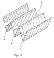
- FIG. 8 shows a single profile element 2, which is folded in a zigzag shape and has elongated beads on the walls 18.
- FIG. 9 shows an intermediate layer element 3 which has alternative embodiments of the curvatures 8 in the form of elongated, spherical and pyramid-shaped impressions. These impressions can be aligned alternately to the two adjacent profile elements 2.
- FIG. 11 shows three modules of the heat exchanger 1 which are arranged next to one another and are connected to a tube segment 21 which is semicircular with the flat open side 22 against the modules and is welded to them.
- the pipe segment 21 is closed with an end piece 23.
- FIG. 12 shows three modules of the heat exchanger 1 in a sectional side view with two tube segments 21 which rest with their flat open sides 22 on the end faces 5, 6 of the heat exchanger 1.
- the pipe segments 21 serve as inlet and outlet pipes 28 and have at their ends connection flanges 24 which serve to connect the inlet and outlet lines.
- disks 25 are arranged, which are used to direct the flow of the medium.
- FIG. 13 shows a compact and complete heat exchanger 1, each with two inlet and outlet pipe segments 21, each pipe segment 21 being connected flat to the module and each having a connecting flange 24.
- the flow directions are identified by A, A 'and B, B'.
- the pipe segments 21 are welded to one another by further pipe segment quarters 26 and reinforce and stiffen the heat exchanger 1.
- FIG. 14 shows the attachment of the attached tube segment quarters 26 to the tube segments 21 again in a sectional drawing.
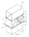
- FIG. 15 shows two modules with a tube segment 21 and a connecting flange 24, with additional reinforcement of the construction being brought about by ribs 27.
- FIGS. 16 a - d each show a heat exchanger 1, which is constructed from one or more modules with connecting elements in the form of tube segments 21 and connecting flanges 24. While FIG. 16a is based on one module, in FIG. 16b there are three modules arranged side by side and in FIG. 16c six modules, three of them side by side and two each one above the other. FIG. 16d shows twelve modules, each of which is arranged three in a row in a package of four and is equipped with double connecting segments 21 and connecting flanges 24.
Landscapes
- Engineering & Computer Science (AREA)
- Physics & Mathematics (AREA)
- Thermal Sciences (AREA)
- Mechanical Engineering (AREA)
- General Engineering & Computer Science (AREA)
- Heat-Exchange Devices With Radiators And Conduit Assemblies (AREA)
- Separation By Low-Temperature Treatments (AREA)
- Power Steering Mechanism (AREA)
- Compression-Type Refrigeration Machines With Reversible Cycles (AREA)
Applications Claiming Priority (2)
| Application Number | Priority Date | Filing Date | Title |
|---|---|---|---|
| DE4009556A DE4009556C2 (de) | 1990-03-24 | 1990-03-24 | Wärmeübertrager |
| DE4009556 | 1990-03-24 |
Publications (3)
| Publication Number | Publication Date |
|---|---|
| EP0448991A2 true EP0448991A2 (fr) | 1991-10-02 |
| EP0448991A3 EP0448991A3 (en) | 1992-05-06 |
| EP0448991B1 EP0448991B1 (fr) | 1994-06-01 |
Family
ID=6403013
Family Applications (1)
| Application Number | Title | Priority Date | Filing Date |
|---|---|---|---|
| EP91103179A Expired - Lifetime EP0448991B1 (fr) | 1990-03-24 | 1991-03-02 | Echangeur de chaleur |
Country Status (3)
| Country | Link |
|---|---|
| EP (1) | EP0448991B1 (fr) |
| AT (1) | ATE106540T1 (fr) |
| DE (2) | DE4009556C2 (fr) |
Cited By (24)
| Publication number | Priority date | Publication date | Assignee | Title |
|---|---|---|---|---|
| FR2780772A1 (fr) * | 1998-07-02 | 2000-01-07 | Packinox Sa | Echangeur de chaleur a plaques pour une installation de cristallisation et procede de cristallisation |
| EP1239252A1 (fr) * | 2001-03-08 | 2002-09-11 | Sanden Corporation | Echangeur de chaleur du type empilé à passage multiple |
| EP1398593A2 (fr) | 2002-09-13 | 2004-03-17 | Air Products And Chemicals, Inc. | Echangeur de chaleur à plaques et ailettes avec surfaces texturées |
| EP2972046A4 (fr) * | 2013-03-14 | 2016-11-30 | Nortek Air Solutions Canada Inc | Ensemble d'échange d'énergie intégrant une membrane |
| EP3098554A4 (fr) * | 2014-02-14 | 2017-02-22 | Sumitomo Precision Products Co., Ltd. | Échangeur de chaleur à ailettes en plaque et procédé de fabrication pour ailettes ondulées d'échangeur de chaleur |
| US9810439B2 (en) | 2011-09-02 | 2017-11-07 | Nortek Air Solutions Canada, Inc. | Energy exchange system for conditioning air in an enclosed structure |
| US9816760B2 (en) | 2012-08-24 | 2017-11-14 | Nortek Air Solutions Canada, Inc. | Liquid panel assembly |
| US9909768B2 (en) | 2013-03-13 | 2018-03-06 | Nortek Air Solutions Canada, Inc. | Variable desiccant control energy exchange system and method |
| US9920960B2 (en) | 2011-01-19 | 2018-03-20 | Nortek Air Solutions Canada, Inc. | Heat pump system having a pre-processing module |
| CN108662927A (zh) * | 2017-04-01 | 2018-10-16 | 天津华赛尔传热设备有限公司 | 一种板式气气换热器 |
| US10302317B2 (en) | 2010-06-24 | 2019-05-28 | Nortek Air Solutions Canada, Inc. | Liquid-to-air membrane energy exchanger |
| CN109891177A (zh) * | 2016-10-27 | 2019-06-14 | 林德股份公司 | 板式热交换器 |
| US10584884B2 (en) | 2013-03-15 | 2020-03-10 | Nortek Air Solutions Canada, Inc. | Control system and method for a liquid desiccant air delivery system |
| US10634392B2 (en) | 2013-03-13 | 2020-04-28 | Nortek Air Solutions Canada, Inc. | Heat pump defrosting system and method |
| EP3644007A1 (fr) * | 2018-10-24 | 2020-04-29 | L'air Liquide, Societe Anonyme Pour L'etude Et L'exploitation Des Procedes Georges Claude | Procédé pour la fabrication d'une série d'au moins un premier et un deuxième échangeurs de chaleur |
| EP3644006A1 (fr) * | 2018-10-24 | 2020-04-29 | L'air Liquide, Societe Anonyme Pour L'etude Et L'exploitation Des Procedes Georges Claude | Procédé pour la fabrication d'une série d'au moins un premier et un deuxième échangeurs de chaleur |
| US10712024B2 (en) | 2014-08-19 | 2020-07-14 | Nortek Air Solutions Canada, Inc. | Liquid to air membrane energy exchangers |
| US10782045B2 (en) | 2015-05-15 | 2020-09-22 | Nortek Air Solutions Canada, Inc. | Systems and methods for managing conditions in enclosed space |
| US10808951B2 (en) | 2015-05-15 | 2020-10-20 | Nortek Air Solutions Canada, Inc. | Systems and methods for providing cooling to a heat load |
| US10962252B2 (en) | 2015-06-26 | 2021-03-30 | Nortek Air Solutions Canada, Inc. | Three-fluid liquid to air membrane energy exchanger |
| US11092349B2 (en) | 2015-05-15 | 2021-08-17 | Nortek Air Solutions Canada, Inc. | Systems and methods for providing cooling to a heat load |
| US11408681B2 (en) | 2013-03-15 | 2022-08-09 | Nortek Air Solations Canada, Iac. | Evaporative cooling system with liquid-to-air membrane energy exchanger |
| EP4306891A1 (fr) * | 2022-07-12 | 2024-01-17 | RTX Corporation | Échangeur de chaleur à passage d'écoulement triangulaire |
| US11892193B2 (en) | 2017-04-18 | 2024-02-06 | Nortek Air Solutions Canada, Inc. | Desiccant enhanced evaporative cooling systems and methods |
Families Citing this family (7)
| Publication number | Priority date | Publication date | Assignee | Title |
|---|---|---|---|---|
| DE4129598A1 (de) * | 1991-09-06 | 1993-03-11 | Ruhrgas Ag | Verfahren und vorrichtung zum steigern des waermeuebergangs zwischen einer wand und einem waermetraegerfluid |
| DE4431413C2 (de) * | 1994-08-24 | 2002-10-10 | Rehberg Michael | Plattenwärmetauscher für flüssige und gasförmige Medien |
| DE4433659C1 (de) * | 1994-09-21 | 1995-12-07 | Colibri Bv | Plattenwärmetauscher |
| DE4438393A1 (de) * | 1994-10-27 | 1996-05-02 | Schmidt Bretten Gmbh | Verfahren zum Verschweißen je zweier benachbarter Platten eines Plattenwärmeaustauschers sowie nach dem Verfahren hergestellter Plattenwärmeaustauscher |
| DE19933426C2 (de) * | 1999-07-16 | 2002-11-14 | Christoph Schmid | Wärmetauschermodul |
| DE10234771B4 (de) * | 2002-07-30 | 2004-08-26 | Rauschert Verfahrenstechnik Gmbh | Wärmespeicherbett für regenerative Wärmeübertragung |
| DE102010019369A1 (de) * | 2010-05-05 | 2011-11-10 | Mahle International Gmbh | Kühleinrichtung |
Citations (13)
| Publication number | Priority date | Publication date | Assignee | Title |
|---|---|---|---|---|
| US2170484A (en) * | 1937-02-13 | 1939-08-22 | Prat Emile | Heat interchanger |
| US2640194A (en) * | 1948-07-16 | 1953-05-26 | Separator Ab | Plate heat exchanger |
| US3372743A (en) * | 1967-01-25 | 1968-03-12 | Pall Corp | Heat exchanger |
| DE1805208A1 (de) * | 1968-01-15 | 1969-10-16 | Augsburg Nuernberg Ag Zweignie | Kreuzstrom-Plattenwaermetauscher |
| US3513907A (en) * | 1968-04-17 | 1970-05-26 | United Aircraft Prod | Plural mode heat exchange apparatus |
| FR2085173A1 (en) * | 1969-12-24 | 1971-12-24 | Nord Aviat | Monobloc heat exchanger prodn - esp for aircraft cabin air conditioner circuits |
| US3633661A (en) * | 1970-08-14 | 1972-01-11 | Trane Co | Crossflow plate-type heat exchanger with barrier space |
| GB1395013A (en) * | 1972-11-22 | 1975-05-21 | Apv Co Ltd | Plate heat exchangers |
| DE3003573A1 (de) * | 1980-02-01 | 1981-10-08 | geb.Wagner Vera 5202 Hennef Schmidt | Waermetauscherelement in paketform |
| DE3017082A1 (de) * | 1980-05-03 | 1981-11-05 | Gea Ahlborn Gmbh & Co Kg, 3203 Sarstedt | Waermeaustauscherplatte |
| FR2566306A1 (fr) * | 1984-06-26 | 1985-12-27 | Brun Michel | Procede de realisation d'echangeurs de chaleur par soudage laser |
| JPS63267889A (ja) * | 1987-04-27 | 1988-11-04 | Nippon Oil Co Ltd | 直交流型熱交換器用伝熱エレメントブロツク |
| SU1575063A1 (ru) * | 1988-09-28 | 1990-06-30 | Н.А.Симоненко | Пакет пластинчатого теплообменника |
Family Cites Families (9)
| Publication number | Priority date | Publication date | Assignee | Title |
|---|---|---|---|---|
| CH193732A (de) * | 1935-07-10 | 1937-10-31 | Hans Dr Behringer | Vorrichtung, in welcher strömende Medien zur Durchführung einer isobaren thermodynamischen Zustandsänderung in Berührung mit Wänden gebracht werden. |
| GB488571A (en) * | 1937-01-09 | 1938-07-11 | Andrew Swan | Improvements in plate heat exchangers for fluids |
| CH610648A5 (en) * | 1976-09-21 | 1979-04-30 | Sulzer Ag | Heat exchanger, in particular for ventilating equipment |
| SE423750B (sv) * | 1977-01-14 | 1982-05-24 | Munters Ab Carl | Anordning vid vermevexlare for sensibel och/eller latent vermeoverforing |
| DE3106075C2 (de) * | 1981-02-19 | 1984-10-04 | Dieter Christian Steinegg-Appenzell Steeb | Wärmetauscher |
| GB2132748B (en) * | 1982-12-24 | 1986-04-30 | Terence Peter Nicholson | Improvements relating to heat exchangers |
| DE3300523A1 (de) * | 1983-01-10 | 1984-07-12 | Funke Wärmeaustauscher Apparatebau KG, 3212 Gronau | Plattenwaermeaustauscher |
| DE3521914A1 (de) * | 1984-06-20 | 1986-01-02 | Showa Aluminum Corp., Sakai, Osaka | Waermetauscher in fluegelplattenbauweise |
| FR2575279B1 (fr) * | 1984-12-21 | 1989-07-07 | Barriquand | Echangeur a plaques |
-
1990
- 1990-03-24 DE DE4009556A patent/DE4009556C2/de not_active Expired - Fee Related
-
1991
- 1991-03-02 EP EP91103179A patent/EP0448991B1/fr not_active Expired - Lifetime
- 1991-03-02 DE DE59101745T patent/DE59101745D1/de not_active Expired - Fee Related
- 1991-03-02 AT AT91103179T patent/ATE106540T1/de not_active IP Right Cessation
Patent Citations (13)
| Publication number | Priority date | Publication date | Assignee | Title |
|---|---|---|---|---|
| US2170484A (en) * | 1937-02-13 | 1939-08-22 | Prat Emile | Heat interchanger |
| US2640194A (en) * | 1948-07-16 | 1953-05-26 | Separator Ab | Plate heat exchanger |
| US3372743A (en) * | 1967-01-25 | 1968-03-12 | Pall Corp | Heat exchanger |
| DE1805208A1 (de) * | 1968-01-15 | 1969-10-16 | Augsburg Nuernberg Ag Zweignie | Kreuzstrom-Plattenwaermetauscher |
| US3513907A (en) * | 1968-04-17 | 1970-05-26 | United Aircraft Prod | Plural mode heat exchange apparatus |
| FR2085173A1 (en) * | 1969-12-24 | 1971-12-24 | Nord Aviat | Monobloc heat exchanger prodn - esp for aircraft cabin air conditioner circuits |
| US3633661A (en) * | 1970-08-14 | 1972-01-11 | Trane Co | Crossflow plate-type heat exchanger with barrier space |
| GB1395013A (en) * | 1972-11-22 | 1975-05-21 | Apv Co Ltd | Plate heat exchangers |
| DE3003573A1 (de) * | 1980-02-01 | 1981-10-08 | geb.Wagner Vera 5202 Hennef Schmidt | Waermetauscherelement in paketform |
| DE3017082A1 (de) * | 1980-05-03 | 1981-11-05 | Gea Ahlborn Gmbh & Co Kg, 3203 Sarstedt | Waermeaustauscherplatte |
| FR2566306A1 (fr) * | 1984-06-26 | 1985-12-27 | Brun Michel | Procede de realisation d'echangeurs de chaleur par soudage laser |
| JPS63267889A (ja) * | 1987-04-27 | 1988-11-04 | Nippon Oil Co Ltd | 直交流型熱交換器用伝熱エレメントブロツク |
| SU1575063A1 (ru) * | 1988-09-28 | 1990-06-30 | Н.А.Симоненко | Пакет пластинчатого теплообменника |
Non-Patent Citations (1)
| Title |
|---|
| PATENT ABSTRACTS OF JAPAN vol. 13, no. 65 (M-797)(3413) 14. Februar 1989 & JP-A-63 267 889 ( NIPPON OIL CO LTD ) 4. November 1988 * |
Cited By (41)
| Publication number | Priority date | Publication date | Assignee | Title |
|---|---|---|---|---|
| FR2780772A1 (fr) * | 1998-07-02 | 2000-01-07 | Packinox Sa | Echangeur de chaleur a plaques pour une installation de cristallisation et procede de cristallisation |
| EP1239252A1 (fr) * | 2001-03-08 | 2002-09-11 | Sanden Corporation | Echangeur de chaleur du type empilé à passage multiple |
| EP1398593A2 (fr) | 2002-09-13 | 2004-03-17 | Air Products And Chemicals, Inc. | Echangeur de chaleur à plaques et ailettes avec surfaces texturées |
| EP1398593A3 (fr) * | 2002-09-13 | 2008-05-28 | Air Products And Chemicals, Inc. | Echangeur de chaleur à plaques et ailettes avec surfaces texturées |
| EP1398593B1 (fr) | 2002-09-13 | 2016-02-03 | Air Products And Chemicals, Inc. | Echangeur de chaleur à plaques et ailettes avec surfaces texturées |
| US10302317B2 (en) | 2010-06-24 | 2019-05-28 | Nortek Air Solutions Canada, Inc. | Liquid-to-air membrane energy exchanger |
| US9920960B2 (en) | 2011-01-19 | 2018-03-20 | Nortek Air Solutions Canada, Inc. | Heat pump system having a pre-processing module |
| US10928082B2 (en) | 2011-09-02 | 2021-02-23 | Nortek Air Solutions Canada, Inc. | Energy exchange system for conditioning air in an enclosed structure |
| US9810439B2 (en) | 2011-09-02 | 2017-11-07 | Nortek Air Solutions Canada, Inc. | Energy exchange system for conditioning air in an enclosed structure |
| US11761645B2 (en) | 2011-09-02 | 2023-09-19 | Nortek Air Solutions Canada, Inc. | Energy exchange system for conditioning air in an enclosed structure |
| US9816760B2 (en) | 2012-08-24 | 2017-11-14 | Nortek Air Solutions Canada, Inc. | Liquid panel assembly |
| US11035618B2 (en) | 2012-08-24 | 2021-06-15 | Nortek Air Solutions Canada, Inc. | Liquid panel assembly |
| US11732972B2 (en) | 2012-08-24 | 2023-08-22 | Nortek Air Solutions Canada, Inc. | Liquid panel assembly |
| US10480801B2 (en) | 2013-03-13 | 2019-11-19 | Nortek Air Solutions Canada, Inc. | Variable desiccant control energy exchange system and method |
| US9909768B2 (en) | 2013-03-13 | 2018-03-06 | Nortek Air Solutions Canada, Inc. | Variable desiccant control energy exchange system and method |
| US10634392B2 (en) | 2013-03-13 | 2020-04-28 | Nortek Air Solutions Canada, Inc. | Heat pump defrosting system and method |
| US10352628B2 (en) | 2013-03-14 | 2019-07-16 | Nortek Air Solutions Canada, Inc. | Membrane-integrated energy exchange assembly |
| US11300364B2 (en) | 2013-03-14 | 2022-04-12 | Nortek Air Solutions Canada, Ine. | Membrane-integrated energy exchange assembly |
| EP3730892A1 (fr) * | 2013-03-14 | 2020-10-28 | Nortek Air Solutions Canada, Inc. | Ensemble d'échange d'énergie à membrane intégrée |
| EP2972046A4 (fr) * | 2013-03-14 | 2016-11-30 | Nortek Air Solutions Canada Inc | Ensemble d'échange d'énergie intégrant une membrane |
| US11598534B2 (en) | 2013-03-15 | 2023-03-07 | Nortek Air Solutions Canada, Inc. | Control system and method for a liquid desiccant air delivery system |
| US11408681B2 (en) | 2013-03-15 | 2022-08-09 | Nortek Air Solations Canada, Iac. | Evaporative cooling system with liquid-to-air membrane energy exchanger |
| US10584884B2 (en) | 2013-03-15 | 2020-03-10 | Nortek Air Solutions Canada, Inc. | Control system and method for a liquid desiccant air delivery system |
| EP3098554A4 (fr) * | 2014-02-14 | 2017-02-22 | Sumitomo Precision Products Co., Ltd. | Échangeur de chaleur à ailettes en plaque et procédé de fabrication pour ailettes ondulées d'échangeur de chaleur |
| US10712024B2 (en) | 2014-08-19 | 2020-07-14 | Nortek Air Solutions Canada, Inc. | Liquid to air membrane energy exchangers |
| US11092349B2 (en) | 2015-05-15 | 2021-08-17 | Nortek Air Solutions Canada, Inc. | Systems and methods for providing cooling to a heat load |
| US10782045B2 (en) | 2015-05-15 | 2020-09-22 | Nortek Air Solutions Canada, Inc. | Systems and methods for managing conditions in enclosed space |
| US11815283B2 (en) | 2015-05-15 | 2023-11-14 | Nortek Air Solutions Canada, Inc. | Using liquid to air membrane energy exchanger for liquid cooling |
| US11143430B2 (en) | 2015-05-15 | 2021-10-12 | Nortek Air Solutions Canada, Inc. | Using liquid to air membrane energy exchanger for liquid cooling |
| US10808951B2 (en) | 2015-05-15 | 2020-10-20 | Nortek Air Solutions Canada, Inc. | Systems and methods for providing cooling to a heat load |
| US10962252B2 (en) | 2015-06-26 | 2021-03-30 | Nortek Air Solutions Canada, Inc. | Three-fluid liquid to air membrane energy exchanger |
| CN109891177A (zh) * | 2016-10-27 | 2019-06-14 | 林德股份公司 | 板式热交换器 |
| CN108662927A (zh) * | 2017-04-01 | 2018-10-16 | 天津华赛尔传热设备有限公司 | 一种板式气气换热器 |
| US11892193B2 (en) | 2017-04-18 | 2024-02-06 | Nortek Air Solutions Canada, Inc. | Desiccant enhanced evaporative cooling systems and methods |
| US11231241B2 (en) | 2018-10-24 | 2022-01-25 | L'air Liquide, Societe Anonyme Pour L'etude Et L'exploitation Des Procedes Georges Claude | Method for producing a series of at least a first and second heat exchangers |
| EP3644007A1 (fr) * | 2018-10-24 | 2020-04-29 | L'air Liquide, Societe Anonyme Pour L'etude Et L'exploitation Des Procedes Georges Claude | Procédé pour la fabrication d'une série d'au moins un premier et un deuxième échangeurs de chaleur |
| EP3644006A1 (fr) * | 2018-10-24 | 2020-04-29 | L'air Liquide, Societe Anonyme Pour L'etude Et L'exploitation Des Procedes Georges Claude | Procédé pour la fabrication d'une série d'au moins un premier et un deuxième échangeurs de chaleur |
| FR3087880A1 (fr) * | 2018-10-24 | 2020-05-01 | L'air Liquide, Societe Anonyme Pour L'etude Et L'exploitation Des Procedes Georges Claude | Procede pour la fabrication d'une serie d'au moins un premier et un deuxieme echangeurs de chaleur |
| FR3087881A1 (fr) * | 2018-10-24 | 2020-05-01 | L'air Liquide, Societe Anonyme Pour L'etude Et L'exploitation Des Procedes Georges Claude | Procede pour la fabrication d'une serie d'au moins un premier et un deuxieme echangeurs de chaleur |
| US10953455B2 (en) | 2018-10-24 | 2021-03-23 | L'air Liquide Societe Anonyme Pour L'etude Et L'exploitation Des Procedes Georges Claude | Method for producing a series of at least a first and a second heat exchangers |
| EP4306891A1 (fr) * | 2022-07-12 | 2024-01-17 | RTX Corporation | Échangeur de chaleur à passage d'écoulement triangulaire |
Also Published As
| Publication number | Publication date |
|---|---|
| DE4009556C2 (de) | 1994-07-07 |
| DE4009556A1 (de) | 1991-09-26 |
| EP0448991B1 (fr) | 1994-06-01 |
| DE59101745D1 (de) | 1994-07-07 |
| EP0448991A3 (en) | 1992-05-06 |
| ATE106540T1 (de) | 1994-06-15 |
Similar Documents
| Publication | Publication Date | Title |
|---|---|---|
| EP0448991B1 (fr) | Echangeur de chaleur | |
| DE10118625B4 (de) | Wellenförmige Lamelle mit Versatz für Plattenwärmetauscher | |
| DE1601216B2 (de) | Blechtafel fuer platten waermetauscher mit einem stapel solcher blechtafeln | |
| DE102009015849A1 (de) | Wärmetauscher | |
| DE2630551C2 (de) | Kreuzstrom-Wärmeaustauscher | |
| DE2946804A1 (de) | Waermetauscher | |
| DE1601215B2 (de) | Plattenwaermetauscher insbesondere als spaltgaskuehler | |
| DE19858652A1 (de) | Plattenwärmeaustauscher | |
| EP0401682A1 (fr) | Elément de remplissage | |
| DE2408462A1 (de) | Waermetauscher fuer getrennt gefuehrte medien | |
| DE3618225C2 (fr) | ||
| EP0036944B1 (fr) | Corps de garnissage | |
| EP1172624B1 (fr) | Echangeur de chaleur à plaques | |
| EP0844454A1 (fr) | Echangeur de chaleur à contre courant | |
| DE69820880T2 (de) | Wärmetauscherwirbelerzeuger mit unterbrochenen wellungen | |
| EP1588114B1 (fr) | Échangeur de chaleur à couches à contre-courant et courant croisé | |
| DE2753189A1 (de) | Oberflaechenausbildung in einer vorrichtung zum fuehren von fluiden | |
| DE2822376B2 (de) | Tropfenabscheider | |
| DE2102976C3 (de) | Als Verdampfungskondensator ausgebildeter Plattenwärmetauscher | |
| DE2832938C3 (de) | Rohrbündel zur Wärmeübertragung durch Berührung | |
| DE2912723C2 (de) | Wärmetauscher bestehend aus einer Reihe von Strömungskanälen in Form einer Platte | |
| DE2029399C3 (de) | Blechpaket für regenerative Wärmetauscher | |
| DE2805912A1 (de) | Plattenwaermetauscher | |
| DE10056229B4 (de) | Wärmetauscher für den indirekten Wärmeaustausch | |
| DE2029781C3 (de) | Wärmetauscher aus Blechtafeln |
Legal Events
| Date | Code | Title | Description |
|---|---|---|---|
| PUAI | Public reference made under article 153(3) epc to a published international application that has entered the european phase |
Free format text: ORIGINAL CODE: 0009012 |
|
| AK | Designated contracting states |
Kind code of ref document: A2 Designated state(s): AT CH DE FR GB IT LI |
|
| PUAL | Search report despatched |
Free format text: ORIGINAL CODE: 0009013 |
|
| AK | Designated contracting states |
Kind code of ref document: A3 Designated state(s): AT CH DE FR GB IT LI |
|
| 17P | Request for examination filed |
Effective date: 19921019 |
|
| 17Q | First examination report despatched |
Effective date: 19930201 |
|
| GRAA | (expected) grant |
Free format text: ORIGINAL CODE: 0009210 |
|
| AK | Designated contracting states |
Kind code of ref document: B1 Designated state(s): AT CH DE FR GB IT LI |
|
| REF | Corresponds to: |
Ref document number: 106540 Country of ref document: AT Date of ref document: 19940615 Kind code of ref document: T |
|
| REF | Corresponds to: |
Ref document number: 59101745 Country of ref document: DE Date of ref document: 19940707 |
|
| ITF | It: translation for a ep patent filed |
Owner name: DE DOMINICIS & MAYER S.R.L. |
|
| GBT | Gb: translation of ep patent filed (gb section 77(6)(a)/1977) |
Effective date: 19940718 |
|
| ET | Fr: translation filed | ||
| PLBE | No opposition filed within time limit |
Free format text: ORIGINAL CODE: 0009261 |
|
| STAA | Information on the status of an ep patent application or granted ep patent |
Free format text: STATUS: NO OPPOSITION FILED WITHIN TIME LIMIT |
|
| 26N | No opposition filed | ||
| PGFP | Annual fee paid to national office [announced via postgrant information from national office to epo] |
Ref country code: GB Payment date: 20000210 Year of fee payment: 10 |
|
| PGFP | Annual fee paid to national office [announced via postgrant information from national office to epo] |
Ref country code: FR Payment date: 20000320 Year of fee payment: 10 |
|
| PGFP | Annual fee paid to national office [announced via postgrant information from national office to epo] |
Ref country code: AT Payment date: 20000324 Year of fee payment: 10 |
|
| PGFP | Annual fee paid to national office [announced via postgrant information from national office to epo] |
Ref country code: CH Payment date: 20000327 Year of fee payment: 10 |
|
| PGFP | Annual fee paid to national office [announced via postgrant information from national office to epo] |
Ref country code: DE Payment date: 20000519 Year of fee payment: 10 |
|
| PG25 | Lapsed in a contracting state [announced via postgrant information from national office to epo] |
Ref country code: GB Free format text: LAPSE BECAUSE OF NON-PAYMENT OF DUE FEES Effective date: 20010302 Ref country code: AT Free format text: LAPSE BECAUSE OF NON-PAYMENT OF DUE FEES Effective date: 20010302 |
|
| PG25 | Lapsed in a contracting state [announced via postgrant information from national office to epo] |
Ref country code: LI Free format text: LAPSE BECAUSE OF NON-PAYMENT OF DUE FEES Effective date: 20010331 Ref country code: CH Free format text: LAPSE BECAUSE OF NON-PAYMENT OF DUE FEES Effective date: 20010331 |
|
| GBPC | Gb: european patent ceased through non-payment of renewal fee |
Effective date: 20010302 |
|
| REG | Reference to a national code |
Ref country code: CH Ref legal event code: PL |
|
| PG25 | Lapsed in a contracting state [announced via postgrant information from national office to epo] |
Ref country code: FR Free format text: LAPSE BECAUSE OF NON-PAYMENT OF DUE FEES Effective date: 20011130 |
|
| REG | Reference to a national code |
Ref country code: FR Ref legal event code: ST |
|
| PG25 | Lapsed in a contracting state [announced via postgrant information from national office to epo] |
Ref country code: DE Free format text: LAPSE BECAUSE OF NON-PAYMENT OF DUE FEES Effective date: 20020101 |
|
| PG25 | Lapsed in a contracting state [announced via postgrant information from national office to epo] |
Ref country code: IT Free format text: LAPSE BECAUSE OF NON-PAYMENT OF DUE FEES;WARNING: LAPSES OF ITALIAN PATENTS WITH EFFECTIVE DATE BEFORE 2007 MAY HAVE OCCURRED AT ANY TIME BEFORE 2007. THE CORRECT EFFECTIVE DATE MAY BE DIFFERENT FROM THE ONE RECORDED. Effective date: 20050302 |