EP0448736B1 - Centrifugeuse à filtre réversible - Google Patents
Centrifugeuse à filtre réversible Download PDFInfo
- Publication number
- EP0448736B1 EP0448736B1 EP90105623A EP90105623A EP0448736B1 EP 0448736 B1 EP0448736 B1 EP 0448736B1 EP 90105623 A EP90105623 A EP 90105623A EP 90105623 A EP90105623 A EP 90105623A EP 0448736 B1 EP0448736 B1 EP 0448736B1
- Authority
- EP
- European Patent Office
- Prior art keywords
- screw spindle
- drum
- nut
- reversible
- hollow shaft
- Prior art date
- Legal status (The legal status is an assumption and is not a legal conclusion. Google has not performed a legal analysis and makes no representation as to the accuracy of the status listed.)
- Expired - Lifetime
Links
- 230000002441 reversible effect Effects 0.000 title claims description 4
- 239000004744 fabric Substances 0.000 claims abstract description 12
- 239000000706 filtrate Substances 0.000 claims abstract description 6
- 239000000725 suspension Substances 0.000 claims abstract description 6
- 238000006073 displacement reaction Methods 0.000 claims description 4
- 230000000149 penetrating effect Effects 0.000 claims description 2
- 230000002265 prevention Effects 0.000 claims 1
- 239000007787 solid Substances 0.000 description 6
- 239000002245 particle Substances 0.000 description 3
- 239000000945 filler Substances 0.000 description 2
- 239000013049 sediment Substances 0.000 description 2
- 230000007704 transition Effects 0.000 description 2
- 238000005119 centrifugation Methods 0.000 description 1
- 239000000470 constituent Substances 0.000 description 1
- 230000008878 coupling Effects 0.000 description 1
- 238000010168 coupling process Methods 0.000 description 1
- 238000005859 coupling reaction Methods 0.000 description 1
- 239000003814 drug Substances 0.000 description 1
- 210000003746 feather Anatomy 0.000 description 1
- 238000001914 filtration Methods 0.000 description 1
- 239000012530 fluid Substances 0.000 description 1
- 230000000977 initiatory effect Effects 0.000 description 1
- 239000007788 liquid Substances 0.000 description 1
- 230000007257 malfunction Effects 0.000 description 1
- 238000000034 method Methods 0.000 description 1
- 239000000047 product Substances 0.000 description 1
- 230000000284 resting effect Effects 0.000 description 1
- 230000001360 synchronised effect Effects 0.000 description 1
- 230000001960 triggered effect Effects 0.000 description 1
Images


Classifications
-
- B—PERFORMING OPERATIONS; TRANSPORTING
- B04—CENTRIFUGAL APPARATUS OR MACHINES FOR CARRYING-OUT PHYSICAL OR CHEMICAL PROCESSES
- B04B—CENTRIFUGES
- B04B3/00—Centrifuges with rotary bowls in which solid particles or bodies become separated by centrifugal force and simultaneous sifting or filtering
- B04B3/02—Centrifuges with rotary bowls in which solid particles or bodies become separated by centrifugal force and simultaneous sifting or filtering discharging solid particles from the bowl by means coaxial with the bowl axis and moving to and fro, i.e. push-type centrifuges
- B04B3/025—Centrifuges with rotary bowls in which solid particles or bodies become separated by centrifugal force and simultaneous sifting or filtering discharging solid particles from the bowl by means coaxial with the bowl axis and moving to and fro, i.e. push-type centrifuges with a reversible filtering device
-
- B—PERFORMING OPERATIONS; TRANSPORTING
- B04—CENTRIFUGAL APPARATUS OR MACHINES FOR CARRYING-OUT PHYSICAL OR CHEMICAL PROCESSES
- B04B—CENTRIFUGES
- B04B3/00—Centrifuges with rotary bowls in which solid particles or bodies become separated by centrifugal force and simultaneous sifting or filtering
- B04B3/02—Centrifuges with rotary bowls in which solid particles or bodies become separated by centrifugal force and simultaneous sifting or filtering discharging solid particles from the bowl by means coaxial with the bowl axis and moving to and fro, i.e. push-type centrifuges
-
- B—PERFORMING OPERATIONS; TRANSPORTING
- B04—CENTRIFUGAL APPARATUS OR MACHINES FOR CARRYING-OUT PHYSICAL OR CHEMICAL PROCESSES
- B04B—CENTRIFUGES
- B04B9/00—Drives specially designed for centrifuges; Arrangement or disposition of transmission gearing; Suspending or balancing rotary bowls
- B04B9/10—Control of the drive; Speed regulating
Definitions
- the invention relates to an inverting filter centrifuge with a drum rotatably mounted in a housing, having radial filtrate passages, with a reversible filter cloth covering the filtrate passages, with a cover closing the end face of the drum, with a filling opening provided on the cover for suspension to be filtered, and with a the filler tube penetrating the filler tube, the drum and cover being axially displaceable relative to one another by means of a rotatingly driven hollow shaft and a carrier shaft telescoping back and forth in order to turn the filter cloth inside out.
- the invention is therefore based on the object of improving a generic inverting filter centrifuge in such a way that the hydraulic drive previously associated with the opening and closing of the drum is dispensed with and consequently disruptive leakages of the hydraulic fluid are excluded.
- a screw spindle is arranged on the carrier shaft and a nut engaged with this screw spindle is provided, and that either the screw spindle or the nut can be driven in rotation by a motor, so that depending on the speed of the screw spindle or Nut relative to the speed of the hollow shaft, the carrier shaft back and forth telescoped in the hollow shaft.
- a filter centrifuge of another type in which an inner housing enclosing the filter drum 6 for the purpose of dropping sediment from the drum base can be moved up and down coaxially to the drum, but otherwise held non-rotatably, within a stationary outer housing 1 .
- This up and down movement takes place by means of a threaded section 16 of a drive shaft 5, which drives the drum via a clutch 18 that can overflow.
- the drive shaft provided with the threaded section is stopped, the drum rotates relative to the stationary drive shaft due to its inertia due to the overrunable coupling.
- a kind of nut which is non-rotatably connected to the rotating drum, is moved up and down relative to the stationary drive shaft.
- the up and down moving nut engages via a corresponding pivot bearing on a cover of the inner housing 2 and takes it with it. At the same time, the mother arrangement the drum 6 is lifted off its bottom so that sediment deposited on it can be thrown off.
- this filter centrifuge no second drive motor is provided for initiating a relative movement between the nut arrangement and the associated threaded section.
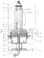
- the inverting filter centrifuge shown in the drawing comprises a schematically indicated housing 1 which tightly encloses the entire machine, in which a hollow shaft 3 is rotatably mounted in bearings 4, 5 on a stationary machine frame 2. With the end of the hollow shaft 3 protruding beyond the bearing 5, a drive wheel 6 is connected in a rotationally fixed manner, via which the hollow shaft 3 can be put into rapid rotation by an electric or other motor 7 by means of a V-belt.
- the hollow shaft 3 which is rigidly continuous between the bearings 4, 5 has an axially running keyway, indicated by dashed lines, in which a wedge piece 8 is axially displaceable.
- This wedge piece 8 is rigidly connected to a carrier shaft 9 which is displaceable inside the hollow shaft 3.
- the carrier shaft 9 therefore rotates together with the hollow shaft 3, but is axially displaceable in the latter.
- the closed bottom of a pot-shaped centrifugal drum 11 is flange-mounted on the end of the hollow shaft 3, which is on the left in FIGS. 1 and 2 and projects beyond the bearing 4.
- the drum 11 has radially extending through openings 12 on its cylindrical jacket.
- the drum 11 is open on its end face opposite the floor.
- On the flange-like opening edge 13 surrounding this open end face the edge of an essentially circular-cylindrical filter cloth 15 is tightly clamped by means of a retaining ring 14.
- the other edge of the filter cloth 15 is in a corresponding manner tightly connected to a base piece 16 which is rigidly connected to the displaceable, displaceable carrier shaft 9 which freely penetrates the bottom of the centrifugal drum 11.
- a centrifugal chamber cover 18 is rigidly attached to the base piece 16 by means of stud bolts 17, leaving a space free, which in FIG. 1 tightly closes the centrifugal space of the drum 11 by resting on its opening edge and in FIG. 2 together with the base part 16 by axially pushing out the carrier shaft 9 the hollow shaft 3 is lifted freely from the drum 11.
- a filling tube 19 is arranged on the front side of the inverting filter centrifuge, which is located on the left in FIGS serves ( Figure 1) and in the operating state shown in Figure 2 penetrates into a bore 21 of the slidable carrier shaft 9.
- the drive device which mediates the displacement of the carrier shaft 9 in the hollow shaft 3 and thus the opening and closing of the centrifugal drum and thus the transition between the two operating states shown in FIGS. 1 and 2 will be described in detail later.
- the inverting filter centrifuge initially assumes the position shown in FIG. 1.
- the displaceable carrier shaft 9 is retracted into the hollow shaft 3, as a result of which the bottom piece 16 connected to the carrier shaft 9 lies in the vicinity of the bottom of the centrifugal drum 11.
- the centrifugal chamber cover 16 has placed itself tightly on the opening edge of the drum 11.
- suspension to be filtered is introduced via the filling tube 19.
- the liquid constituents of the suspension pass through the openings 12 of the drum in the direction of the arrows 22 and are passed from a baffle plate 23 into a discharge line 24.
- the solid particles of the suspension are stopped by the filter cloth 15.
- the carrier shaft 9 With the centrifugal drum 11 still rotating, the carrier shaft 9 is now shifted (to the left) according to FIG. 2, as a result of which the filter cloth 15 is turned inside out and the solid particles adhering to it are thrown outwards in the direction of the arrows 25 into the housing 1. From there they can be easily removed.
- the filling tube 19 In the position according to FIG. 2, the filling tube 19 has penetrated into the bore 21 of the carrier shaft 9 through corresponding openings in the cover 18 and in the base piece 16.
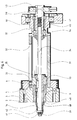
- a bushing 31 which has an axially extending slot 32, is flanged rigidly and non-rotatably to the end of the hollow shaft 3 supported by the bearing 5.
- a nut 33 With the rear end of the support shaft 9, a nut 33 is rigidly connected to a radially projecting wedge piece 30 which engages in the keyway 32, so that the wedge piece 30 provides a rotationally fixed connection between the nut 33 and the support shaft 9 on the one hand and the bushing 31 and the hollow shaft 3 on the other hand, however, the nut 33 and thus the carrier shaft 9 are axially displaceable in the bush 31.
- a screw spindle 34 which is provided with a corresponding external thread, engages in the internal thread of the nut 33 and is connected to a sleeve 36 in a rotationally fixed but axially displaceable manner via a conventional parallel key connection 35.
- the sleeve 36 is in turn rotatably supported by means of bearings 37, 38 in an end piece 45 fixedly flanged to the bushing 31.
- a washer 41 is held on the rear end of the screw spindle 34 projecting beyond the sleeve 36 by means of a nut 39.
- a plate spring 42 or the like is arranged, which the screw spindle 34 relative to the sleeve 36 (in 3 directed to the right), wherein the aforementioned key connection 35 between the screw spindle 34 and the sleeve 36 enables a slight axial movement between the screw spindle 34 and the sleeve 36.
- the plate spring 42 which prestresses the screw spindle 34 and thus also the carrier shaft 9 (to the right in FIG. 3) via the nut 33, has the purpose, in the working phase of centrifuging (FIG. 1), of the cover 18 against hydraulic pressure occurring inside the drum to hold fixed system at the opening edge of the centrifugal drum 11.
- the screw spindle 34 could also be rotatably mounted directly in the bearings 37 and 38, ie without the interposition of the sleeve 36. In this case, the pulley 43 would sit directly on the screw spindle 34 and the plate spring 42 used for the purpose mentioned would be omitted.
- the bush 31 is rotatably supported by means of the end piece 45 flanged to it in its own rotary bearing 46, which in turn is supported by a stand 47 on the machine frame 2, so that the drive forces exerted by the pulley 43 and the motor 44 in the vicinity of the bearing 46 can be collected.
- the relative speed of these parts, in particular the carrier shaft 9, and the screw spindle 34 and, above all, whether the screw spindle 34 is driven at a lower or greater speed than the carrier shaft 9 is important.
- carrier shaft 9 and screw spindle 34 there is no axial displacement of the carrier shaft 9 in the hollow shaft 3.
- the carrier shaft 9 and screw spindle 34 rotate simultaneously and in the same direction in the embodiment shown, and when an axial displacement of the carrier shaft 9 in the hollow shaft 3 is triggered, only the difference in speed between these parts 9 and 34 in a positive and negative sense is important, even with a relatively large one absolute speed of the screw spindle 34 causes only a relatively small axial stroke of the carrier shaft 9.
- the screw spindle 34 behaves like a screw with a very small pitch (fine thread), which in turn means that only small forces are required to drive it, and thus the motor 44 driving the screw spindle 34 can be made relatively weak, and indeed also when the carrier shaft 9 and screw spindle 34 are driven in opposite directions.
- the screw spindle closure arrangement described thus acts like a screw screw (provided with a fine thread) with self-locking, which does not require an additional radial locking.
- FIG. 3 shows the opening state of the centrifugal drum corresponding to FIG. 2, in which case the carrier shaft 9 is displaced completely to the left by the screw spindle 34 in FIG.
- the carrier shaft 9 has a cavity 48 in front of the nut 3 connected to it, into which the screw spindle 34 enters when the carrier shaft (to the right in FIG. 3) is retrieved during the closing movement of the centrifugal drum, the nut 33 in which a rearward extension of the hollow shaft 3 forming socket 31 moves accordingly.
- the screw spindle can be a spindle without self-locking, which can be achieved, for example, by a conventional ball screw.
- the locking force required for the safe locking of the centrifugal drum 11 is applied by the constantly switched on motor 44, which drives the screw spindle 34 at a lower speed than the electric motor 7, the hollow shaft 3 and thus the carrier shaft 9. It is also possible to to let the motor 44 or a corresponding section of the screw spindle 34 act on a separate, switchable brake. In particular, if the motor 44 is a frequency-controlled electric motor, this motor itself can serve as a brake.
- the motor 44 only initiates the opening movement of the centrifugal drum 11 when it drives the screw spindle 34 at a higher speed than the centrifugal chamber drum and with it revolve around the carrier shaft 9.
- the motor 44 is driven at a constant speed during the centrifuging work phase (FIG. 1), it causes the drum to be locked firmly as long as its speed is greater than the rotational speed of the screw spindle 34. Only when the speed of the centrifugal drum 11 drops below the speed of the screw spindle 34 during the transition to the working phase of solids discharge (FIG. 2) does the centrifugal drum open.
- FIG. 4 shows a further modified embodiment the invention.
- parts which correspond to one another are designated by the same reference symbols as in FIGS. 1 to 3.
- the screw spindle 34 is driven in rotation via the belt pulley 43 and the motor 44 in order to displace the carrier shaft 9 in the hollow shaft 3
- the screw spindle 34 is connected to the carrier shaft 9 in a rotationally fixed manner, and the sleeve 36 designed as a nut has an internal thread which engages with the external thread of the screw spindle 34.
- the sleeve 36 is axially immovable in the end piece 45 and is rotated via the pulley 43 and the motor 44, so that the screw 34 and with it the carrier shaft 9 are pushed axially back and forth, whereby the centrifugal chamber cover 18 is already in the opens or closes as described.
- the screw 34 is axially slidably mounted in a part 33 via a key 35, which in turn is fixedly connected to the carrier shaft 9.
- the screw spindle 34 is non-rotatably connected to the carrier shaft 9, but can move axially relative to the latter over a limited distance.
- the washer 41 is held by the nut 39, on which one end of the plate spring 42 is supported.
- the other end of the plate spring 42 lies in the cavity 48 of the carrier shaft 9 on an inner shoulder 49 or the like, so that the plate spring 42, just as in the embodiment according to FIG. 3, strives to pretension the carrier shaft 9 in such a way that in the working phase of centrifuging ( Figure 1) the centrifugal chamber cover 18 is held in fixed contact with the opening edge of the centrifugal drum 11.
- FIG. 4 represents a "kinematic reversal" to a certain extent compared to the embodiment according to FIG. In terms of their function and advantages, both versions correspond to each other.
- sleeve 36 which acts as a rotatingly driven nut in FIG. 4, could also be arranged between stationary machine frame 2 (see FIG. 1) and drum 11, if there the carrier shaft 9 emerging from the hollow shaft 3 is provided with a corresponding external thread which is in engagement with the sleeve acting as a nut.
- the sleeve could be driven via a pulley 43 and a correspondingly arranged motor 44.
Landscapes
- Centrifugal Separators (AREA)
Claims (10)
- Centrifugeuse à filtre retournable, comportant un tambour (11) monté à rotation dans un carter (1) et présentant des passages radiaux (12) de filtrat, un tissu filtrant retournable (15) recouvrant les passages de filtrat, avec un couvercle (18) fermant un des côtés frontaux du tambour, une ouverture de remplissage prévue sur le couvercle pour la suspension à filtrer, et un tube de remplissage (19) passant à travers cette ouverture de remplissage, le tambour et le couvercle pouvant, afin de retourner le filtre, être axialement déplacés l'un par rapport à l'autre au moyen d'un arbre creux (3) entraîné en rotation et d'un arbre porteur (9) mobile télescopiquement en va-et-vient dans cet arbre creux, caractérisée en ce qu'une broche filetée (34) est montée sur l'arbre porteur (9) et il est prévu un écrou (33, 36) en prise avec cette broche filetée, et en ce que soit la broche filetée (34), soit l'écrou (36) peut être entraîné(e) en rotation par un moteur (44), de sorte que l'arbre porteur (9) se déplace télescopiquement en va-et-vient dans l'arbre creux (3) en fonction du régime de la broche filetée (34) ou de l'écrou (36) par rapport au régime de l'arbre creux (3).
- Centrifugeuse à filtre retournable selon la revendication 1, caractérisée en ce que l'écrou (33) est monté fixe à l'extrémité arrière de l'arbre porteur (9), opposée au tambour (11), et la broche filetée (34) s'engage dans l'écrou, en ce que la broche filetée (34) est montée à rotation dans un prolongement arrière (manchon 31), dirigé en éloignement du tambour (11), de l'arbre creux (3), et en ce que la broche filetée (34) peut être entraînée en rotation au moyen du moteur (44).
- Centrifugeuse à filtre retournable selon la revendication 1, caractérisée en ce que la broche filetée (34) est reliée solidairement en rotation à l'arbre porteur (9), et un écrou (36) rotatif et bloqué en translation axiale, qui peut être entraîné en rotation au moyen du moteur (44), est en prise avec le filetage extérieur de la broche filetée.
- Centrifugeuse à filtre retournable selon la revendication 2, caractérisée en ce que l'arbre porteur (9) présente, entre le tambour (11) et l'écrou (33), un espace creux (48) dans lequel pénètre une extrémité libre de la broche filetée (34) lors d'un déplacement correspondant de l'arbre porteur (9) par rapport à l'arbre creux (3).
- Centrifugeuse à filtre retournable selon la revendication 1, caractérisée en ce qu'il est prévu, sur un prolongement arrière (manchon 31) de l'arbre creux (3), un évidement (32) parallèle à l'axe de ce prolongement et dans lequel s'engage, pour le blocage en rotation, une clavette (30) fixement assemblée à l'arbre porteur (9).
- Centrifugeuse à filtre retournable selon les revendications 2 et 5, caractérisée en ce que la clavette (30) est disposée sur l'écrou (33).
- Centrifugeuse à filtre retournable selon la revendication 5, caractérisée en ce que le prolongement arrière (manchon 31) de l'arbre creux (3) est soutenu dans au moins un palier de rotation (46, 47).
- Centrifugeuse à filtre retournable selon les revendications 2 et 5, caractérisée en ce que la broche filetée (34) est disposée en solidarité de rotation, et avec possibilité de translation, dans une douille (36) montée tournante dans le prolongement arrière (manchon 31) de l'arbre creux (3), et cette douille (36) peut être entraînée au moyen du moteur (44).
- Centrifugeuse à filtre retournable selon la revendication 8, caractérisée en ce que la broche filetée (34) dépasse librement de la douille (36) à son extrémité arrière opposée à l'arbre porteur (9), et un ressort (42) est disposé entre cette extrémité arrière de la douille (36) et l'extrémité libre de la broche filetée (34), lequel ressort précontraint la broche filetée (34) et donc l'arbre porteur (9) en direction de la douille (36).
- Centrifugeuse à filtre retournable selon la revendication 1, caractérisée en ce que la broche filetée (34) peut être entraînée par le moteur (44) par l'intermédiaire d'une poulie de courroie (43).
Priority Applications (12)
| Application Number | Priority Date | Filing Date | Title |
|---|---|---|---|
| EP90105623A EP0448736B1 (fr) | 1990-03-24 | 1990-03-24 | Centrifugeuse à filtre réversible |
| DE59008312T DE59008312D1 (de) | 1990-03-24 | 1990-03-24 | Stülpfilterzentrifuge. |
| ES90105623T ES2066893T3 (es) | 1990-03-24 | 1990-03-24 | Centrifuga de filtro invertible. |
| AT90105623T ATE117221T1 (de) | 1990-03-24 | 1990-03-24 | Stülpfilterzentrifuge. |
| DK90105623.4T DK0448736T3 (da) | 1990-03-24 | 1990-03-24 | Vendefiltercentrifuge |
| US07/848,946 US5277804A (en) | 1990-03-24 | 1991-01-15 | Sleeve filter centrifuge |
| KR1019920702232A KR0163357B1 (ko) | 1990-03-24 | 1991-01-15 | 슬리이브 필터 원심분리기 |
| SU915053018A RU2067893C1 (ru) | 1990-03-24 | 1991-01-15 | Фильтрующая центрифуга с выворачиваемым фильтром |
| JP50368191A JP3315979B2 (ja) | 1990-03-24 | 1991-01-15 | フィルタ反転式遠心分離器 |
| PCT/EP1991/000045 WO1991014506A1 (fr) | 1990-03-24 | 1991-01-15 | Centrifugeuse avec filtre manchon |
| CN91101702.XA CN1025009C (zh) | 1990-03-24 | 1991-03-20 | 翻口过滤器式离心机 |
| GR950400615T GR3015484T3 (en) | 1990-03-24 | 1995-03-20 | Reversible filter centrifuge. |
Applications Claiming Priority (1)
| Application Number | Priority Date | Filing Date | Title |
|---|---|---|---|
| EP90105623A EP0448736B1 (fr) | 1990-03-24 | 1990-03-24 | Centrifugeuse à filtre réversible |
Publications (2)
| Publication Number | Publication Date |
|---|---|
| EP0448736A1 EP0448736A1 (fr) | 1991-10-02 |
| EP0448736B1 true EP0448736B1 (fr) | 1995-01-18 |
Family
ID=8203807
Family Applications (1)
| Application Number | Title | Priority Date | Filing Date |
|---|---|---|---|
| EP90105623A Expired - Lifetime EP0448736B1 (fr) | 1990-03-24 | 1990-03-24 | Centrifugeuse à filtre réversible |
Country Status (11)
| Country | Link |
|---|---|
| EP (1) | EP0448736B1 (fr) |
| JP (1) | JP3315979B2 (fr) |
| KR (1) | KR0163357B1 (fr) |
| CN (1) | CN1025009C (fr) |
| AT (1) | ATE117221T1 (fr) |
| DE (1) | DE59008312D1 (fr) |
| DK (1) | DK0448736T3 (fr) |
| ES (1) | ES2066893T3 (fr) |
| GR (1) | GR3015484T3 (fr) |
| RU (1) | RU2067893C1 (fr) |
| WO (1) | WO1991014506A1 (fr) |
Families Citing this family (5)
| Publication number | Priority date | Publication date | Assignee | Title |
|---|---|---|---|---|
| DE4337620C1 (de) * | 1993-11-04 | 1995-03-09 | Krauss Maffei Ag | Stülpfilterzentrifuge (Trommeldeckel-Verriegelung) |
| CN100434186C (zh) * | 2006-10-16 | 2008-11-19 | 张鹤鸣 | 翻袋式过滤离心机 |
| CN102357433A (zh) * | 2011-09-08 | 2012-02-22 | 安徽普源分离机械制造有限公司 | 卧式全自动拉袋离心机 |
| JP6618433B2 (ja) * | 2016-07-05 | 2019-12-11 | 月島機械株式会社 | 遠心分離装置および遠心分離方法 |
| CN117000448B (zh) * | 2023-07-18 | 2026-03-31 | 江苏同泽过滤科技有限公司 | 一种过滤离心机中的过滤装置 |
Family Cites Families (3)
| Publication number | Priority date | Publication date | Assignee | Title |
|---|---|---|---|---|
| DE458908C (de) * | 1926-05-12 | 1928-04-23 | Ver Ijzerfabrieken De Vijf Nv | Spinntopfantrieb |
| DE2709894C3 (de) * | 1977-03-08 | 1982-01-07 | Heinkel Industriezentrifugen GmbH & Co, 7120 Bietigheim-Bissingen | Diskontinuierliche Filterzentrifuge |
| SU1118414A1 (ru) * | 1982-07-26 | 1984-10-15 | Всесоюзный Научно-Исследовательский И Проектный Институт Мономеров | Центрифуга |
-
1990
- 1990-03-24 DE DE59008312T patent/DE59008312D1/de not_active Expired - Fee Related
- 1990-03-24 ES ES90105623T patent/ES2066893T3/es not_active Expired - Lifetime
- 1990-03-24 EP EP90105623A patent/EP0448736B1/fr not_active Expired - Lifetime
- 1990-03-24 AT AT90105623T patent/ATE117221T1/de not_active IP Right Cessation
- 1990-03-24 DK DK90105623.4T patent/DK0448736T3/da active
-
1991
- 1991-01-15 JP JP50368191A patent/JP3315979B2/ja not_active Expired - Fee Related
- 1991-01-15 WO PCT/EP1991/000045 patent/WO1991014506A1/fr not_active Ceased
- 1991-01-15 RU SU915053018A patent/RU2067893C1/ru not_active IP Right Cessation
- 1991-01-15 KR KR1019920702232A patent/KR0163357B1/ko not_active Expired - Fee Related
- 1991-03-20 CN CN91101702.XA patent/CN1025009C/zh not_active Expired - Fee Related
-
1995
- 1995-03-20 GR GR950400615T patent/GR3015484T3/el unknown
Also Published As
| Publication number | Publication date |
|---|---|
| CN1055129A (zh) | 1991-10-09 |
| JPH05505339A (ja) | 1993-08-12 |
| EP0448736A1 (fr) | 1991-10-02 |
| WO1991014506A1 (fr) | 1991-10-03 |
| RU2067893C1 (ru) | 1996-10-20 |
| KR930700209A (ko) | 1993-03-13 |
| KR0163357B1 (ko) | 1998-11-16 |
| GR3015484T3 (en) | 1995-06-30 |
| JP3315979B2 (ja) | 2002-08-19 |
| ES2066893T3 (es) | 1995-03-16 |
| ATE117221T1 (de) | 1995-02-15 |
| CN1025009C (zh) | 1994-06-15 |
| DK0448736T3 (da) | 1995-04-03 |
| DE59008312D1 (de) | 1995-03-02 |
Similar Documents
| Publication | Publication Date | Title |
|---|---|---|
| EP0027630B1 (fr) | Centrifugeuse pour la séparation de mélanges solide-liquide | |
| EP0472554B2 (fr) | Centrifugeuse a filtre retourne | |
| EP3268122B1 (fr) | Centrifugeuse avec rotors remplaceables | |
| EP0253181A2 (fr) | Mécanisme de fixation d'outils en forme de disque sur une broche de machine-outil électrique portative | |
| DE69405051T2 (de) | Decantierzentrifuge zur Behandlung von nuklearen Produkten | |
| EP0448737B1 (fr) | Centrifugeuse à filtre réversible | |
| EP0551252B1 (fr) | Centrifugeuse a filtre retourne | |
| DE1782260A1 (de) | Zentrifuge | |
| EP0448736B1 (fr) | Centrifugeuse à filtre réversible | |
| DE102011002126A1 (de) | Zentrifuge und Verfahren zur Überwachung eines Drehmoments | |
| EP0652051A1 (fr) | Dispositif d'étanchéité pour tambour d'une centrifugeuse à filtre réversible | |
| DE4342471C1 (de) | Filterzentrifuge | |
| EP0642834A2 (fr) | Dispositif de verrouillage pour agencement de paliers en particulier pour la chambre de séparation d'une centrifugeuse | |
| DE3520134C2 (de) | Stülpfilter-Zentrifuge | |
| EP0654620B1 (fr) | Dispositif d'entraînement de groupes auxiliaires | |
| DE19500046C1 (de) | Mechanische Kupplung | |
| EP1163976A1 (fr) | Entrainement avec une transmission variable pour un dispositif porte outil | |
| DE69127946T2 (de) | Partikelkonzentrator | |
| DE29823115U1 (de) | Linearantrieb | |
| EP1277899B1 (fr) | Dispositif d'actionnement pour serrure de porte de véhicule | |
| DE102014106462B3 (de) | Schwenkgetriebe sowie Schwenkantriebssystem mit einem solchen und Schälzentrifuge und Filteranlage mit einem solchen Schwenkantriebssystem | |
| WO1991008399A1 (fr) | Dispositif d'actionnement hydraulique pour accouplement a friction | |
| DE102005002858B4 (de) | Getriebeanordnung einer Antriebsachse eines Kraftfahrzeuges | |
| DE2305326B2 (de) | Siebzentrifuge, insbesondere Zukkerzentrifuge | |
| DE2363170C3 (de) | Hydraulische Einspritzeinheit einer Kunststoff-Spritzgießmaschine |
Legal Events
| Date | Code | Title | Description |
|---|---|---|---|
| PUAI | Public reference made under article 153(3) epc to a published international application that has entered the european phase |
Free format text: ORIGINAL CODE: 0009012 |
|
| 17P | Request for examination filed |
Effective date: 19910112 |
|
| AK | Designated contracting states |
Kind code of ref document: A1 Designated state(s): AT BE CH DE DK ES FR GB GR IT LI LU NL SE |
|
| 17Q | First examination report despatched |
Effective date: 19921201 |
|
| GRAA | (expected) grant |
Free format text: ORIGINAL CODE: 0009210 |
|
| ITF | It: translation for a ep patent filed | ||
| AK | Designated contracting states |
Kind code of ref document: B1 Designated state(s): AT BE CH DE DK ES FR GB GR IT LI LU NL SE |
|
| REF | Corresponds to: |
Ref document number: 117221 Country of ref document: AT Date of ref document: 19950215 Kind code of ref document: T |
|
| REF | Corresponds to: |
Ref document number: 59008312 Country of ref document: DE Date of ref document: 19950302 |
|
| GBT | Gb: translation of ep patent filed (gb section 77(6)(a)/1977) |
Effective date: 19950214 |
|
| REG | Reference to a national code |
Ref country code: ES Ref legal event code: FG2A Ref document number: 2066893 Country of ref document: ES Kind code of ref document: T3 |
|
| PG25 | Lapsed in a contracting state [announced via postgrant information from national office to epo] |
Ref country code: LU Free format text: LAPSE BECAUSE OF NON-PAYMENT OF DUE FEES Effective date: 19950331 |
|
| REG | Reference to a national code |
Ref country code: DK Ref legal event code: T3 |
|
| ET | Fr: translation filed | ||
| REG | Reference to a national code |
Ref country code: GR Ref legal event code: FG4A Free format text: 3015484 |
|
| PLBE | No opposition filed within time limit |
Free format text: ORIGINAL CODE: 0009261 |
|
| STAA | Information on the status of an ep patent application or granted ep patent |
Free format text: STATUS: NO OPPOSITION FILED WITHIN TIME LIMIT |
|
| 26N | No opposition filed | ||
| REG | Reference to a national code |
Ref country code: GB Ref legal event code: IF02 |
|
| PGFP | Annual fee paid to national office [announced via postgrant information from national office to epo] |
Ref country code: GR Payment date: 20031224 Year of fee payment: 15 |
|
| PGFP | Annual fee paid to national office [announced via postgrant information from national office to epo] |
Ref country code: SE Payment date: 20031230 Year of fee payment: 15 |
|
| PGFP | Annual fee paid to national office [announced via postgrant information from national office to epo] |
Ref country code: BE Payment date: 20040115 Year of fee payment: 15 |
|
| PGFP | Annual fee paid to national office [announced via postgrant information from national office to epo] |
Ref country code: DK Payment date: 20040123 Year of fee payment: 15 |
|
| PGFP | Annual fee paid to national office [announced via postgrant information from national office to epo] |
Ref country code: AT Payment date: 20040303 Year of fee payment: 15 |
|
| PGFP | Annual fee paid to national office [announced via postgrant information from national office to epo] |
Ref country code: ES Payment date: 20040309 Year of fee payment: 15 |
|
| PGFP | Annual fee paid to national office [announced via postgrant information from national office to epo] |
Ref country code: FR Payment date: 20040317 Year of fee payment: 15 |
|
| PGFP | Annual fee paid to national office [announced via postgrant information from national office to epo] |
Ref country code: GB Payment date: 20040323 Year of fee payment: 15 |
|
| PGFP | Annual fee paid to national office [announced via postgrant information from national office to epo] |
Ref country code: NL Payment date: 20040331 Year of fee payment: 15 |
|
| PG25 | Lapsed in a contracting state [announced via postgrant information from national office to epo] |
Ref country code: GB Free format text: LAPSE BECAUSE OF NON-PAYMENT OF DUE FEES Effective date: 20050324 Ref country code: AT Free format text: LAPSE BECAUSE OF NON-PAYMENT OF DUE FEES Effective date: 20050324 |
|
| PG25 | Lapsed in a contracting state [announced via postgrant information from national office to epo] |
Ref country code: SE Free format text: LAPSE BECAUSE OF NON-PAYMENT OF DUE FEES Effective date: 20050325 |
|
| PG25 | Lapsed in a contracting state [announced via postgrant information from national office to epo] |
Ref country code: ES Free format text: LAPSE BECAUSE OF NON-PAYMENT OF DUE FEES Effective date: 20050326 |
|
| PG25 | Lapsed in a contracting state [announced via postgrant information from national office to epo] |
Ref country code: DK Free format text: LAPSE BECAUSE OF NON-PAYMENT OF DUE FEES Effective date: 20050331 Ref country code: BE Free format text: LAPSE BECAUSE OF NON-PAYMENT OF DUE FEES Effective date: 20050331 |
|
| BERE | Be: lapsed |
Owner name: *HEINKEL INDUSTRIEZENTRIFUGEN G.M.B.H. & CO. Effective date: 20050331 |
|
| PG25 | Lapsed in a contracting state [announced via postgrant information from national office to epo] |
Ref country code: NL Free format text: LAPSE BECAUSE OF NON-PAYMENT OF DUE FEES Effective date: 20051001 |
|
| PG25 | Lapsed in a contracting state [announced via postgrant information from national office to epo] |
Ref country code: GR Free format text: LAPSE BECAUSE OF NON-PAYMENT OF DUE FEES Effective date: 20051004 |
|
| EUG | Se: european patent has lapsed | ||
| GBPC | Gb: european patent ceased through non-payment of renewal fee |
Effective date: 20050324 |
|
| PG25 | Lapsed in a contracting state [announced via postgrant information from national office to epo] |
Ref country code: FR Free format text: LAPSE BECAUSE OF NON-PAYMENT OF DUE FEES Effective date: 20051130 |
|
| NLV4 | Nl: lapsed or anulled due to non-payment of the annual fee |
Effective date: 20051001 |
|
| REG | Reference to a national code |
Ref country code: DK Ref legal event code: EBP |
|
| REG | Reference to a national code |
Ref country code: FR Ref legal event code: ST Effective date: 20051130 |
|
| REG | Reference to a national code |
Ref country code: ES Ref legal event code: FD2A Effective date: 20050326 |
|
| REG | Reference to a national code |
Ref country code: CH Ref legal event code: PCAR Free format text: ISLER & PEDRAZZINI AG;POSTFACH 1772;8027 ZUERICH (CH) |
|
| BERE | Be: lapsed |
Owner name: *HEINKEL INDUSTRIEZENTRIFUGEN G.M.B.H. & CO. Effective date: 20050331 |
|
| PGFP | Annual fee paid to national office [announced via postgrant information from national office to epo] |
Ref country code: IT Payment date: 20080208 Year of fee payment: 19 |
|
| PGFP | Annual fee paid to national office [announced via postgrant information from national office to epo] |
Ref country code: DE Payment date: 20080425 Year of fee payment: 19 Ref country code: CH Payment date: 20080409 Year of fee payment: 19 |
|
| REG | Reference to a national code |
Ref country code: CH Ref legal event code: PL |
|
| PG25 | Lapsed in a contracting state [announced via postgrant information from national office to epo] |
Ref country code: DE Free format text: LAPSE BECAUSE OF NON-PAYMENT OF DUE FEES Effective date: 20091001 Ref country code: CH Free format text: LAPSE BECAUSE OF NON-PAYMENT OF DUE FEES Effective date: 20090331 Ref country code: LI Free format text: LAPSE BECAUSE OF NON-PAYMENT OF DUE FEES Effective date: 20090331 |
|
| PG25 | Lapsed in a contracting state [announced via postgrant information from national office to epo] |
Ref country code: IT Free format text: LAPSE BECAUSE OF NON-PAYMENT OF DUE FEES Effective date: 20090324 |