EP0448277A1 - Dispositif pour un test de sécurité - Google Patents
Dispositif pour un test de sécurité Download PDFInfo
- Publication number
- EP0448277A1 EP0448277A1 EP91302096A EP91302096A EP0448277A1 EP 0448277 A1 EP0448277 A1 EP 0448277A1 EP 91302096 A EP91302096 A EP 91302096A EP 91302096 A EP91302096 A EP 91302096A EP 0448277 A1 EP0448277 A1 EP 0448277A1
- Authority
- EP
- European Patent Office
- Prior art keywords
- joint
- test device
- push
- components
- pull
- Prior art date
- Legal status (The legal status is an assumption and is not a legal conclusion. Google has not performed a legal analysis and makes no representation as to the accuracy of the status listed.)
- Granted
Links
- 238000012360 testing method Methods 0.000 title claims abstract description 37
- 238000010998 test method Methods 0.000 claims description 3
- 208000032767 Device breakage Diseases 0.000 claims description 2
- 238000000034 method Methods 0.000 claims description 2
- 238000011179 visual inspection Methods 0.000 description 4
- 238000013100 final test Methods 0.000 description 1
- 239000012530 fluid Substances 0.000 description 1
- 238000003780 insertion Methods 0.000 description 1
- 230000037431 insertion Effects 0.000 description 1
- 238000007689 inspection Methods 0.000 description 1
- 238000010422 painting Methods 0.000 description 1
- 238000007789 sealing Methods 0.000 description 1
Images
Classifications
-
- F—MECHANICAL ENGINEERING; LIGHTING; HEATING; WEAPONS; BLASTING
- F16—ENGINEERING ELEMENTS AND UNITS; GENERAL MEASURES FOR PRODUCING AND MAINTAINING EFFECTIVE FUNCTIONING OF MACHINES OR INSTALLATIONS; THERMAL INSULATION IN GENERAL
- F16B—DEVICES FOR FASTENING OR SECURING CONSTRUCTIONAL ELEMENTS OR MACHINE PARTS TOGETHER, e.g. NAILS, BOLTS, CIRCLIPS, CLAMPS, CLIPS OR WEDGES; JOINTS OR JOINTING
- F16B21/00—Means for preventing relative axial movement of a pin, spigot, shaft or the like and a member surrounding it; Stud-and-socket releasable fastenings
- F16B21/06—Releasable fastening devices with snap-action
-
- F—MECHANICAL ENGINEERING; LIGHTING; HEATING; WEAPONS; BLASTING
- F16—ENGINEERING ELEMENTS AND UNITS; GENERAL MEASURES FOR PRODUCING AND MAINTAINING EFFECTIVE FUNCTIONING OF MACHINES OR INSTALLATIONS; THERMAL INSULATION IN GENERAL
- F16B—DEVICES FOR FASTENING OR SECURING CONSTRUCTIONAL ELEMENTS OR MACHINE PARTS TOGETHER, e.g. NAILS, BOLTS, CIRCLIPS, CLAMPS, CLIPS OR WEDGES; JOINTS OR JOINTING
- F16B7/00—Connections of rods or tubes, e.g. of non-circular section, mutually, including resilient connections
- F16B7/04—Clamping or clipping connections
-
- F—MECHANICAL ENGINEERING; LIGHTING; HEATING; WEAPONS; BLASTING
- F16—ENGINEERING ELEMENTS AND UNITS; GENERAL MEASURES FOR PRODUCING AND MAINTAINING EFFECTIVE FUNCTIONING OF MACHINES OR INSTALLATIONS; THERMAL INSULATION IN GENERAL
- F16L—PIPES; JOINTS OR FITTINGS FOR PIPES; SUPPORTS FOR PIPES, CABLES OR PROTECTIVE TUBING; MEANS FOR THERMAL INSULATION IN GENERAL
- F16L37/00—Couplings of the quick-acting type
- F16L37/08—Couplings of the quick-acting type in which the connection between abutting or axially overlapping ends is maintained by locking members
- F16L37/084—Couplings of the quick-acting type in which the connection between abutting or axially overlapping ends is maintained by locking members combined with automatic locking
- F16L37/098—Couplings of the quick-acting type in which the connection between abutting or axially overlapping ends is maintained by locking members combined with automatic locking by means of flexible hooks
-
- G—PHYSICS
- G01—MEASURING; TESTING
- G01L—MEASURING FORCE, STRESS, TORQUE, WORK, MECHANICAL POWER, MECHANICAL EFFICIENCY, OR FLUID PRESSURE
- G01L5/00—Apparatus for, or methods of, measuring force, work, mechanical power, or torque, specially adapted for specific purposes
- G01L5/0028—Force sensors associated with force applying means
- G01L5/0033—Force sensors associated with force applying means applying a pulling force
-
- F—MECHANICAL ENGINEERING; LIGHTING; HEATING; WEAPONS; BLASTING
- F16—ENGINEERING ELEMENTS AND UNITS; GENERAL MEASURES FOR PRODUCING AND MAINTAINING EFFECTIVE FUNCTIONING OF MACHINES OR INSTALLATIONS; THERMAL INSULATION IN GENERAL
- F16L—PIPES; JOINTS OR FITTINGS FOR PIPES; SUPPORTS FOR PIPES, CABLES OR PROTECTIVE TUBING; MEANS FOR THERMAL INSULATION IN GENERAL
- F16L2201/00—Special arrangements for pipe couplings
- F16L2201/10—Indicators for correct coupling
Definitions
- This invention relates to a security test device for checking the condition of a push-fit assembly.
- a test device for a push-in joint between two components comprising a first part to be fixed to one of the components, a second part which can be gripped to exert a pull force in a direction opposite to the push-in direction, and a rupturable region which will break when a predetermined pull force is applied to the second part so that the second part becomes detached from the joint.
- the rupturable region may be formed between the first and second parts, so that when the region breaks the first part remains fixed to said one of the components.
- the first part itself may rupture so that the entire device becomes detached from the joint when the rupturable region breaks.
- the second part is preferably brightly coloured or made easily visible in some way so that it is easy to carry out a visual inspection to see whether the assembly test has been performed.
- the second part is in the form of a ring into which an assembly worker can place his or her finger in order to exert a pull force.
- the first part of the device may be a ring which engages behind a shoulder on the component so that the test device can be attached to the component merely by slipping it over one end of the component.
- a test device having a predetermined rupture point is fixed to one of the components, the joint is assembled and a pull-out force is applied to the joint by pulling the test device until the device ruptures, the predetermined rupture point being set such that the pull-out force applied would be sufficient to disassemble an incorrectly assembled joint but not sufficient to cause damage to a correctly assembled joint.
- the push-in joint may be part of a fluid flow system in which one tube is coupled to another to form a sealed joint. To ensure a proper seal, it is important that the joint is assembled as designed, and the invention allows this to be done effectively.
- the push-in joint may be part of an electrical connection where one electrical contact or set of contacts is pushed into another contact or set of contacts. Again, it is important that the connection be assembled as designed and the invention allows this to be done effectively.
- the test device may have the features set forth above.
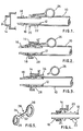
- a flexible tube 10 is fitted at its free end with an end fitting 12.
- the end fitting consists of a tubular body with spring legs 16 at its outer end, an O-ring seal 18, a shoulder 20 and annular ridges 22 for retaining the tube 10.
- the end fitting 12 is intended for insertion into a bore 24 in a separate component 14.
- the spring legs 16 which are compressed inwardly during passage through the bore spring out to lock the fitting in the component 14, and the O-ring seal 18 then makes sealing contact with the walls of the bore 24. This is the correctly assembled condition.
- a test device 26 is assembled onto the end fitting 12 and is located between the shoulder 20 and the end of the tube 10.
- the test device is fitted in this position by placing a first part which ends in a ring 28 (see figure 5) over the end fitting 12 before the tube 10 is put in place.
- the test device then has an exposed ring 30 through which a finger can be inserted, and a limb 32 joining the two rings 28 and 30.
- the limb 32 is constructed so that it can snap at a predetermined load, and in figure 5 the rupturable region, or snap zone is indicated at 34.
- Figure 4 illustrates a misassembled condition of the joint, where the end fitting 12 has not been pushed fully in and the spring legs 16 have not opened out again on the far side of the bore 24. If the ring 30 is pulled with the joint in this condition, then the end fitting 12 will pull out of the component 14. The joint can then be remade properly.
- the ring part 30 of the test device is preferably brightly coloured, for example by painting it yellow so that its presence or absence will be readily apparent from a visual inspection.
- the position of the snap region 34 will be chosen so that the broken end of the limb 32 which remains on the joint remains concealed so far as possible.
- the snap region 34 does not have to be between the two rings 28 and 30. There may be a weakened portion around the circumference of the ring 28, so that when rupturing occurs the whole of the ring is pulled away from the joint.
- test device described thus provides a cheap, simple and easily verifiable system for checking the joints have been correctly assembled and for checking that the checking has been carried out.
Applications Claiming Priority (2)
| Application Number | Priority Date | Filing Date | Title |
|---|---|---|---|
| GB9006285 | 1990-03-21 | ||
| GB9006285A GB2242281A (en) | 1990-03-21 | 1990-03-21 | Security test device |
Publications (2)
| Publication Number | Publication Date |
|---|---|
| EP0448277A1 true EP0448277A1 (fr) | 1991-09-25 |
| EP0448277B1 EP0448277B1 (fr) | 1994-05-25 |
Family
ID=10672951
Family Applications (1)
| Application Number | Title | Priority Date | Filing Date |
|---|---|---|---|
| EP91302096A Expired - Lifetime EP0448277B1 (fr) | 1990-03-21 | 1991-03-13 | Dispositif pour un test de sécurité |
Country Status (4)
| Country | Link |
|---|---|
| US (1) | US5257548A (fr) |
| EP (1) | EP0448277B1 (fr) |
| DE (1) | DE69102090T2 (fr) |
| GB (1) | GB2242281A (fr) |
Cited By (2)
| Publication number | Priority date | Publication date | Assignee | Title |
|---|---|---|---|---|
| FR2705133A1 (fr) * | 1993-05-10 | 1994-11-18 | Caillau Ets | Connexion rapide. |
| DE102010040519A1 (de) * | 2010-09-09 | 2012-03-15 | Adolf Würth GmbH & Co. KG | Testen der Festigkeit einer Verbindung zwischen einem Untergrund und einem darin eingesetzten Befestigungselement mittels eines Opferelements |
Families Citing this family (6)
| Publication number | Priority date | Publication date | Assignee | Title |
|---|---|---|---|---|
| US5297818A (en) * | 1991-12-18 | 1994-03-29 | Itt Corporation | Retainer for pop-top indicator |
| US5499848A (en) * | 1994-09-26 | 1996-03-19 | Bundy Corporation | Connection verifier for a quick connector coupling |
| US5653147A (en) * | 1995-08-10 | 1997-08-05 | Teleflex Incorporated | Expandable retainer for conduit end fitting |
| US5613405A (en) * | 1995-11-13 | 1997-03-25 | Teleflex Incorporated | Cable assembly with telescoping core terminal |
| AU4745197A (en) | 1996-10-09 | 1998-05-05 | Dura Automotive Systems, Inc. | Expanding lock control cable end fitting |
| US6810569B1 (en) | 2003-07-08 | 2004-11-02 | Visteon Global Technologies, Inc. | Workpiece release with computer verified connections |
Citations (4)
| Publication number | Priority date | Publication date | Assignee | Title |
|---|---|---|---|---|
| DE1996317U (de) * | 1968-08-07 | 1968-11-07 | Daimler Benz Ag | Unterlagscheibe fuer schraubverbindungen. |
| DE2755428A1 (de) * | 1977-12-13 | 1979-06-21 | Becker Pruente Gmbh | Auswechselbare ueberlastungskontrolle fuer lastketten |
| EP0186358A2 (fr) * | 1984-12-10 | 1986-07-02 | Illinois Tool Works Inc. | Dispositif pour la mesure de résistance de tirage |
| US4775273A (en) * | 1981-01-23 | 1988-10-04 | Peter Bauer | Bistable shaft retaining element |
Family Cites Families (8)
| Publication number | Priority date | Publication date | Assignee | Title |
|---|---|---|---|---|
| US3762059A (en) * | 1971-06-21 | 1973-10-02 | Mc Donnell Douglas Corp | Check gauge for swaged fitting and tube connections |
| US4979765A (en) * | 1980-10-29 | 1990-12-25 | Proprietary Technology, Inc. | Swivelable quick connector assembly |
| DE3535226A1 (de) * | 1985-10-02 | 1987-04-16 | Schmalbach Lubeca | Deckel aus blech fuer unrunde dosen, insb. langovale dosen im hansa-format |
| US4687114A (en) * | 1986-01-21 | 1987-08-18 | Northern Engineering And Plastics Corp. | Tamper indicating closure for containers |
| US4667837A (en) * | 1986-06-05 | 1987-05-26 | International Medical Industries, Incorporated | Tamper proof cap |
| US4753458A (en) * | 1986-08-28 | 1988-06-28 | Harvard Industries, Inc. | Quick connector assembly |
| US4948176A (en) * | 1987-09-14 | 1990-08-14 | Proprietary Technology, Inc. | Swivelable quick connector assembly |
| JP2691550B2 (ja) * | 1988-03-01 | 1997-12-17 | 臼井国際産業株式会社 | 細径配管接続用コネクター |
-
1990
- 1990-03-21 GB GB9006285A patent/GB2242281A/en not_active Withdrawn
-
1991
- 1991-03-13 EP EP91302096A patent/EP0448277B1/fr not_active Expired - Lifetime
- 1991-03-13 DE DE69102090T patent/DE69102090T2/de not_active Expired - Fee Related
- 1991-03-20 US US07/672,281 patent/US5257548A/en not_active Expired - Fee Related
Patent Citations (4)
| Publication number | Priority date | Publication date | Assignee | Title |
|---|---|---|---|---|
| DE1996317U (de) * | 1968-08-07 | 1968-11-07 | Daimler Benz Ag | Unterlagscheibe fuer schraubverbindungen. |
| DE2755428A1 (de) * | 1977-12-13 | 1979-06-21 | Becker Pruente Gmbh | Auswechselbare ueberlastungskontrolle fuer lastketten |
| US4775273A (en) * | 1981-01-23 | 1988-10-04 | Peter Bauer | Bistable shaft retaining element |
| EP0186358A2 (fr) * | 1984-12-10 | 1986-07-02 | Illinois Tool Works Inc. | Dispositif pour la mesure de résistance de tirage |
Cited By (5)
| Publication number | Priority date | Publication date | Assignee | Title |
|---|---|---|---|---|
| FR2705133A1 (fr) * | 1993-05-10 | 1994-11-18 | Caillau Ets | Connexion rapide. |
| EP0627592A1 (fr) * | 1993-05-10 | 1994-12-07 | Etablissements CAILLAU | Connexion rapide |
| US5431454A (en) * | 1993-05-10 | 1995-07-11 | Etablissements Caillau | Quick connection |
| DE102010040519A1 (de) * | 2010-09-09 | 2012-03-15 | Adolf Würth GmbH & Co. KG | Testen der Festigkeit einer Verbindung zwischen einem Untergrund und einem darin eingesetzten Befestigungselement mittels eines Opferelements |
| DE102010040519B4 (de) * | 2010-09-09 | 2016-09-01 | Adolf Würth GmbH & Co. KG | Testen der Festigkeit einer Verbindung zwischen einem Untergrund und einem darin eingesetzten Befestigungselement mittels eines Opferelements |
Also Published As
| Publication number | Publication date |
|---|---|
| US5257548A (en) | 1993-11-02 |
| GB2242281A (en) | 1991-09-25 |
| DE69102090D1 (de) | 1994-06-30 |
| GB9006285D0 (en) | 1990-05-16 |
| DE69102090T2 (de) | 1994-09-01 |
| EP0448277B1 (fr) | 1994-05-25 |
Similar Documents
| Publication | Publication Date | Title |
|---|---|---|
| US5441313A (en) | Insertion indicator for quick connector | |
| EP0703398B1 (fr) | Dispositif de vérification de la connexion d'un raccord rapide | |
| US6082779A (en) | Releasable plug connector with mounting display | |
| US5518276A (en) | Quick connector with pull back verification method | |
| JP2837663B2 (ja) | 迅速コネクタ継合表示具と迅速コネクタ組体 | |
| JP2588417B2 (ja) | 配管接続用コネクタ | |
| US4170939A (en) | Ignition device for a passive retention system | |
| US5485982A (en) | Quick connector with tube activated check valve | |
| US5342099A (en) | Fluid coupling with condition indicator | |
| US4655486A (en) | Water faucet inlet line connector | |
| EP0448277B1 (fr) | Dispositif pour un test de sécurité | |
| EP0525414A1 (fr) | Dispositif indicateur pour raccord rapide | |
| US5785358A (en) | Connection verifier for a quick connector coupling | |
| JPS63115986A (ja) | 急速継手 | |
| BRPI0417484B1 (pt) | acoplamento de conexão rápida | |
| JP2006349176A (ja) | 急速コネクタ用プルタブ式検証器組立体 | |
| US2987329A (en) | Corrugated metal hose connections | |
| USH1226H (en) | Quick disconnect coupling | |
| JP2002327882A (ja) | 疑似係合を防止するための破断式の確認装置 | |
| KR101452360B1 (ko) | 청각적 또는 촉각적으로 인지가능한 인지부재를 갖는 관이음 조립체 | |
| US5052719A (en) | Methods and apparatus for fixing a pipeline to a coupling | |
| US6851725B2 (en) | Secondary retention clip for fluid tube connection | |
| EP0807781A2 (fr) | Raccord pour tuyau flexible | |
| EP0896180A2 (fr) | Ecrou d'accouplement pour la connexion de tuyaux lisses aux équipements hydrauliques et analogues | |
| JPH0618118Y2 (ja) | 細径配管接続用コネクタ |
Legal Events
| Date | Code | Title | Description |
|---|---|---|---|
| PUAI | Public reference made under article 153(3) epc to a published international application that has entered the european phase |
Free format text: ORIGINAL CODE: 0009012 |
|
| AK | Designated contracting states |
Kind code of ref document: A1 Designated state(s): DE FR GB |
|
| 17P | Request for examination filed |
Effective date: 19920215 |
|
| 17Q | First examination report despatched |
Effective date: 19930512 |
|
| GRAA | (expected) grant |
Free format text: ORIGINAL CODE: 0009210 |
|
| AK | Designated contracting states |
Kind code of ref document: B1 Designated state(s): DE FR GB |
|
| PG25 | Lapsed in a contracting state [announced via postgrant information from national office to epo] |
Ref country code: FR Effective date: 19940525 |
|
| REF | Corresponds to: |
Ref document number: 69102090 Country of ref document: DE Date of ref document: 19940630 |
|
| EN | Fr: translation not filed | ||
| PLBE | No opposition filed within time limit |
Free format text: ORIGINAL CODE: 0009261 |
|
| STAA | Information on the status of an ep patent application or granted ep patent |
Free format text: STATUS: NO OPPOSITION FILED WITHIN TIME LIMIT |
|
| 26N | No opposition filed | ||
| REG | Reference to a national code |
Ref country code: GB Ref legal event code: 746 Effective date: 19960208 |
|
| REG | Reference to a national code |
Ref country code: GB Ref legal event code: IF02 |
|
| PGFP | Annual fee paid to national office [announced via postgrant information from national office to epo] |
Ref country code: GB Payment date: 20040205 Year of fee payment: 14 |
|
| PGFP | Annual fee paid to national office [announced via postgrant information from national office to epo] |
Ref country code: DE Payment date: 20040331 Year of fee payment: 14 |
|
| PG25 | Lapsed in a contracting state [announced via postgrant information from national office to epo] |
Ref country code: GB Free format text: LAPSE BECAUSE OF NON-PAYMENT OF DUE FEES Effective date: 20050313 |
|
| PG25 | Lapsed in a contracting state [announced via postgrant information from national office to epo] |
Ref country code: DE Free format text: LAPSE BECAUSE OF NON-PAYMENT OF DUE FEES Effective date: 20051001 |
|
| GBPC | Gb: european patent ceased through non-payment of renewal fee |
Effective date: 20050313 |