EP0447910A2 - Plug socket - Google Patents
Plug socket Download PDFInfo
- Publication number
- EP0447910A2 EP0447910A2 EP91103671A EP91103671A EP0447910A2 EP 0447910 A2 EP0447910 A2 EP 0447910A2 EP 91103671 A EP91103671 A EP 91103671A EP 91103671 A EP91103671 A EP 91103671A EP 0447910 A2 EP0447910 A2 EP 0447910A2
- Authority
- EP
- European Patent Office
- Prior art keywords
- electrode
- socket according
- inner cone
- cone recess
- recess
- Prior art date
- Legal status (The legal status is an assumption and is not a legal conclusion. Google has not performed a legal analysis and makes no representation as to the accuracy of the status listed.)
- Granted
Links
Images
Classifications
-
- H—ELECTRICITY
- H01—ELECTRIC ELEMENTS
- H01R—ELECTRICALLY-CONDUCTIVE CONNECTIONS; STRUCTURAL ASSOCIATIONS OF A PLURALITY OF MUTUALLY-INSULATED ELECTRICAL CONNECTING ELEMENTS; COUPLING DEVICES; CURRENT COLLECTORS
- H01R13/00—Details of coupling devices of the kinds covered by groups H01R12/70 or H01R24/00 - H01R33/00
- H01R13/46—Bases; Cases
- H01R13/53—Bases or cases for heavy duty; Bases or cases for high voltage with means for preventing corona or arcing
Definitions
- the invention relates to a socket according to the preamble of the first claim.
- an insulating body penetrates an opening in the wall of a high-voltage device.
- the insulating body has an end opening of an inner cone recess into which a cable connector can be inserted.
- a hat-shaped field control body is connected to a plug contact arranged in the inner cone recess, which is embedded in the insulating body and the free edge of which points towards the end face adjacent to the housing wall.
- fastening fittings are cast into the insulating body, which are oriented parallel to the axis and by means of which the socket is screwed onto the housing wall or the cable plug with the insertion of a pressure ring.
- an electrode set back relative to the end face is provided, which is capacitively coupled on the one hand to the field control body and on the other hand is connected via an electrical plug connection to electrical measuring devices arranged outside the device housing.
- the end face of the insulating body is seated gas-tight on the housing wall with the interposition of a seal. Due to the high dielectric strength required, the Electrode from the field control body have a considerable distance. The consequence of this is that the electrical capacitance value between the electrode and the field control body is very low, and thus the capacitance is very high.
- the head of the electrode is expanded in a spherical shape, so that the profile of the fastening fittings is exceeded correspondingly far in the radial direction.
- the invention has for its object to take measures in a socket according to the preamble of the first claim, by means of which an increase in the capacitance value of the electrode arrangement is achieved without adversely affecting the electrical field image.
- a large-area coupling to the plug contact or the associated field control body and thus a substantial increase in the capacitance value is achieved by the arrangement of an electrode around the inner cone recess.
- the electrode preferably has a plurality of individual partial electrodes, which are arranged in the circumferential direction between adjacent fastening fittings and are electrically connected to one another. In this way, an almost complete adaptation of the electrical field image to the electrical field image already specified by the fastening fittings is achieved. This also contributes to the homogenization of the field image, because there are now electrode sections between the individual fastening fittings. This results in an overall electrode shape approximating the ideal ring electrode with the resulting uniform field distribution.
- the overall electrode profile need not protrude beyond the radial profile specified by the fastening fittings.
- the partial electrodes are preferably hood-shaped and with the rounded end directed towards the field control body, which is connected to a high-voltage plug-in contact part at the end of the inner cone recess.
- the rounding of the partial electrodes results in a large area which is executed for the field control body, which increases the capacitance value and also a favorable electrical field distribution.
- the electrodes are preferably made of sieve or grid-like material, so that an intimate, detachment-free connection occurs with the casting resin used for the production of the insulating body.
- the connecting line of the individual partial electrodes can run between the fastening fittings and the outer surface of the inner cone recess.
- the connecting conductor which is preferably in the form of a ribbon cable, can be flattened in the region of fastening fittings and fixed there using small insulation supports on the fastening fitting concerned before it is poured into the casting resin.
- the connecting line is preferably provided in the region of two partial electrodes with a connecting lug each, which is arranged axially with the inner cone recess and points to the end face in a recess open to the end face.
- the connecting conductor with the partial electrodes attached to it can be held in a correspondingly designed holding device in the casting mold until the casting resin mass solidifies.
- At least one of the connecting lugs can then be removed from the Cast a plug for connecting a measuring device to be plugged in.
- a spacer ring is placed on the end face as a counterpart, the edge of the breakthrough required for the insertion of a cable plug protruding between the end face and the spacer ring.
- the spacer ring is used for uniform pressure distribution over the circumference of the opening, so that the end face of the socket with an annular seal provided there is pressed gas-tight over the entire circumference to the relevant housing wall when the screws are screwed into the associated fastening fittings from the spacer ring.
- the arrangement of the connecting line and, if appropriate, areas of the partial electrodes is such that they lie in the field shadow of a shield, which is inserted into the inner cone recess when a cable connector is inserted.
- This grounded shield prevents a conductor guided inside the cable connector from being capacitively coupled to the connecting line or adjacent areas of the partial electrodes.
- the capacitance value desired for the voltage coupling is determined in particular by the geometry between the field control body and the partial electrodes. The high-voltage value detected via the partial electrodes is thus changed only slightly when the cable plug is inserted or removed.
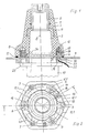
- a socket 1 of an inner cone plug coupling as is common for the connection of high-voltage cables in medium-voltage switchgear, has an insulating body 2 made of cast resin, in which an inner cone recess 3 is formed, which is open to an end face 4. At the opposite end, the inner cone recess 3 is followed by an axially identical plug contact part 5, which is to be connected to high-voltage internals in the encapsulated high-voltage device.
- Fastening fittings 6 and 7, which are axially parallel to the central axis 8 of the inner cone recess, are incorporated into the insulating body 2 from the end face 4. The fastening fittings are located on circular lines concentric to the opening of the inner cone recess, radially outside the inner cone recess.
- the end face 4 of the socket 1 lies in one plane on a wall 9 of a housing, within which there are high-voltage switchgear parts.
- this wall 9 is provided with a corresponding opening through which a cable connector 10 can be inserted from the outside.
- a hat-shaped field control body 11 is also attached to the high-voltage plug contact part 5, which is also embedded in the insulating body 2 and encompasses the adjacent section of the inner cone recess in a ring.
- an electrode 12 which is electrically insulated from it, is arranged in the region of the end face 4 and is arranged around the inner cone recess 3.
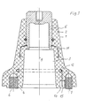
- this electrically insulated electrode 12 is formed from a plurality of partial electrodes 12.1 which are arranged in the circumferential direction between adjacent fastening fittings 6 and 7. These partial electrodes 12.1 are electrically connected to one another via a connecting line 13, the electrical connecting line 13 being embedded within the insulating body 2 in the insulating compound.
- the electrodes 12 and the connecting conductor 13 are preferably made of sieve or grid-like material, so that there is an intimate embedding that prevents the insulating compound from separating from the electrode or the connecting line during the shrinking process during the curing of the casting resin and forming dielectric defects will.
- the partial electrodes 12.1 can extend in the radial direction over the same area as the fastening fittings and, on the other hand, largely take up the space between adjacent fastening fittings 6, 7 and in the axial direction as far as into the insulating body 2 as the fittings 6, 7. This results in an extensive symmetrization of the electrical field, after which the gaps between adjacent fastening electrodes 6, 7 are then provided with electrically conductive parts which, at least approximately like the fastening fittings, are electrically almost at ground potential.
- the partial electrodes 12.1 are hood-shaped and are directed toward the field control body 11 with the rounded end. The rounding contributes to the favorable field distribution and forms a relatively large area compared to the field control body, the one corresponding high capacity value.
- the low capacitive resistance value achieved in this way enables the pending high voltage to be detected with relatively simple measuring devices.
- the connecting line 13, which also serves as an assembly aid for the positioning of the partial electrodes 12.1 in a casting mold, is flattened in the radial area of fastening fittings 6, deviating from the circular ring shape, and is provided on the flattened part with a small support insulator 14, which is fixed to the fastening fittings 6 concerned, around the Center electrodes 12.1 during the casting process of the insulating body 2.
- a connecting lug is attached to the connecting conductor 13, which protrudes into the space enclosed by the respective partial electrode 12 and is axially aligned is arranged to the inner cone recess in a recess 16 which is open to the end face 4.
- the connecting lug 15 also points with its free end to the end face 4.
- the respective terminal lug can be inserted into a holder corresponding to the recess 16, which is located within the casting mold which is used to produce the insulating body 2 with the internals.
- the connecting line 13 is located in the area which lies between the wall of the inner cone recess 3 and the fastening fittings 6, 7. In the axial direction, the connecting line 13 does not extend beyond the fastening fittings 6, 7.
- the socket 1 is fixed to the wall 9 with the interposition of a sealing ring 17.
- a spacer ring 18 is attached from the opposite side of the wall, which engages under the end face 4 with its radially inner part and with the radially outer part Part rests on the wall 9.
- This spacer ring 18 has an opening 19 which is aligned with the respective connecting lug 15 and merges into a groove 20 which extends radially outward. Through the opening 19, a plug 21 can thus be plugged into the terminal lug 15, from which an electrical line 22 can be guided through the groove 20 to a measuring device, not shown.
- a flange 23 of the cable connector 10 is seated on the spacer ring 18, a screw being able to be screwed into the associated fastening fitting 7 through the flange 23 and the spacer ring 18 and the wall 9.
- the socket 1 is fixed on the wall 9 via the spacer ring 18.
- the cable connector 10 has an electrical shield 24 which is guided in the outer jacket region and is connected to earth potential and extends axially beyond the connecting line 13 into the inner cone recess 3. It thus shields not only the connecting line 13 but also adjacent areas of the partial electrodes 12.1 from a conductor running axially within the cable connector 10.
- This conductor thus does not have a direct capacitive effect on the connecting line 13 or the relevant area of the partial electrodes 12.1, so that the voltage measured at the partial electrodes 12.1 is largely independent of whether the cable connector 10 is inserted into the socket 1 or not.
- the capacitive coupling thus takes place even when the cable connector 10 is inserted via the rounded ends of the partial electrodes 12.1 directly facing the field control body 11.
- the arrangement of the shield 24 in relation to the connecting line 13 and the partial electrodes 12.1 thus largely shields the electrical field generated by the cable connector 10 from the electrode 12.
- a socket is shown in FIG. 3, in which the electrode 12 lies within the insulating body 2 in the electrical field area between the fastening fittings 6, 7 and the field control body 11.
- the electrode 12 is ring-shaped and is concentric with the axis 8 of the inner cone recess 3. It engages radially in the area that lies between the wall of the inner cone recess and a fastening fitting 7 that is displaced radially further outward.
- the electrode 12 extends into its radial area, but is axially spaced therefrom.
- the electrode 12 can preferably consist of a wire helix, between the individual windings of which the casting resin can penetrate and which does not lose the intimate connection with the casting resin when the casting resin composition shrinks during the curing process.
- the electrode 12 can also be connected to fastening fittings 6, 7 via adapted support insulators.
Abstract
Description
Die Erfindung betrifft eine Steckbuchse gemäß dem Oberbegriff des ersten Anspruchs.The invention relates to a socket according to the preamble of the first claim.
Bei einer bekannten Steckbuchse dieser Art (DE-38 44 890 A1) durchdringt ein Isolierkörper einen Durchbruch in der Wandung eines Hochspannungsgerätes. Der Isolierkörper weist eine stirnseitige Öffnung einer Innenkonusausnehmung auf, in die ein Kabelstecker einführbar ist. Mit einem in der Innenkonusausnehmung angeordneten Steckkontakt ist ein hutförmiger Feldsteuerkörper verbunden, der in den Isolierkörper eingebettet ist und dessen freier Rand zu der der Gehäusewand benachbarten Stirnseite hinweist. Konzentrisch zur Öffnung der Innenkonusausnehmung sind in den Isolierkörper achsparallel gerichtet Befestigungsarmaturen eingegossen, über welche die Steckbuchse an der Gehäusewand bzw. der Kabelstecker unter Einfügung eines Druckringes festgeschraubt wird. Dabei ist anstelle einer Befestigungsarmatur eine gegenüber der Stirnseite zurückgesetzte Elektrode vorgesehen, die einerseits kapazitiv mit dem Feldsteuerkörper gekoppelt und andererseits über eine elektrische Steckverbindung mit außerhalb des Gerätegehäuses angeordneten elektrischen Meßeinrichtungen verbunden ist. Die Stirnseite des Isolierkörpers sitzt im übrigen unter Zwischenlage einer Dichtung gasdicht auf der Gehäusewand auf. Aufgrund der erforderlichen Hochspannungsdurchschlagsfestigkeit muß die Elektrode vom Feldsteuerkörper einen erheblichen Abstand aufweisen. Das hat zur Folge, daß der zwischen der Elektrode und dem Feldsteuerkörper gegebene elektrische Kapazitätswert sehr gering und damit der kapazitive Widerstand sehr hoch ist. Dadurch sind hochempfindliche Meßeinrichtungen zur Erfassung der am Steckkontakt anstehenden Spannung erforderlich, wobei die kapazitive Belastung durch die Erdkapazitäten benachbarter geerdeter Teile und der geschirmten elektrischen Leitung von der Elektrode bis zum Meßgerät beachtlich ist. Außerdem ist der Kopf der Elektrode kugelförmig erweitert, so daß das Profil der Befestigungsarmaturen in radialer Richtung entsprechend weit überschritten wird.In a known socket of this type (DE-38 44 890 A1), an insulating body penetrates an opening in the wall of a high-voltage device. The insulating body has an end opening of an inner cone recess into which a cable connector can be inserted. A hat-shaped field control body is connected to a plug contact arranged in the inner cone recess, which is embedded in the insulating body and the free edge of which points towards the end face adjacent to the housing wall. Concentric to the opening of the inner cone recess, fastening fittings are cast into the insulating body, which are oriented parallel to the axis and by means of which the socket is screwed onto the housing wall or the cable plug with the insertion of a pressure ring. Instead of a fastening fitting, an electrode set back relative to the end face is provided, which is capacitively coupled on the one hand to the field control body and on the other hand is connected via an electrical plug connection to electrical measuring devices arranged outside the device housing. The end face of the insulating body is seated gas-tight on the housing wall with the interposition of a seal. Due to the high dielectric strength required, the Electrode from the field control body have a considerable distance. The consequence of this is that the electrical capacitance value between the electrode and the field control body is very low, and thus the capacitance is very high. As a result, highly sensitive measuring devices are required to detect the voltage present at the plug contact, the capacitive load due to the earth capacitance of adjacent earthed parts and the shielded electrical line from the electrode to the measuring device being considerable. In addition, the head of the electrode is expanded in a spherical shape, so that the profile of the fastening fittings is exceeded correspondingly far in the radial direction.
Der Erfindung liegt die Aufgabe zugrunde, bei einer Steckbuchse gemäß dem Oberbegriff des ersten Anspruchs Maßnahmen zu treffen, durch welche eine Erhöhung des Kapazitätswertes der Elektrodenanordnung ohne nachteilige Beeinflussung des elektrischen Feldbildes erzielt wird.The invention has for its object to take measures in a socket according to the preamble of the first claim, by means of which an increase in the capacitance value of the electrode arrangement is achieved without adversely affecting the electrical field image.
Die Lösung dieser Aufgabe erfolgt gemäß der Erfindung durch die kennzeichnenden Merkmale des ersten Anspruchs.This object is achieved according to the invention by the characterizing features of the first claim.
Bei einem Aufbau einer Steckbuchse gemäß der Erfindung wird durch die Anordnung einer Elektrode um die Innenkonusausnehmung herum eine großflächige Kopplung zum Steckkontakt bzw. dem damit verbundenen Feldsteuerkörper und damit eine wesentliche Erhöhung des Kapazitätswertes erreicht. Vorzugsweise weist die Elektrode mehrere einzelne Teilelektroden auf, die in Umfangsrichtung zwischen benachbarten Befestigungsarmaturen angeordnet und untereinander elektrisch verbunden sind. Hierdurch wird eine fast vollständige Anpassung des elektrischen Feldbildes an das bereits von den Befestigungsarmaturen vorgegebene elektrische Feldbild erreicht. Dadurch wird auch zur Homogenisierung des Feldbildes beigetragen, weil sich nun auch zwischen den einzelnen Befestigungsarmaturen Elektrodenabschnitte befinden. Es ergibt sich dadurch eine der idealen Ringelektrode angenäherte Gesamtelektrodenform mit der daraus resultierenden gleichmäßigen Feldverteilung. Das Elektroden-Gesamtprofil braucht dabei nicht über das von den Befestigungsarmaturen vorgegebene radiale Profil hinauszuragen. Die Teilelektroden sind vorzugsweise haubenförmig ausgebildet und mit dem gerundeten Ende zum Feldsteuerkörper hin gerichtet, der am Ende der Innenkonusausnehmung mit einem hochspannungsführenden Steckkontaktteil verbunden ist. Durch die Rundung der Teilelektroden ergibt sich eine zum Feldsteuerkörper hingerichtete große Fläche, welche den Kapazitätswert erhöht und zudem eine günstige elektrische Feldverteilung. Die Elektroden bestehen vorzugsweise aus Sieb- oder gitterartigem Material, so daß eine innige, ablösungsfreie Verbindung mit dem für die Herstellung des Isolierkörpers verwendeten Gießharzs eintritt. Die Verbindungsleitung der einzelnen Teilelektroden kann zwischen den Befestigungsarmaturen und der Mantelfläche der Innenkonusausnehmung verlaufen. Dabei kann im Bereich von Befestigungsarmaturen der vorzugsweise als Bandleitung ausgebildete Verbindungsleiter im Bereich von Befestigungsarmaturen abgeflacht und dort über kleine Isolierstützer an der betreffenden Befestigungsarmatur vor dem Eingießen in das Gießharzs festgelegt werden. Vorzugsweise ist jedoch die Verbindungsleitung im Bereich von zwei Teilelektroden mit je einer Anschlußfahne versehen, die achsengleich zur Innenkonusausnehmung angeordnet ist und in einer zur Stirnseite offenen Aussparung zur Stirnseite hinweist. In der Gießform kann so der Verbindungsleiter mit den daran befestigten Teilelektroden an einer entsprechend ausgebildeten Haltevorrichtung in der Gießform bis zum Erstarren der Gießharzmasse gehalten werden. An wenigstens eine der Anschlußfahnen kann dann nach dem Entformen aus der Gießform ein Stecker für den Anschluß eines Meßgerätes angesteckt werden. Für die Montage der Steckbuchse an einer entsprechend durchbrochenen Gerätewand wird als Gegenlage an die Stirnseite ein Abstandsring angesetzt, wobei zwischen die Stirnseite und den Abstandsring der Rand der für das Einführen eines Kabelsteckers erforderliche Durchbruch ragt. Der Abstandsring dient dabei zur gleichmäßigen Druckverteilung über den Umfang des Durchbruchs, so daß die Stirnseite der Steckbuchse mit einer dort vorgesehenen Ringdichtung über den gesamten Umfang gasdicht an die betreffende Gehäusewand angepreßt wird, wenn die Schrauben in die zugehörigen Befestigungsarmaturen vom Abstandsring her eingeschraubt sind. Die Anordnung der Verbindungsleitung und gegebenenfalls von Bereichen der Teilelektroden ist so getroffen, daß sie im Feldschatten einer Abschirmung liegen, die mit dem Einführen eines Kabelsteckers in die Innenkonusausnehmung mit eingeführt wird. Diese geerdete Abschirmung verhindert, daß ein innerhalb des Kabelsteckers geführter Leiter kapazitiv mit der Verbindungsleitung bzw. benachbarten Bereichen der Teilelektroden gekoppelt ist. Dadurch wird der für die Spannungsankopplung gewünschte Kapazitätswert insbesondere durch die Geometrie zwischen dem Feldsteuerkörper und den Teilelektroden bestimmt. Es wird somit der über die Teilelektroden erfaßte Hochspannungswert nur geringfügig geändert, wenn der Kabelstecker eingeführt oder herausgezogen ist.In the construction of a plug socket according to the invention, a large-area coupling to the plug contact or the associated field control body and thus a substantial increase in the capacitance value is achieved by the arrangement of an electrode around the inner cone recess. The electrode preferably has a plurality of individual partial electrodes, which are arranged in the circumferential direction between adjacent fastening fittings and are electrically connected to one another. In this way, an almost complete adaptation of the electrical field image to the electrical field image already specified by the fastening fittings is achieved. This also contributes to the homogenization of the field image, because there are now electrode sections between the individual fastening fittings. This results in an overall electrode shape approximating the ideal ring electrode with the resulting uniform field distribution. The overall electrode profile need not protrude beyond the radial profile specified by the fastening fittings. The partial electrodes are preferably hood-shaped and with the rounded end directed towards the field control body, which is connected to a high-voltage plug-in contact part at the end of the inner cone recess. The rounding of the partial electrodes results in a large area which is executed for the field control body, which increases the capacitance value and also a favorable electrical field distribution. The electrodes are preferably made of sieve or grid-like material, so that an intimate, detachment-free connection occurs with the casting resin used for the production of the insulating body. The connecting line of the individual partial electrodes can run between the fastening fittings and the outer surface of the inner cone recess. In the area of fastening fittings, the connecting conductor, which is preferably in the form of a ribbon cable, can be flattened in the region of fastening fittings and fixed there using small insulation supports on the fastening fitting concerned before it is poured into the casting resin. However, the connecting line is preferably provided in the region of two partial electrodes with a connecting lug each, which is arranged axially with the inner cone recess and points to the end face in a recess open to the end face. In the casting mold, the connecting conductor with the partial electrodes attached to it can be held in a correspondingly designed holding device in the casting mold until the casting resin mass solidifies. At least one of the connecting lugs can then be removed from the Cast a plug for connecting a measuring device to be plugged in. To mount the socket on a correspondingly perforated device wall, a spacer ring is placed on the end face as a counterpart, the edge of the breakthrough required for the insertion of a cable plug protruding between the end face and the spacer ring. The spacer ring is used for uniform pressure distribution over the circumference of the opening, so that the end face of the socket with an annular seal provided there is pressed gas-tight over the entire circumference to the relevant housing wall when the screws are screwed into the associated fastening fittings from the spacer ring. The arrangement of the connecting line and, if appropriate, areas of the partial electrodes is such that they lie in the field shadow of a shield, which is inserted into the inner cone recess when a cable connector is inserted. This grounded shield prevents a conductor guided inside the cable connector from being capacitively coupled to the connecting line or adjacent areas of the partial electrodes. As a result, the capacitance value desired for the voltage coupling is determined in particular by the geometry between the field control body and the partial electrodes. The high-voltage value detected via the partial electrodes is thus changed only slightly when the cable plug is inserted or removed.
Die Erfindung ist nachfolgend anhand der Zeichnungen von Ausführungsbeispielen näher erläutert.The invention is explained in more detail below with reference to the drawings of exemplary embodiments.
Es zeigen:
- Fig. 1 einen Längsschnitt durch eine an eine Gehäusewand angesetzte Steckbuchse,
- Fig. 2 eine Draufsicht auf die freie Stirnseite der Steckbuchse nach Figur 1 mit Darstellung der Einzelteile nach Art einer Röntgenaufnahme und
- Fig. 3 einen Längsschnitt durch eine Steckbuchse mit geänderter Elektrodenausführung.
- 1 shows a longitudinal section through a socket attached to a housing wall,
- Fig. 2 is a plan view of the free end face of the socket of Figure 1 showing the individual parts in the manner of an X-ray and
- Fig. 3 shows a longitudinal section through a socket with a modified electrode design.
Eine Steckbuchse 1 einer Innenkonus-Steckkupplung, wie sie für den Anschluß von Hochspannungskabeln in Mittelspannungsschaltanlagen üblich ist, weist einen aus Gießharz hergestellten Isolierkörper 2 auf, in dem eine Innenkonusausnehmung 3 ausgeformt ist, die zu einer Stirnseite 4 hin offen ist. Am gegenüberliegenden Ende schließt sich an die Innenkonusausnehmung 3 ein achsengleiches Steckkontaktteil 5 an, das mit hochspannungsführenden Einbauten in dem gekapselten Hochspannungsgerät zu verbinden ist. Von der Stirnseite 4 aus sind in den Isolierkörper 2 Befestigungsarmaturen 6 bzw. 7 eingearbeitet, die achsparallel zur Mittelachse 8 der Innenkonusausnehmung stehen. Die Befestigungsarmaturen befinden sich auf konzentrisch zur Öffnung der Innenkonusausnehmung verlaufenden Kreislinien radial außerhalb der Innenkonusausnehmung. Die Stirnfläche 4 der Steckbuchse 1 liegt in einer Ebene auf einer Wandung 9 eines Gehäuses auf, innerhalb welchem sich Hochspannungsschaltanlagenteile befinden. Im Bereich der Innenkonusausnehmung ist diese Wand 9 mit einem entsprechenden Durchbruch versehen, durch den von außen ein Kabelstecker 10 eingeführt werden kann. An den hochspannungsführenden Steckkontaktteil 5 ist zudem ein hutförmiger Feldsteuerkörper 11 angesetzt, der ebenfalls in den Isolierkörper 2 eingebettet ist und ringförmig den benachbarten Abschnitt der Innenkonusausnehmung umgreift.A socket 1 of an inner cone plug coupling, as is common for the connection of high-voltage cables in medium-voltage switchgear, has an
Um einen kapazitiven Spannungsabgriff zur Messung der am Steckkontaktteil 5 bzw. dem Feldsteuerkörper 11 anliegenden Hochspannung zu schaffen, ist als kapazitiv wirkender Gegenbelag zum Feldsteuerkörper 11 eine davon elektrisch isolierte Elektrode 12 im Bereich der Stirnseite 4 angeordnet, die um die Innenkonusausnehmung 3 herum angeordnet ist.By a capacitive voltage tap for measuring those applied to the
Diese elektrisch isolierte Elektrode 12 ist gemäß Figur 2 aus mehreren Teilelektroden 12.1 gebildet, die in Umfangsrichtung zwischen benachbarten Befestigungsarmaturen 6 bzw. 7 angeordnet sind. Diese Teileelektroden 12.1 stehen über eine Verbindungsleitung 13 miteinander in elektrischer Verbindung, wobei die elektrische Verbindungsleitung 13 innerhalb des Isolierkörpers 2 in die Isoliermasse eingebettet ist. Die Elektroden 12 wie der Verbindungsleiter 13 bestehen vorzugsweise aus sieb- oder gitterartigem Material, so daß sich eine innige Einbettung ergibt, die verhindert, daß sich beim Schrumpfungsprozeß während des Aushärtens des Gießharzes die Isoliermasse von der Elektrode bzw. der Verbindungsleitung trennt und dielektrische Fehlstellen gebildet werden. Die Teilelektroden 12.1 können sich dabei in radialer Richtung über den gleichen Bereich wie die Befestigungsarmaturen erstrecken und andererseits weitgehende den Raum zwischen benachbarten Befestigungsarmaturen 6,7 einnehmen sowie in axialer Richtung soweit in den Isolierkörper 2 wie die Armaturen 6,7. Es ergibt sich dadurch eine weitgehende Symmetrierung des elektrischen Feldes, nachdem dann auch die Zwischenräume zwischen benachbarten Befestigungselektroden 6,7 mit elektrisch leitenden Teilen versehen sind, die zumindest annähernd wie die Befestigungsarmaturen elektrisch fast an Massepotential liegen. Dabei sind die Teilelektroden 12.1 haubenförmig ausgebildet und mit dem gerundeten Ende zum Feldsteuerkörper 11 gerichtet. Die Rundung trägt dabei zur günstigen Feldverteilung bei und bildet gegenüber dem Feldsteuerkörper eine relativ große Fläche, die einen entsprechenden hohen Kapazitätswert mit sich bringt. Der dadurch erzielte geringe kapazitive Widerstandswert ermöglicht die Erfassung der anstehenden Hochspannung mit relativ einfachen Meßeinrichtungen. Die zugleich als Montagehilfe für die Positionierung der Teilelektroden 12.1 in einer Gießform dienende Verbindungsleitung 13 ist im radialen Bereich von Befestigungsarmaturen 6 abweichend von der Kreisringform abgeflacht und am abgeflachten Teil mit einem kleinen Stützisolator 14 versehen, der an den betreffenden Befestigungsarmaturen 6 festgelegt ist, um die Teilelektroden 12.1 während des Gießvorganges des Isolierkörpers 2 zu zentrieren. Vorzugsweise wird zur Positionierung der Teilelektroden 12 in der betreffenden Gießform jedoch anstelle der Stützisolatoren 14 im Bereich mindestens einer, vorzugsweise jedoch im Bereich mehrerer Teilelktroden 12.1 eine Anschlußfahne an den Verbindungsleiter 13 angebracht, die in den von der jeweiligen Teilelektrode 12 umschlossenen Raum ragt und die achsengleich zur Innenkonusausnehmung in einer Aussparung 16 angeordnet ist, die zur Stirnseite 4 hin offen ist. Auch die Anschlußfahne 15 weist mit ihrem freien Ende zur Stirnseite 4 hin. Dadurch kann die jeweilige Anschlußfahne in eine der Aussparung 16 entsprechende Halterung eingesteckt werden, der sich innerhalb der Gießform befindet, die zur Herstellung des Isolierkörpers 2 mit den Einbauten dient. Die Verbindungsleitung 13 befindet sich in den Bereich, der zwischen der Wandung der Innenkonusausnehnung 3 und den Befestigungsarmaturen 6,7 liegt. In achsialer Richtung greift die Verbindungsleitung 13 nicht über die Befestigungsarmaturen 6,7 hinaus.According to FIG. 2, this electrically insulated
Die Steckbuchse 1 wird an der Wand 9 unter Zwischenlage eines Dichtungsringes 17 festgesetzt. Dazu wird von der gegenüberliegenden Seite der Wand aus ein Abstandsring 18 angesetzt, der mit seinem radial innen liegenden Teil die Stirnseite 4 untergreift und mit dem radial außen liegenden Teil auf der Wand 9 aufliegt. Dieser Abstandsring 18 weist einen mit der jeweiligen Anschlußfahne 15 fluchtenden Durchbruch 19 auf, der in eine radial nach außen verlaufende Nut 20 übergeht. Durch den Durchbruch 19 kann somit ein Stecker 21 an die Anschlußfahne 15 angesteckt werden, von dem eine elektrische Leitung 22 durch die Nut 20 zu einem nicht dargestellten Meßgerät geführt werden kann. Auf dem Abstandsring 18 sitzt andererseits ein Flansch 23 des Kabelsteckers 10 auf, wobei durch den Flansch 23 und den Abstandsring 18 sowie die Wand 9 hindurch je eine Schraube in die zugeordnete Befestigungsarmatur 7 eingedreht werden kann. Über die Befestigungsarmaturen 6 wird Steckbuchse 1 für sich über den Abstandring 18 an der Wand 9 festgesetzt. Der Kabelstecker 10 weist dabei eine im äußeren Mantelbereich geführte elektrische Abschirmung 24 auf, die an Erdpotential angeschlossen ist und axial bis über die Verbindungsleitung 13 hinaus in die Innenkonusausnehmung 3 reicht. Sie schirmt somit nicht nur die Verbindungsleitung 13 sondern auch benachbarte Bereiche der Teilelektroden 12.1 gegenüber einem innerhalb des Kabelsteckers 10 axial verlaufenden Leiter ab. Dieser Leiter wirkt somit nicht unmittelbar kapazitiv auf die Verbindungsleitung 13 bzw. die betreffenden Bereich der Teilelektroden 12.1, so daß die an den Teilelektroden 12.1 gemessene Spannung weitgehend unabhängig ist, ob der Kabelstecker 10 in die Steckbuchse 1 eingeführt ist oder nicht. Die kapazitive Kopplung erfolgt somit auch bei eingestecktem Kabelstecker 10 über die dem Feldsteuerkörper 11 direkt zugewandten gerundeten Enden der Teilelektroden 12.1. Die Abschirmung 24 bewirkt somit durch ihre Anordnung gegenüber der Verbindungsleitung 13 und den Teilelektroden 12.1 eine weitgehende Abschattung des vom Kabelsteckers 10 erzeugten elektrischen Feldes gegenüber der Elektrode 12.The socket 1 is fixed to the
Bei sonst gleichem Aufbau ist in Figur 3 eine Steckbuchse dargestellt, bei welcher die Elektrode 12 innerhalb des Isolierkörpers 2 im elektrischen Feldbereich zwischen den Befestigungsarmaturen 6,7 und dem Feldsteuerkörper 11 liegt. Die Elektrode 12 ist dabei ringförmig ausgebildet und liegt konzentrisch zur Achse 8 der Innenkonusausnehmung 3. Sie greift dabei radial in den Bereich, der zwischen der Wandung der Innenkonusausnehmung und einer radial weiter nach außen verlagerten Befestigungsarmatur 7 liegt. Die Elektrode 12 reicht jedoch im Bezug auf die weiteren Befestigunsarmaturen 6, welche auf einem kleineren Kreisbogen angeordnet sind, bis in deren radialen Bereich, ist jedoch axial davon beabstandtet. Im Bereich der radial nach außen verlagerten Befestigungsarmatur ergibt sich so die Möglichkeit, die Aussparung 16 für wenigstens eine Anschlußfahne 15 in diesen Bereich anzuordnen. Die Elektrode 12 kann dabei vorzugsweise aus einer Drahtwendel bestehen, zwischen deren einzlne Windungen das Gießharz eindringen kann und die bei der Schrumpfung der Gießharzmasse während des Aushärteprozesses die innige Verbindung mit dem Gießharz nicht verliert. Zur Fixierung vor dem Gießen des Isolierkörpers 2 kann auch hierbei die Elektrode 12 über angepaßte Stütisolatoren mit Befestigungsarmaturen 6,7 verbunden sein.With an otherwise identical structure, a socket is shown in FIG. 3, in which the
Claims (13)
Applications Claiming Priority (2)
| Application Number | Priority Date | Filing Date | Title |
|---|---|---|---|
| DE4009358 | 1990-03-23 | ||
| DE4009358A DE4009358C2 (en) | 1990-03-23 | 1990-03-23 | Socket |
Publications (3)
| Publication Number | Publication Date |
|---|---|
| EP0447910A2 true EP0447910A2 (en) | 1991-09-25 |
| EP0447910A3 EP0447910A3 (en) | 1992-02-26 |
| EP0447910B1 EP0447910B1 (en) | 1995-07-05 |
Family
ID=6402899
Family Applications (1)
| Application Number | Title | Priority Date | Filing Date |
|---|---|---|---|
| EP91103671A Expired - Lifetime EP0447910B1 (en) | 1990-03-23 | 1991-03-11 | Plug socket |
Country Status (5)
| Country | Link |
|---|---|
| EP (1) | EP0447910B1 (en) |
| JP (1) | JPH05129047A (en) |
| DE (2) | DE4009358C2 (en) |
| FI (1) | FI104348B (en) |
| NO (1) | NO302006B1 (en) |
Cited By (1)
| Publication number | Priority date | Publication date | Assignee | Title |
|---|---|---|---|---|
| EP0572692A1 (en) * | 1991-03-28 | 1993-12-08 | Karl Pfisterer Elektrotechnische Spezialartikel Gmbh & Co. Kg | Connector socket |
Families Citing this family (8)
| Publication number | Priority date | Publication date | Assignee | Title |
|---|---|---|---|---|
| DE4235044C2 (en) * | 1992-10-17 | 2002-06-20 | Alstom Sachsenwerk Gmbh | receptacle |
| DE4312618A1 (en) * | 1993-04-19 | 1994-10-20 | Abb Patent Gmbh | Cable plug socket |
| DE19737426B4 (en) * | 1997-08-21 | 2005-05-04 | Siemens Ag | Socket for medium-voltage switchgear |
| DE19805068A1 (en) * | 1998-02-10 | 1999-08-12 | Abb Patent Gmbh | Cable sleeve |
| KR20160099573A (en) | 2013-12-18 | 2016-08-22 | 바스프 코팅스 게엠베하 | Pigment pastes containing an aqueous dispersion of a mixed polymer |
| DE102014004284B4 (en) * | 2014-03-26 | 2019-11-14 | Lapp Insulators Gmbh | High-voltage bushing |
| DE102016205535A1 (en) | 2016-04-04 | 2017-10-05 | Siemens Aktiengesellschaft | High-voltage bushing |
| CN109451647B (en) * | 2018-11-01 | 2020-08-07 | 中国人民解放军国防科技大学 | High current diode cone ceramic package vacuum interface insulation structure |
Citations (3)
| Publication number | Priority date | Publication date | Assignee | Title |
|---|---|---|---|---|
| DE3247673A1 (en) * | 1982-12-23 | 1984-07-05 | Karl Pfisterer Elektrotechnische Spezialartikel Gmbh & Co Kg, 7000 Stuttgart | Plug socket |
| DE3611462A1 (en) * | 1986-04-05 | 1987-10-15 | Pfisterer Elektrotech Karl | Connecting fitting for conductors of a medium-voltage or high-voltage network |
| DE3644890A1 (en) * | 1986-04-05 | 1987-11-12 | Pfisterer Elektrotech Karl | Connecting fitting for conductors of a medium-voltage or high-voltage network |
Family Cites Families (5)
| Publication number | Priority date | Publication date | Assignee | Title |
|---|---|---|---|---|
| DE2732268C2 (en) * | 1977-07-16 | 1982-06-03 | Kabel- Und Lackdrahtfabriken Gmbh, 6800 Mannheim | Cable termination |
| DE2943080C2 (en) * | 1979-10-25 | 1982-04-08 | Karl Pfisterer Elektrotechnische Spezialartikel Gmbh & Co Kg, 7000 Stuttgart | Set for the end of a medium-voltage or high-voltage cable |
| DE2915369B1 (en) * | 1979-04-14 | 1980-09-18 | Pfisterer Elektrotech Karl | Set for the end of a medium or high voltage cable |
| DE3110660C2 (en) * | 1981-03-19 | 1983-07-14 | Karl Pfisterer Elektrotechnische Spezialartikel Gmbh & Co Kg, 7000 Stuttgart | Set for the end of a medium or high voltage cable |
| DE3445905A1 (en) * | 1984-12-15 | 1986-06-26 | Karl Pfisterer Elektrotechnische Spezialartikel Gmbh & Co Kg, 7000 Stuttgart | Coupling |
-
1990
- 1990-03-23 DE DE4009358A patent/DE4009358C2/en not_active Expired - Fee Related
-
1991
- 1991-03-11 EP EP91103671A patent/EP0447910B1/en not_active Expired - Lifetime
- 1991-03-11 DE DE59105896T patent/DE59105896D1/en not_active Expired - Fee Related
- 1991-03-22 NO NO911169A patent/NO302006B1/en unknown
- 1991-03-22 JP JP3058702A patent/JPH05129047A/en active Pending
- 1991-03-22 FI FI911400A patent/FI104348B/en active
Patent Citations (3)
| Publication number | Priority date | Publication date | Assignee | Title |
|---|---|---|---|---|
| DE3247673A1 (en) * | 1982-12-23 | 1984-07-05 | Karl Pfisterer Elektrotechnische Spezialartikel Gmbh & Co Kg, 7000 Stuttgart | Plug socket |
| DE3611462A1 (en) * | 1986-04-05 | 1987-10-15 | Pfisterer Elektrotech Karl | Connecting fitting for conductors of a medium-voltage or high-voltage network |
| DE3644890A1 (en) * | 1986-04-05 | 1987-11-12 | Pfisterer Elektrotech Karl | Connecting fitting for conductors of a medium-voltage or high-voltage network |
Cited By (1)
| Publication number | Priority date | Publication date | Assignee | Title |
|---|---|---|---|---|
| EP0572692A1 (en) * | 1991-03-28 | 1993-12-08 | Karl Pfisterer Elektrotechnische Spezialartikel Gmbh & Co. Kg | Connector socket |
Also Published As
| Publication number | Publication date |
|---|---|
| FI104348B1 (en) | 1999-12-31 |
| EP0447910B1 (en) | 1995-07-05 |
| NO911169L (en) | 1991-09-24 |
| EP0447910A3 (en) | 1992-02-26 |
| DE4009358C2 (en) | 1997-05-15 |
| NO302006B1 (en) | 1998-01-05 |
| DE59105896D1 (en) | 1995-08-10 |
| JPH05129047A (en) | 1993-05-25 |
| FI911400A (en) | 1991-09-24 |
| FI104348B (en) | 1999-12-31 |
| DE4009358A1 (en) | 1991-09-26 |
| FI911400A0 (en) | 1991-03-22 |
| NO911169D0 (en) | 1991-03-22 |
Similar Documents
| Publication | Publication Date | Title |
|---|---|---|
| EP0671061B1 (en) | Plug-type connecting device for cables | |
| DE2348895C2 (en) | Connection for power cables | |
| DE3544870A1 (en) | SPARK PLUG | |
| EP0060930B1 (en) | Fitting for the terminal of a medium-voltage or high-voltage cable | |
| EP0447910B1 (en) | Plug socket | |
| DE4435864C2 (en) | Set in the form of a bushing or a socket for cable plugs | |
| WO1995029405A1 (en) | Device for connecting a voltage display apparatus to a sensor | |
| DE3540547A1 (en) | High-voltage current transformer and a method for producing such a high-voltage current transformer | |
| EP0017953B1 (en) | Fitting for the end of a middle voltage or high voltage cable | |
| DE3935360C2 (en) | ||
| DE2410625A1 (en) | HV cable entry gland for sealed equipment - has hollow insulated cylinder with coil spring exerting force against bush on cable plug | |
| EP0459250B1 (en) | Cable end fitting | |
| EP1950770A2 (en) | Insulator | |
| EP0163053B1 (en) | Voltage surge arrester | |
| DE102020204620B4 (en) | cable connection | |
| DE4234461A1 (en) | Test adaptor esp. for gas-insulated medium-voltage switchgear - has recessed insulating sleeve fitted replaceably into hollowed end of tubular polymeric plug with coaxial conductor | |
| EP0572692A1 (en) | Connector socket | |
| DE3709544C2 (en) | ||
| DE2609079C2 (en) | Cable entry | |
| WO1992016953A1 (en) | Component for high voltage energy supply installations | |
| DE2928727A1 (en) | Termination for medium and high voltage cables - has circular monitoring electrode embedded in insulating ring around conical field control electrode inside insulator | |
| EP3400603B1 (en) | Winding arrangement with a plug lead-through | |
| DE4235044C2 (en) | receptacle | |
| DE3619789C1 (en) | Connecting device which can be connected to a bolt | |
| EP3266085B1 (en) | Field control element for end closures of cables for transmitting energy |
Legal Events
| Date | Code | Title | Description |
|---|---|---|---|
| PUAI | Public reference made under article 153(3) epc to a published international application that has entered the european phase |
Free format text: ORIGINAL CODE: 0009012 |
|
| AK | Designated contracting states |
Kind code of ref document: A2 Designated state(s): DE FR GB IT |
|
| PUAL | Search report despatched |
Free format text: ORIGINAL CODE: 0009013 |
|
| AK | Designated contracting states |
Kind code of ref document: A3 Designated state(s): DE FR GB IT |
|
| RAP1 | Party data changed (applicant data changed or rights of an application transferred) |
Owner name: AEG SACHSENWERK GMBH |
|
| 17P | Request for examination filed |
Effective date: 19920630 |
|
| 17Q | First examination report despatched |
Effective date: 19940415 |
|
| GRAA | (expected) grant |
Free format text: ORIGINAL CODE: 0009210 |
|
| AK | Designated contracting states |
Kind code of ref document: B1 Designated state(s): DE FR GB IT |
|
| REF | Corresponds to: |
Ref document number: 59105896 Country of ref document: DE Date of ref document: 19950810 |
|
| ET | Fr: translation filed | ||
| GBT | Gb: translation of ep patent filed (gb section 77(6)(a)/1977) |
Effective date: 19950829 |
|
| ITF | It: translation for a ep patent filed |
Owner name: MODIANO & ASSOCIATI S.R.L. |
|
| PLBE | No opposition filed within time limit |
Free format text: ORIGINAL CODE: 0009261 |
|
| STAA | Information on the status of an ep patent application or granted ep patent |
Free format text: STATUS: NO OPPOSITION FILED WITHIN TIME LIMIT |
|
| 26N | No opposition filed | ||
| PGFP | Annual fee paid to national office [announced via postgrant information from national office to epo] |
Ref country code: GB Payment date: 19990226 Year of fee payment: 9 |
|
| PGFP | Annual fee paid to national office [announced via postgrant information from national office to epo] |
Ref country code: FR Payment date: 19990318 Year of fee payment: 9 |
|
| PGFP | Annual fee paid to national office [announced via postgrant information from national office to epo] |
Ref country code: DE Payment date: 19990529 Year of fee payment: 9 |
|
| PG25 | Lapsed in a contracting state [announced via postgrant information from national office to epo] |
Ref country code: GB Free format text: LAPSE BECAUSE OF NON-PAYMENT OF DUE FEES Effective date: 20000311 |
|
| GBPC | Gb: european patent ceased through non-payment of renewal fee |
Effective date: 20000311 |
|
| PG25 | Lapsed in a contracting state [announced via postgrant information from national office to epo] |
Ref country code: FR Free format text: LAPSE BECAUSE OF NON-PAYMENT OF DUE FEES Effective date: 20001130 |
|
| REG | Reference to a national code |
Ref country code: FR Ref legal event code: ST |
|
| PG25 | Lapsed in a contracting state [announced via postgrant information from national office to epo] |
Ref country code: DE Free format text: LAPSE BECAUSE OF NON-PAYMENT OF DUE FEES Effective date: 20010103 |
|
| PG25 | Lapsed in a contracting state [announced via postgrant information from national office to epo] |
Ref country code: IT Free format text: LAPSE BECAUSE OF NON-PAYMENT OF DUE FEES;WARNING: LAPSES OF ITALIAN PATENTS WITH EFFECTIVE DATE BEFORE 2007 MAY HAVE OCCURRED AT ANY TIME BEFORE 2007. THE CORRECT EFFECTIVE DATE MAY BE DIFFERENT FROM THE ONE RECORDED. Effective date: 20050311 |