EP0447854B1 - Cutting device for a document shredder - Google Patents
Cutting device for a document shredder Download PDFInfo
- Publication number
- EP0447854B1 EP0447854B1 EP91102991A EP91102991A EP0447854B1 EP 0447854 B1 EP0447854 B1 EP 0447854B1 EP 91102991 A EP91102991 A EP 91102991A EP 91102991 A EP91102991 A EP 91102991A EP 0447854 B1 EP0447854 B1 EP 0447854B1
- Authority
- EP
- European Patent Office
- Prior art keywords
- cutting
- spacing
- mechanism according
- roller surface
- axial
- Prior art date
- Legal status (The legal status is an assumption and is not a legal conclusion. Google has not performed a legal analysis and makes no representation as to the accuracy of the status listed.)
- Expired - Lifetime
Links
Images
Classifications
-
- B—PERFORMING OPERATIONS; TRANSPORTING
- B02—CRUSHING, PULVERISING, OR DISINTEGRATING; PREPARATORY TREATMENT OF GRAIN FOR MILLING
- B02C—CRUSHING, PULVERISING, OR DISINTEGRATING IN GENERAL; MILLING GRAIN
- B02C18/00—Disintegrating by knives or other cutting or tearing members which chop material into fragments
- B02C18/06—Disintegrating by knives or other cutting or tearing members which chop material into fragments with rotating knives
- B02C18/16—Details
- B02C18/18—Knives; Mountings thereof
- B02C18/182—Disc-shaped knives
-
- B—PERFORMING OPERATIONS; TRANSPORTING
- B02—CRUSHING, PULVERISING, OR DISINTEGRATING; PREPARATORY TREATMENT OF GRAIN FOR MILLING
- B02C—CRUSHING, PULVERISING, OR DISINTEGRATING IN GENERAL; MILLING GRAIN
- B02C18/00—Disintegrating by knives or other cutting or tearing members which chop material into fragments
- B02C18/0007—Disintegrating by knives or other cutting or tearing members which chop material into fragments specially adapted for disintegrating documents
-
- Y—GENERAL TAGGING OF NEW TECHNOLOGICAL DEVELOPMENTS; GENERAL TAGGING OF CROSS-SECTIONAL TECHNOLOGIES SPANNING OVER SEVERAL SECTIONS OF THE IPC; TECHNICAL SUBJECTS COVERED BY FORMER USPC CROSS-REFERENCE ART COLLECTIONS [XRACs] AND DIGESTS
- Y10—TECHNICAL SUBJECTS COVERED BY FORMER USPC
- Y10T—TECHNICAL SUBJECTS COVERED BY FORMER US CLASSIFICATION
- Y10T83/00—Cutting
- Y10T83/768—Rotatable disc tool pair or tool and carrier
- Y10T83/7809—Tool pair comprises rotatable tools
- Y10T83/783—Tool pair comprises contacting overlapped discs
Definitions
- the invention relates to a cutting device for a document shredder according to the preamble of claim 1.
- a document shredder is to be understood here as a device which is primarily intended to cut documents and other flat material, in particular paper, into strips which are as illegible as possible. It can also be used to cut other objects.
- a cutting device of the type mentioned has become known from DE-C-19 53 681. It creates a so-called torsion cut, ie it cuts the documents into narrow strips that are more or less strong Assume a screw shape because the two edges of the strip are deflected in different directions after the cut.
- the cutting unit according to DE-C-19 53 681 has the advantage that even when cutting layers of several papers in the passage which is formed between two pairs of cutting disks, there is sufficient space for the strip to be there can walk freely.
- a problem is the relatively large cutting disc height above the roller surface, because this makes the cutting discs sensitive to breakage and increases the roller diameter, the roller spacing and thus the amount of space and construction costs. Relatively sharp transition edges between the back of the cutting flank and the surface of the cutting roller disrupt the friction and adhesion-free passage of the strips. Strips are observed to stick to and be taken around the cutting disks, so strippers are usually required to prevent them from wrapping around the cutting rollers.
- DE-U-88 13 569 shows a similar design, in which the passage has a very elongated cross-sectional shape.
- the transitions between the back flanks of the cutting disks and the roller surface have small fillets, but they do not change the problem described above.
- the object of the invention is to improve a cutting unit of the type mentioned in such a way that with good cutting results and as little energy expenditure as possible and low risk of breakage, a strip pass is possible without the tendency for the strips to get caught on the rollers.
- the defined, squat trapezoidal shape of the passage allows the strip to take almost any position. Its tendency to form screws is reduced and also in the event that material is cut which tends to stretch when cutting, the corrugated cutting edges can pass through the passage unhindered.
- the compact trapezoidal shape can be further defined on the basis of various other criteria which are specified in the subclaims. However, due to the different designs, they are also to be understood as alternative, although a particularly advantageous embodiment can be used in combination, since they are not mutually exclusive. It is also important to define the generous rounding of the transitions between the cutting and back flanks each cutting disc and the roller surface. It has been found that this significantly reduces the tendency for the strips to jam, although this was not initially believed because it somewhat reduces the largest diagonal dimension in the passageway.
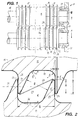
- FIG. 1 shows a cutting mechanism 11 with two cutting rollers 12, 13, each consisting of a roller body 16 with cutting disks 14, 15 formed integrally thereon.
- the roller bodies have on each side a journal 18 which is mounted in bearings 19 on a machine frame 20 of a document shredder which is not shown in further details.
- Fig. 1 it is indicated that the cutting rollers are axially supported against each other via a corresponding axially elastic bearing design of the bearing block 21 formed as a common bearing insert, so that they run against each other with as little friction as possible, but on the other hand also result in a good cutting profile and in the event of an overload can yield axially.
- the cutting disks 14, 15 are annular flange-like, preferably hardened structures projecting over the roller surface 17 of the continuous roller body 16, which have a cutting edge 22 running essentially in a radial plane and a back flank 23 running at an angle f with respect to this or a radial plane.
- the flanks 22, 23 are connected to one another by a cylindrical annular surface 24 forming the outer circumference of the cutting disk, which has a relatively small width s in the axial direction.
- the cutting disks are made in one piece with the roller body. However, they could also be lined up on a shaft in the form of individual disks, if this is cheaper for manufacturing reasons.
- the transition between the back flanks 23 and the cutting flanks 22 and the roller surface 17 is provided with generous fillets 45, namely with a radius r that is greater than one fifth of the cutting disc height h above the roller surface 17 (preferably, as in the exemplary embodiment, about a third of h ; see Fig. 2).
- the cutting flanks 22 of the cutting disks 14 of a cutting roller 12 rest against the corresponding cutting flanks 22 of the cutting disks 15 of the cutting roller 13, since these are in the same axial direction on both cutting rollers Distance b are arranged from each other.
- the cutting flanks 22 form a circumferential circular cutting edge 25 between them and the annular surface 24, which is determining for the distance dimension b .
- the cutting flank 22 runs essentially radially, but could also be designed differently if a low-friction engagement of the two cutting edge regions is ensured. For example, an even more generous fillet would be possible.
- This passage has a compact trapezoidal shape with corners rounded by the fillets 45, ie it approaches an equilateral trapezoid rather than an elongated strip-like one. This is achieved by the relatively steep course of the back flanks 23 together with a moderate cutting disc height h .
- the cutting rollers 12, 13 are arranged with an axial spacing A which is smaller than their outer diameter Da . This creates a lenticular overlap zone between the cutting disks, the largest dimension of which 2 has the dimension u in the connecting plane of the two cutting disc axes 30 shown in FIG. 2.
- the dimensions of the passage are also to be understood in this level, since it has its narrowest point in this level and widens in front of and behind it.
- the cutting disk height h can be approximately 2.5 mm with an axial cutting edge distance b of 4 mm.
- a center distance A of 23.5 mm there is an overlap u of 1.5 mm and thus a radial dimension d of the passage of 2.5 mm, while the dimension a , ie the smallest distance between the back flanks 23 in the passage 29 2, 6 mm.
- This small ring area also facilitates the cutting work by increasing the surface pressure in the cutting area.
- the relatively small width s of the annular surface 24 ensures that no pronounced corners are formed in the passage, which could give it a Z-shape.
- the dimension ratios apply, which are calculated from the previously specified data leave, also as particularly advantageous. Deviating from this, however, the values can differ.
- the flank angle can be selected between 20 and 35 ° without, on the one hand, increasing the risk of breakage too much or restricting the passage 29 too much.
- the favorable ratio between the outer diameter Da and the cutting disc distance b of approximately 6: 1 can be up to approximately 10: 1 and the width s of the ring surface 24 on the cutting disc circumference, which in the exemplary embodiment is approximately 8%, can be between 5% and 20% of the Cutting disc height and a sixth to a thirtieth, preferably a twentieth of the cutting edge distance b .
- a small ratio between the cutting disc height h (cantilever above the roller surface) is also advantageous and should be less than 70% of the cutting edge distance b .
- the radial dimension d of the passage should be smaller or approximately the same size as the axial cutting edge distance b . Based on the transverse distance a , ie the distance between the back flanks, these radial dimensions d should be less than five times and as small as possible twice as a .
- the overlap dimension u should be less than two thirds of this, based on the cutting disc height h , or less than half of these values, based on the axial cutting edge distance b or the radial dimension d of the passage.
- the function of the cutting unit is as follows: an input sheet or a sheet layer or a web or web layer (with continuous loading) runs, possibly guided by walls of an insertion slot, into the overlap area between the two cutting rollers, ie vertical in the drawing plane. It is gripped by the cutting rollers which run in opposite directions, ie in the same direction, whereby the ring surface 24, if this should be necessary for transport reasons, could be corrugated. It is thus pulled between the two rollers, and it is cut in the manner of a scissor cut even before the central plane containing the two axes 30 at the beginning of the lenticular overlap region by the cutting edges 25 of each pair of cutting disks interacting.
- the cut is made over the entire width at the same time, so that the material is held taut between the individual cut edges and is thus cut or torn like a cut even with somewhat blunt and not completely adjacent cutting edges. This is supported by the fact that after the cutting process, the ring surfaces 24, which adjoin the respective cutting line, move in opposite directions, so that the material would be separated because of the large stretching that would then occur.
- the resulting paper strip 28 lies in the passage 29, when it has reached the center plane of the two cutting rollers, obliquely with respect to its orientation (corresponding to the parting plane 35) assumed before the cutting process, as shown in FIG. 2, so that overall there is a slight helical rotation of the resulting strip results in what has led to the name "torsion cut” for this roller formation.
- this helical tendency to turn is relatively small in the cutting device according to the invention, ie the "pitch" of the resulting screw is very large.
- the strip 28 could also lie in a different position without getting stuck between the walls of the passage.
- the generous fillets 45 also contribute to this. Even a roughened or wavy edge cannot lead to a deadlock. Above all, regardless of its remaining screw shape, which depends on the material properties of the comminution material, the strip can lie in almost any rotational position without striking a passage wall.
- the cutting device according to the invention does not require a scraper. If one is provided, only in the case of particularly critical materials that tend to stick to the cutting rollers for other reasons.
- the compact shape of the passage could also be maintained or even further perfected if the passage, in contrast to its trapezoidal shape, was more adapted to a rectangular or, even better, circular or elongated hole shape.
- the roller surface 17 previously cylindrical between the cutting disks could be given a rounded shape 36, indicated by dash-dotted lines in FIG. 2, without correspondingly reducing the strength of the cutting disks.
- the strip could then move freely through the passage by more than 60 °.
- the generous fillets 45 would almost merge into a single complete round.
- a good rounding of the space forming the passage can also lead to the advantages of the invention, regardless of the relative dimensioning of this space.
Description
Die Erfindung betrifft ein Schneidwerk für einen Dokumentenvernichter nach dem Oberbegriff des Anspruchs 1.The invention relates to a cutting device for a document shredder according to the preamble of
Als Dokumentenvernichter ist hier ein Gerät zu verstehen, das in erster Linie dazu bestimmt ist, Schriftgut und anderes Flachmaterial, insbesondere Papier, in möglichst unleserliche Streifen zu zerschneiden. Es können darin aber auch andere Gegenstände zerschnitten werden.A document shredder is to be understood here as a device which is primarily intended to cut documents and other flat material, in particular paper, into strips which are as illegible as possible. It can also be used to cut other objects.
Ein Schneidwerk der genannten Art ist aus der DE-C-19 53 681 bekanntgeworden. Es erzeugt einen sogenannten Torsionsschnitt, d.h. es zerschneidet das Schriftgut in schmale Streifen, die eine mehr oder weniger starke Schraubenform annehmen, weil die beiden Kanten des Streifens nach dem Schnitt in unterschiedliche Richtungen ausgelenkt werden.A cutting device of the type mentioned has become known from DE-C-19 53 681. It creates a so-called torsion cut, ie it cuts the documents into narrow strips that are more or less strong Assume a screw shape because the two edges of the strip are deflected in different directions after the cut.
Gegenüber anderen Schneidwerken mit Torsionsschnitt hat das Schneidwerk nach der DE-C-19 53 681 den Vorteil, daß auch beim Schneiden von Lagen aus mehreren Papieren im Durchlaß, der sich zwischen je zwei Paaren von Schneidscheiben bildet, ausreichender Platz ist, damit der Streifen dort frei hindurchlaufen kann. Ein Problem stellt allerdings die relativ große Schneidscheibenhöhe über der Walzenoberfläche dar, weil dadurch die Schneidscheiben bruchempfindlich werden und sich der Walzendurchmesser, der Walzenabstand und somit Raumaufwand und Baukosten erhöhen. Relativ scharfe Übergangskanten zwischen Schneidflanken-Rückenseite und Schneidwalzen-Oberfläche stören den reibungs- und haftungsfreien Durchlauf der Streifen. Es ist zu beobachten, daß Streifen an den Schneidscheiben haften und mit herum genommen werden, so daß meist Abstreifer erforderlich sind, um zu verhindern, daß sie sich um die Schneidwalzen wickeln.Compared to other cutting units with a torsion cut, the cutting unit according to DE-C-19 53 681 has the advantage that even when cutting layers of several papers in the passage which is formed between two pairs of cutting disks, there is sufficient space for the strip to be there can walk freely. A problem, however, is the relatively large cutting disc height above the roller surface, because this makes the cutting discs sensitive to breakage and increases the roller diameter, the roller spacing and thus the amount of space and construction costs. Relatively sharp transition edges between the back of the cutting flank and the surface of the cutting roller disrupt the friction and adhesion-free passage of the strips. Strips are observed to stick to and be taken around the cutting disks, so strippers are usually required to prevent them from wrapping around the cutting rollers.
Das DE-U-88 13 569 zeigt eine ähnliche Ausbildung, bei der der Durchlaß eine sehr langgestreckte Querschnittsform hat. Die Übergänge zwischen den Rückenflanken der Schneidscheiben und der Walzenoberfläche haben zwar kleine Ausrundungen, die jedoch an der vorher geschilderten Problematik nichts ändern.DE-U-88 13 569 shows a similar design, in which the passage has a very elongated cross-sectional shape. The transitions between the back flanks of the cutting disks and the roller surface have small fillets, but they do not change the problem described above.
Aus der US-A-3 960 335 ist ein Schneidwerk für thermoplastische Kunststoff-Folien bekanntgeworden, das einen ähnlichen Grundaufbau hat wie die vorher beschriebene Ausführung, bei dem jedoch die Durchlässe zwischen den Schneidscheiben eine weniger langgestreckte und daher etwas gedrungenere Form haben. Die Form des Durchlaßquerschnittes ist allerdings sehr scharfkantig und fördert so das Hängenbleiben geschnittener Streifen, die wiederum die Tendenz haben, von den Schneidscheiben mitgenommen zu werden und sich um die Schneidwalzen zu wickeln. Das Schneidwerk arbeitet mit einem Querschneider zusammen, der dahinter angeordnet ist und mit einer Art Fräserschnitt für eine Zerkleinerung in einzelne Partikel sorgt.From US-A-3 960 335 a cutter for thermoplastic plastic films has become known, which has a similar basic structure to the previously described embodiment, but in which the passages between the cutting disks have a less elongated and therefore somewhat more compact shape. However, the shape of the passage cross section is very sharp-edged and thus promotes snagging Strips, which in turn have a tendency to be carried along by the cutting disks and to wrap around the cutting rollers. The cutting unit works together with a cross cutter, which is arranged behind it and uses a type of cutter to cut it into individual particles.
Aufgabe der Erfindung ist es, ein Schneidwerk der genannten Art dahingehend zu verbessern, daß bei guten Schneidergebnissen und möglichst geringem Energieaufwand und geringer Bruchgefährdung ein Streifendurchlauf ohne die Neigung zum Hängenbleiben der Streifen an den Walzen möglich ist.The object of the invention is to improve a cutting unit of the type mentioned in such a way that with good cutting results and as little energy expenditure as possible and low risk of breakage, a strip pass is possible without the tendency for the strips to get caught on the rollers.
Diese Aufgabe wird durch die Kennzeichnenden Merkmale des Anspruchs 1 gelöst.This object is achieved by the characterizing features of
Die definierte, gedrungene Trapezform des Durchlasses ermöglicht es dem Streifen, eine nahezu beliebige Lage einzunehmen. Seine Tendenz zur Schraubenbildung wird verringert und auch in dem Fall, daß Material geschnitten wird, das beim Schneiden zur Randdehnung neigt, können die dadurch gewellten Schneidkanten ungehindert durch den Durchlaß hindurchlaufen.The defined, squat trapezoidal shape of the passage allows the strip to take almost any position. Its tendency to form screws is reduced and also in the event that material is cut which tends to stretch when cutting, the corrugated cutting edges can pass through the passage unhindered.
Zusammen mit einer mäßigen Überlappung und niedrigen Zahnhöhen ergibt sich auch ein geringer Energieverbrauch.Together with a moderate overlap and low tooth heights, there is also low energy consumption.
Die gedrungene Trapezform läßt sich anhand verschiedener weiterer Kriterien noch näher definieren, die in den Unteransprüchen angegeben sind. Sie sind jedoch aufgrund der unterschiedlichen Bauformen auch alternativ zu verstehen, obwohl eine besonders vorteilhafte Ausführungsform sie in Kombination anwenden kann, da sie sich gegenseitig nicht ausschließen. Wichtig ist auch die definierte, großzügige Ausrundung der Übergänge zwischen den Schneid- und Rückenflanken jeder Schneidscheibe und der Walzenoberfläche. Es ist festgestellt worden, daß dies die Neigung zum Verklemmen der Streifen wesentlich verringert, obwohl man dies anfänglich nicht glauben wollte, weil dadurch das größte Diagonalmaß im Durchlaß etwas verringert wird.The compact trapezoidal shape can be further defined on the basis of various other criteria which are specified in the subclaims. However, due to the different designs, they are also to be understood as alternative, although a particularly advantageous embodiment can be used in combination, since they are not mutually exclusive. It is also important to define the generous rounding of the transitions between the cutting and back flanks each cutting disc and the roller surface. It has been found that this significantly reduces the tendency for the strips to jam, although this was not initially believed because it somewhat reduces the largest diagonal dimension in the passageway.
Diese und weitere Merkmale von bevorzugten Weiterbildungen der Erfindung gehen außer aus den Ansprüchen auch aus der Beschreibung und den Zeichnungen hervor, wobei die einzelnen Merkmale jeweils für sich allein oder zu mehreren in Form von Unterkombinationen bei einer Ausführungsform der Erfindung und auf anderen Gebieten verwirklicht sein und vorteilhafte sowie für sich schutzfähige Ausführungen darstellen können, für die hier Schutz beansprucht wird. Ausführungsbeispiele der Erfindung sind in der Zeichnung dargestellt und werden im folgenden näher erläutert. Es zeigen:
- Fig. 1
- eine Teil-Seitenansicht eines Schneidwerkes mit zwei Schneidwalzen und
- Fig. 2
- einen Detailschnitt aus dem Eingriffsbereich der beiden Schneidwalzen.
- Fig. 1
- a partial side view of a cutting unit with two cutting rollers and
- Fig. 2
- a detailed section of the engagement area of the two cutting rollers.
Fig. 1 zeigt ein Schneidwerk 11 mit zwei Schneidwalzen 12, 13, die jeweils aus einem Walzenkörper 16 mit daran einstückig ausgebildeten Schneidscheiben 14, 15 bestehen. Die Walzenkörper weisen auf jeder Seite einen Lagerzapfen 18 auf, der in Lagern 19 an einem Maschinenrahmen 20 eines in weiteren Einzelheiten nicht dargestellten Dokumentenvernichters gelagert sind. Über die in Fig. 1 linken, abgebrochen dargestellten Lagerzapfen erfolgt auch der gegenläufige, durch ein Zahnradpaar synchronisierte Antrieb beider Schneidwalzen jeweils in einander entgegengesetzten Drehrichtungen.1 shows a
In Fig. 1 ist angedeutet, daß die Schneidwalzen über eine entsprechende in Axialrichtung elastische Lagerausbildung des als gemeinsamer Lagereinsatz ausgebildeten Lagerbocks 21 axial so gegeneinander abgestützt sind, daß sie einerseits möglichst reibungsarm aneinander laufen, andererseits aber auch einen guten Schnittverlauf ergeben und im Falle einer Überlastung axial nachgeben können.In Fig. 1 it is indicated that the cutting rollers are axially supported against each other via a corresponding axially elastic bearing design of the
Die Schneidscheiben 14, 15 sind über die Walzenoberfläche 17 des durchgehenden Walzenkörpers 16 vorspringende ringflanschartige, vorzugsweise gehärtete Gebilde, die eine im wesentlichen in einer radialen Ebene verlaufende Schneidflanke 22 und eine unter einem Winkel f gegenüber dieser bzw. einer radialen Ebene verlaufende Rückenflanke 23 aufweisen. Die Flanken 22, 23 sind durch eine den Außenumfang der Schneidscheibe bildende zylinderförmige Ringfläche 24 miteinander verbunden, die in axialer Richtung eine relativ geringe Breite s hat.The
Die Schneidscheiben sind beim bevorzugten Ausführungsbeispiel einstückig mit dem Walzenkörper. Sie könnten jedoch auch in Form von einzelnen Scheiben auf einer Welle aufgereiht sein, wenn dies aus Fertigungsgründen günstiger ist.In the preferred embodiment, the cutting disks are made in one piece with the roller body. However, they could also be lined up on a shaft in the form of individual disks, if this is cheaper for manufacturing reasons.
Der Übergang zwischen den Rückenflanken 23 sowie den Schneidflanken 22 und der Walzenoberfläche 17 ist mit großzügigen Ausrundungen 45 versehen, und zwar mit einem Radius r, der größer ist als ein Fünftel der Schneidscheibenhöhe h über der Walzenoberfläche 17 (vorzugsweise wie beim Ausführungsbeispiel etwa ein Drittel von h; siehe Fig. 2).The transition between the
Da die Schneidscheiben 14, 15 der Schneidwalzen 12, 13 jeweils einander entgegengerichtet sind, liegen jeweils die Schneidflanken 22 der Schneidscheiben 14 einer Schneidwalze 12 an den entsprechenden Schneidflanken 22 der Schneidscheiben 15 der Schneidwalze 13 an, da diese auf beiden Schneidwalzen jeweils in dem gleichen axialen Abstand b voneinander angeordnet sind. Die Schneidflanken 22 bilden zwischen sich und der Ringfläche 24 eine umlaufende kreisförmige Schneidkante 25, die für das Abstandsmaß b bestimmend ist. Die Schneidflanke 22 läuft zwar im wesentlichen radial , könnte jedoch auch davon abweichend gestaltet sein, sofern ein reibungsarmer Eingriff der beiden Schneidkantenbereiche gewährleistet ist. So wäre beispielsweise eine noch großzügigere Ausrundung möglich. Es sollte jedoch darauf geachtet werden, daß der Rand des angedeuteten, aus eingebrachtem Flachmaterial geschnittenen Streifens 28 sich in dem Durchlaß 29 weitgehend frei bewegen kann. Dieser Durchlaß hat eine gedrungene Trapezform mit durch die Ausrundungen 45 gerundeten Ecken, d.h. er nähert sich eher einem gleichseitigen Trapez an als einem langgestreckt streifenförmigen. Dies wird durch den relativ steilen Verlauf der Rückenflanken 23 zusammen mit einer mäßigen Schneidscheibenhöhe h erreicht.Since the
Die Schneidwalzen 12, 13 sind mit einem Achsabstand A voneinander angeordnet, der geringer ist als ihr Außendurchmesser Da. Dadurch bildet sich zwischen den Schneidscheiben eine linsenförmige Überlappungszone, deren größtes Maß in der in Fig. 2 dargestellten Verbindungsebene der beiden Schneidscheibenachsen 30 das Maß u hat. In dieser Ebene sind auch die Abmessungen des Durchlasses zu verstehen, da er in dieser Ebene seine engste Stelle hat und sich davor und dahinter erweitert.The
Die Abmessungen und Abmessungsverhältnisse sind eingehend erprobt worden und haben folgende günstigste Werte bzw. Bereiche ergeben:The dimensions and dimensional relationships have been thoroughly tested and have shown the following most favorable values and ranges:
Ausgehend von einem Außendurchmesser der Schneidscheiben, der für einen kleinen Arbeitsplatz-Dokumentenvernichter bei 25 mm liegen kann, kann die Schneidscheibenhöhe h etwa 2,5 mm bei einem axialen Schneidkantenabstand b von 4 mm betragen. Bei einem Achsabstand A von 23,5 mm ergibt sich eine Überlappung u von 1,5 mm und damit eine Radialabmessung d des Durchlasses von 2,5 mm, während die Abmessung a, d.h. der kleinste Abstand zwischen den Rückenflanken 23 im Durchlaß 29 2,6 mm betragen kann. Damit ergibt sich ein nahezu "quadratisches" Verhältnis des Trapezes, dessen Höhe und Breite nur um ca. 20 % voneinander abweichen. Die Schneidzähne haben mit 2,5 mm eine recht geringe Höhe, sind aber infolge der beiden großzügigen Ausrundungen 45 ausreichend versteift, um auch mit dem Flankenwinkel von 25° und der sehr geringen Breite dem Ringfläche 24 von s = 0,2 mm standfest genug zu sein. Diese kleine Ringfläche erleichtert auch die Schneidarbeit, indem sie die Flächenpressung im Schneidbereich erhöht. Die relativ kleine Breite s der Ringfläche 24 sorgt dafür, daß in dem Durchlaß keine ausgeprägten Ecken gebildet werden, die diesem eine Z-Form geben könnte.Starting from an outer diameter of the cutting disks, which can be 25 mm for a small workplace document shredder, the cutting disk height h can be approximately 2.5 mm with an axial cutting edge distance b of 4 mm. With a center distance A of 23.5 mm there is an overlap u of 1.5 mm and thus a radial dimension d of the passage of 2.5 mm, while the dimension a , ie the smallest distance between the
Es sind auch Bereiche untersucht worden, in denen die gewünschten günstigen Ergebnisse erzielt werden. Für andere Größen von Schneidwerken gelten die Abmessungsverhältnisse, die sich aus den vorher angegebenen Daten errechnen lassen, ebenfalls als besonders vorteilhaft. Abweichend davon können aber die Werte differieren. So kann beispielsweise der Flankenwinkel zwischen 20 und 35° gewählt werden, ohne einerseits die Bruchgefahr zu stark zu erhöhen oder den Durchlaß 29 zu stark einzuengen. Das günstige Verhältnis zwischen Außendurchmesser Da und Schneidscheibenabstand b von ca. 6:1 kann bis ca. 10:1 betragen und die Breite s der Ringfläche 24 am Schneidscheibenumfang, die beim Ausführungsbeispiel ca. 8 % beträgt, kann zwischen 5 % und 20 % der Schneidscheibenhöhe und ein Sechstel bis ein Dreißigstel, vorzugsweise ein Zwanzigstel des Schneidkantenabstandes b betragen. Auch ein geringes Verhältnis zwischen der Schneidscheibenhöhe h (Auskragung über der Walzenoberfläche) ist vorteilhaft und sollte weniger als 70 % des Schneidkantenabstandes b betragen. Die Radialabmessung d des Durchlasses sollte kleiner oder etwa gleich groß sein wie der axiale Schneidkantenabstand b. Bezogen auf den Querabstand a, d.h. den Abstand zwischen den Rückenflanken, sollten diese Radialabmessungen d kleiner sein als das Fünffache und möglichst kleiner als das Zweifache von a sein.Areas have also been investigated in which the desired favorable results are achieved. For other sizes of cutting units, the dimension ratios apply, which are calculated from the previously specified data leave, also as particularly advantageous. Deviating from this, however, the values can differ. For example, the flank angle can be selected between 20 and 35 ° without, on the one hand, increasing the risk of breakage too much or restricting the
Das Überlappungsmaß u sollte, bezogen auf die Schneidscheibenhöhe h, weniger als zwei Drittel von dieser oder, bezogen auf den axialen Schneidkantenabstand b bzw. die Radialabmessung d des Durchlasses, weniger als die Hälfte dieser Werte betragen.The overlap dimension u should be less than two thirds of this, based on the cutting disc height h , or less than half of these values, based on the axial cutting edge distance b or the radial dimension d of the passage.
Weitere Abmessungen und Verhältnisse ergeben sich aus den Ansprüchen und Zeichnungen, auf die Bezug genommen wird.Further dimensions and ratios result from the claims and drawings to which reference is made.
Die Funktion des Schneidwerkes ist wie folgt: Ein eingegebenes Blatt oder eine Blattlage bzw. eine Bahn oder Bahnlage (bei kontinuierlicher Beschickung) läuft, ggf. von Wandungen eines Einführschlitzes geleitet, in den Überlappungsbereich zwischen den beiden Schneidwalzen ein, d.h. in der Zeichenebene vertikal. Es wird von den sich gegenläufig, d.h. in die gleiche Richtung ziehenden Schneidwalzen ergriffen, wobei die Ringfläche 24, falls dies aus Transportgründen nötig sein sollte, geriffelt sein könnte. Es wird also zwischen den beiden Walzen hindurchgezogen, wobei es schon vor der die beiden Achsen 30 enthaltenden Mittelebene am Beginn des linsenförmigen Überlappungsbereiches von den bei den zusammenwirkenden Schneidkanten 25 jedes Schneidscheibenpaares nach Art eines Scherenschnittes geschnitten wird. Dabei ist es vorteilhaft, daß der Schnitt auf der ganzen Breite gleichzeitig erfolgt, so daß das Material zwischen den einzelnen Schnittkanten gespannt gehalten wird und somit auch bei etwas stumpferen und nicht ganz aneinanderliegenden Schneidkanten geschnitten oder schnittähnlich gerissen wird. Dies wird dadurch unterstützt, daß nach dem Schnittvorgang die Ringflächen 24, die an die jeweilige Schnittlinie angrenzen, sich gegenläufig auseinanderbewegen, so daß das Material schon wegen der dann auftretenden großen Streckung getrennt werden würde.The function of the cutting unit is as follows: an input sheet or a sheet layer or a web or web layer (with continuous loading) runs, possibly guided by walls of an insertion slot, into the overlap area between the two cutting rollers, ie vertical in the drawing plane. It is gripped by the cutting rollers which run in opposite directions, ie in the same direction, whereby the
Der entstehende Papierstreifen 28 liegt in dem Durchlaß 29, wenn er die Mittelebene der beiden Schneidwalzen erreicht hat, gegenüber seiner vor dem Schnittvorgang eingenommenen Ausrichtung (entsprechend der Trennebene 35) schräg, wie in Fig. 2 dargestellt, so daß sich insgesamt eine leichte schraubenförmige Drehung des entstehenden Streifens ergibt, was zu dem Namen "Torsionsschnitt" für diese Walzenausbildung geführt hat. Diese schraubenförmige Drehtendenz ist jedoch bei dem Schneidwerk nach der Erfindung relativ gering, d.h. die "Steigung" der entstehenden Schraube ist sehr groß. Es ist zu erkennen, daß sich der Streifen 28 auch in eine andere Lage legen könnte, ohne sich zwischen den Wandungen des Durchlasses zu verklemmen. Dazu tragen vor allem auch die großzügigen Ausrundungen 45 bei. Auch ein aufgerauhter oder gewellter Rand kann nicht zu einer Verklemmung führen. Vor allem kann der Streifen sich unabhängig von seiner verbleibenden Schraubenform, die von den Materialeigenschaften des Zerkleinerungsmaterials abhängig ist, in eine nahezu beliebige Drehstellung legen, ohne an einer Durchlaßwandung anzulaufen.The resulting
Das Schneidwerk nach der Erfindung kommt ohne Abstreifer aus. Wenn einer vorgesehen wird, so nur für den Fall besonders kritischer Materialien, die aus anderen Gründen zum Haften an den Schneidwalzen neigen.The cutting device according to the invention does not require a scraper. If one is provided, only in the case of particularly critical materials that tend to stick to the cutting rollers for other reasons.
Es sei noch erwähnt, daß die gedrungene Form des Durchlasses auch eingehalten oder sogar noch weiter vervollkommnet werden könnte, wenn der Durchlaß abweichend von seiner dargestellten Trapezform mehr an eine Rechteck- oder, noch besser, Kreis- bzw. Langlochform angepaßt wird. Dazu könnte die bisher zwischen den Schneidscheiben zylindrische Walzenoberfläche 17 durch entsprechende Ausdrehung bei der Herstellung eine in Fig. 2 strichpunktiert angedeutete gerundete Form 36 erhalten, ohne daß dadurch die Festigkeit der Schneidscheiben beeinträchtigt werden würde. Damit könnte sich der Streifen dann um mehr als 60° frei im Durchlaß bewegen. Hier würden also die großzügigen Ausrundungen 45 nahezu in eine einzige Gesamtrundung übergehen.It should also be mentioned that the compact shape of the passage could also be maintained or even further perfected if the passage, in contrast to its trapezoidal shape, was more adapted to a rectangular or, even better, circular or elongated hole shape. For this purpose, the
Eine gute Ausrundung des den Durchlaß bildenden Raumes kann auch unabhängig von der relativen Bemessung dieses Raumes zu den Vorteilen der Erfindung führen.A good rounding of the space forming the passage can also lead to the advantages of the invention, regardless of the relative dimensioning of this space.
Claims (12)
- Cutting mechanism for a document shredder with two cutting rollers (12, 13), which have cutting disks (14, 15) arranged with an axial spacing (b) from one another and projecting over the roller surface (17) and which in each case have a substantially radial cutting face (22) terminating in an all-round cutting edge (26) and a bevelled back face (23) and in each case one cutting edge (26) of one cutting disk (14) of one cutting roller (12) overlaps an oppositely directed cutting edge (26) of a cutting disk (15) of the other cutting roller (13) and cooperates therewith for cutting a flat material introduced between the cutting rollers (12, 13) into strips (28) and between the cutting disks is formed an opening (29) for the strip (28) and which is bounded by the cutting and back faces (22, 23) of adjacent cutting disks (14, 15) and the roller surface (17), characterized in that the opening (29) has a compact shape, so that the spacing (a) between the back faces (23) at the narrowest point of the passage (29) is larger than approximately 40% of the radial dimensions (d) of the passage (29) at its narrowest point and that the transitions between the roller surface (17) and the back face (23) and/or the cutting face (22) are provided with fillets (45), whose radius (r) is larger than 1/5 of the cutting disk height (h) over the roller surface.
- Cutting mechanism according to claim 1, characterized in that the spacing (a) between the back faces (23) at the narrowest point of the opening (29) is larger than approximately 60% of the axial spacing (b) between adjacent cutting edges of the same cutting roller (12, 13).
- Cutting mechanism according to claims 1 or 2, characterized in that the spacing (a) between the back faces (23) at the narrowest point of the opening (29) is larger than approximately 2/3 of the cutting disk height over the roller surface (17).
- Cutting mechanism according to any one of the preceding claims, characterized in that the back face spacing (a) is approximately 75% of the radial dimensions (d).
- Cutting mechanism according to any one of the preceding claims, characterized in that the cutting rollers (12, 13) are synchronously contrarotated, preferably at the same speed.
- Cutting mechanism according to any one of the preceding claims, characterized in that the outer circumference of the cutting disks (14, 15) interconnecting the cutting and back faces (22, 23) forms a ring face (24), whose axial width (s) is smaller than 1/5, preferably 1/10 to 1/20 and in particular approximately 8% of the cutting disk height (h) above the roller surface (17).
- Cutting mechanism according to any one of the preceding claims, characterized in that the outer circumference of the cutting disks (14, 15) connecting the cutting and back faces (22, 23) forms a substantially cylindrical ring face (24), whose width (s) is smaller than 1/6, preferably 1/15 to 1/30 and in particular 1/20 of the axial cutting edge spacing (b).
- Cutting mechanism according to any one of the preceding claims, characterized in that the back face angle (23) between the radials is 20 to 35° and preferably 25°.
- Cutting mechanism according to any one of the preceding claims, characterized in that the cutting disk height (h) above the roller surface (17) is less than 70% of the axial cutting edge spacing (b).
- Cutting mechanism according to any one of the preceding claims, characterized in that the radial dimensions (d) of the opening (29) at its narrowest point are smaller or the same as the axial cutting edge spacing (b) and/or smaller than 1/5, preferably twice the back face spacing (a) in the opening (29).
- Cutting mechanism according to any one of the preceding claims, characterized in that the overlap (u) defined in the connecting plane between the cutting roller axes (30) by the radial spacing of the cutting edges (26) of cooperating cutting disks (14, 15) is smaller than 2/3 of the cutting disk height (h) above the roller surface (17) and/or half the axial cutting edge spacing (b) and/or half the radial dimensions (d) of the opening (29) at its narrowest point.
- Cutting mechanism according to any one of the preceding claims, characterized in that the cutting disk diameter (Da) is smaller than 10 times, preferably approximately 6 times the axial cutting edge spacing (b) and/or is less than 12 times, preferably approximately 10 times the cutting disk height (h) above the roller surface (17).
Applications Claiming Priority (2)
| Application Number | Priority Date | Filing Date | Title |
|---|---|---|---|
| DE4008659A DE4008659A1 (en) | 1990-03-17 | 1990-03-17 | CUTTING DEVICE FOR A DOCUMENT DESTROYER |
| DE4008659 | 1990-03-17 |
Publications (3)
| Publication Number | Publication Date |
|---|---|
| EP0447854A2 EP0447854A2 (en) | 1991-09-25 |
| EP0447854A3 EP0447854A3 (en) | 1991-11-06 |
| EP0447854B1 true EP0447854B1 (en) | 1995-01-11 |
Family
ID=6402480
Family Applications (1)
| Application Number | Title | Priority Date | Filing Date |
|---|---|---|---|
| EP91102991A Expired - Lifetime EP0447854B1 (en) | 1990-03-17 | 1991-02-28 | Cutting device for a document shredder |
Country Status (4)
| Country | Link |
|---|---|
| US (1) | US5207392A (en) |
| EP (1) | EP0447854B1 (en) |
| JP (1) | JP3225488B2 (en) |
| DE (2) | DE4008659A1 (en) |
Families Citing this family (18)
| Publication number | Priority date | Publication date | Assignee | Title |
|---|---|---|---|---|
| USRE39948E1 (en) * | 1993-06-16 | 2007-12-25 | Jwc Environmental | Seal bearing assembly for use in a solid waste comminutor |
| US5354004A (en) * | 1993-06-16 | 1994-10-11 | Disposable Waste Systems, Inc. | Solid waste comminutor |
| US5593100A (en) * | 1993-06-16 | 1997-01-14 | Disposable Waste Systems, Inc. | Solid waste comminutor with removable bearing assembly and improved side rails |
| USRE37550E1 (en) * | 1993-06-16 | 2002-02-19 | Disposable Waste Systems, Inc. | Solid waste comminutor with removable bearing assembly and improved side rails |
| DK0928222T4 (en) † | 1995-09-12 | 2007-06-11 | M & J Ind As | Crushing Machine |
| US7040559B2 (en) | 2004-04-02 | 2006-05-09 | Fellowes Inc. | Shredder with lock for on/off switch |
| US8356764B2 (en) * | 2005-06-30 | 2013-01-22 | Alcatel Lucent | Continuous flow micro-crusher |
| US8008812B2 (en) | 2006-07-14 | 2011-08-30 | Aurora Office Equipment Co., Ltd. | Paper shredder control system responsive to touch-sensitive element |
| CN2915259Y (en) | 2006-07-14 | 2007-06-27 | 上海震旦办公设备有限公司 | Paper shredder touch safety device |
| US7637448B2 (en) | 2007-02-21 | 2009-12-29 | Fellowes, Inc. | Plastic center shredder disc |
| CN201239643Y (en) | 2008-08-06 | 2009-05-20 | 上海震旦办公设备有限公司 | Full automatic paper crusher without selecting paper |
| CN201244502Y (en) | 2008-08-19 | 2009-05-27 | 上海震旦办公设备有限公司 | Structure capable of removing nail of automatic paper crusher |
| CN101543800A (en) | 2009-05-07 | 2009-09-30 | 上海震旦办公设备有限公司 | Paper jamming prevention protective device of paper shredder |
| US8723468B2 (en) | 2011-04-28 | 2014-05-13 | Aurora Office Equipment Co., Ltd. | Cooled motor |
| US8708260B2 (en) | 2011-08-08 | 2014-04-29 | Aurora Office Equipment Co., Ltd. | Depowered standby paper shredder and method |
| CN102941144B (en) * | 2012-11-20 | 2015-04-08 | 东莞精锐电器五金有限公司 | Single cutting type paper shredding cutter, paper shredding mechanism and paper shredding method |
| CN103143417B (en) * | 2013-02-26 | 2016-04-13 | 东莞精锐电器五金有限公司 | There is the Interlink knife paper shredder of the longitudinal paper shredder of single cut |
| DE102013106296A1 (en) * | 2013-06-18 | 2014-12-18 | Claas Selbstfahrende Erntemaschinen Gmbh | post-chopper reduction |
Family Cites Families (10)
| Publication number | Priority date | Publication date | Assignee | Title |
|---|---|---|---|---|
| US1512929A (en) * | 1921-12-21 | 1924-10-28 | Himoff Max | Tobacco-cutting machine |
| DE863862C (en) * | 1950-04-09 | 1953-01-19 | Wilhelm Kemper Fa | Straw cutting machine |
| DE1943648A1 (en) * | 1969-08-28 | 1971-03-11 | Bohmter Maschf | Machine for granulating bulky waste or bulky waste of any kind, such as containers, bottles or the like. |
| DE1953681C3 (en) * | 1969-10-24 | 1973-01-25 | Schleicher Co Feinwerktech | Device for cutting up documents |
| US3960335A (en) * | 1971-12-24 | 1976-06-01 | Wilhelm Haberle | Comminution device for scrap plastics |
| JPS5376465A (en) * | 1976-12-17 | 1978-07-06 | Kobe Steel Ltd | Crusher |
| GB1552269A (en) * | 1977-04-07 | 1979-09-12 | Brierley Z | Shredder |
| DE2730188A1 (en) * | 1977-07-04 | 1979-01-25 | Moco Masch & Apparatebau | SHREDDING MACHINE |
| DE2827544A1 (en) * | 1978-06-23 | 1980-01-17 | Moco Masch & Apparatebau | Disintegrator for used tyres - has twin counter-rotating shafts which carry cutting discs meeting in pairs with tapered separators |
| DE8813569U1 (en) * | 1988-10-28 | 1989-01-12 | Wilhelm Dahle Buero-Technik Gmbh & Co Kg, 8630 Coburg, De |
-
1990
- 1990-03-17 DE DE4008659A patent/DE4008659A1/en not_active Withdrawn
-
1991
- 1991-02-28 EP EP91102991A patent/EP0447854B1/en not_active Expired - Lifetime
- 1991-02-28 DE DE59104192T patent/DE59104192D1/en not_active Expired - Fee Related
- 1991-03-14 JP JP12700791A patent/JP3225488B2/en not_active Expired - Fee Related
- 1991-03-15 US US07/670,054 patent/US5207392A/en not_active Expired - Fee Related
Also Published As
| Publication number | Publication date |
|---|---|
| EP0447854A2 (en) | 1991-09-25 |
| DE4008659A1 (en) | 1991-09-19 |
| EP0447854A3 (en) | 1991-11-06 |
| US5207392A (en) | 1993-05-04 |
| JPH0568906A (en) | 1993-03-23 |
| DE59104192D1 (en) | 1995-02-23 |
| JP3225488B2 (en) | 2001-11-05 |
Similar Documents
| Publication | Publication Date | Title |
|---|---|---|
| EP0447854B1 (en) | Cutting device for a document shredder | |
| DE2238915A1 (en) | DEVICE FOR TORNING PAPER AND SIMILAR MATERIAL | |
| DE3706855C2 (en) | ||
| DE3313103C2 (en) | ||
| CH642571A5 (en) | Title killer. | |
| DE2007689A1 (en) | Cutting device for sheet material | |
| DE3814448A1 (en) | DEVICE FOR PRODUCING STRETCH MATERIAL | |
| EP0422272B1 (en) | Mixing and kneading device | |
| CH657539A5 (en) | DEVICE FOR CRUSHING PAPER PACKAGES. | |
| EP0387868B1 (en) | Shredding apparatus for waste wood | |
| EP1166879A1 (en) | Device and method for comminuting bulky, household and industrial refuse and the like | |
| EP0291774A2 (en) | Shredder with rotating knives | |
| EP0451349A1 (en) | Screw press | |
| DE3011351C2 (en) | Rotary shears for shredding waste | |
| DE3239060C2 (en) | Cutting unit for document shredders with knife rollers for lengthways and cross cutting | |
| EP0300279A2 (en) | Method for conditioning a cut fodder blanket and conditioning rollers for carrying out this method | |
| DE3213895A1 (en) | Device for zigzag folding of webs of paper or the like | |
| DE19742754C2 (en) | Cutting device for a document shredder with different cutting disc divisions | |
| EP0324800B1 (en) | Mixing and shearing roll mill for plastifiable material | |
| DE1782067A1 (en) | Method and device for cutting sheet-like material, in particular tobacco leaves | |
| DE3418850A1 (en) | DEVICE FOR PRESSURE TREATING MEAT | |
| DE2162503A1 (en) | Screw or nut | |
| EP0255626A1 (en) | Pair of shaft-blades for cutting web material, particulary corrugated board | |
| DE102013003173A1 (en) | Disk for use in grinding device for crushing goods such as grain- or fiber products, has central bearing portion for supporting disk on rotatable shaft and grinding portion which is adjoined radially outside at bearing portion | |
| DE19640845A1 (en) | Cutting device for a document shredder |
Legal Events
| Date | Code | Title | Description |
|---|---|---|---|
| PUAI | Public reference made under article 153(3) epc to a published international application that has entered the european phase |
Free format text: ORIGINAL CODE: 0009012 |
|
| PUAL | Search report despatched |
Free format text: ORIGINAL CODE: 0009013 |
|
| AK | Designated contracting states |
Kind code of ref document: A2 Designated state(s): BE DE FR GB IT NL |
|
| AK | Designated contracting states |
Kind code of ref document: A3 Designated state(s): BE DE FR GB IT NL |
|
| 17P | Request for examination filed |
Effective date: 19920401 |
|
| 17Q | First examination report despatched |
Effective date: 19930423 |
|
| GRAA | (expected) grant |
Free format text: ORIGINAL CODE: 0009210 |
|
| AK | Designated contracting states |
Kind code of ref document: B1 Designated state(s): BE DE FR GB IT NL |
|
| PG25 | Lapsed in a contracting state [announced via postgrant information from national office to epo] |
Ref country code: NL Effective date: 19950111 Ref country code: BE Effective date: 19950111 |
|
| REF | Corresponds to: |
Ref document number: 59104192 Country of ref document: DE Date of ref document: 19950223 |
|
| GBT | Gb: translation of ep patent filed (gb section 77(6)(a)/1977) |
Effective date: 19950216 |
|
| ITF | It: translation for a ep patent filed |
Owner name: MODIANO & ASSOCIATI S.R.L. |
|
| ET | Fr: translation filed | ||
| NLV1 | Nl: lapsed or annulled due to failure to fulfill the requirements of art. 29p and 29m of the patents act | ||
| PLBE | No opposition filed within time limit |
Free format text: ORIGINAL CODE: 0009261 |
|
| STAA | Information on the status of an ep patent application or granted ep patent |
Free format text: STATUS: NO OPPOSITION FILED WITHIN TIME LIMIT |
|
| 26N | No opposition filed | ||
| REG | Reference to a national code |
Ref country code: GB Ref legal event code: IF02 |
|
| PGFP | Annual fee paid to national office [announced via postgrant information from national office to epo] |
Ref country code: GB Payment date: 20040206 Year of fee payment: 14 |
|
| PGFP | Annual fee paid to national office [announced via postgrant information from national office to epo] |
Ref country code: FR Payment date: 20040217 Year of fee payment: 14 |
|
| PGFP | Annual fee paid to national office [announced via postgrant information from national office to epo] |
Ref country code: DE Payment date: 20040315 Year of fee payment: 14 |
|
| PG25 | Lapsed in a contracting state [announced via postgrant information from national office to epo] |
Ref country code: IT Free format text: LAPSE BECAUSE OF NON-PAYMENT OF DUE FEES;WARNING: LAPSES OF ITALIAN PATENTS WITH EFFECTIVE DATE BEFORE 2007 MAY HAVE OCCURRED AT ANY TIME BEFORE 2007. THE CORRECT EFFECTIVE DATE MAY BE DIFFERENT FROM THE ONE RECORDED. Effective date: 20050228 Ref country code: GB Free format text: LAPSE BECAUSE OF NON-PAYMENT OF DUE FEES Effective date: 20050228 |
|
| PG25 | Lapsed in a contracting state [announced via postgrant information from national office to epo] |
Ref country code: DE Free format text: LAPSE BECAUSE OF NON-PAYMENT OF DUE FEES Effective date: 20050901 |
|
| GBPC | Gb: european patent ceased through non-payment of renewal fee |
Effective date: 20050228 |
|
| PG25 | Lapsed in a contracting state [announced via postgrant information from national office to epo] |
Ref country code: FR Free format text: LAPSE BECAUSE OF NON-PAYMENT OF DUE FEES Effective date: 20051031 |
|
| REG | Reference to a national code |
Ref country code: FR Ref legal event code: ST Effective date: 20051031 |