EP0447531B1 - Procede et dispositif pour le mesurage optique tridimensionnel de corps, notamment de dents, dans la cavite buccale d'un patient - Google Patents
Procede et dispositif pour le mesurage optique tridimensionnel de corps, notamment de dents, dans la cavite buccale d'un patient Download PDFInfo
- Publication number
- EP0447531B1 EP0447531B1 EP90915117A EP90915117A EP0447531B1 EP 0447531 B1 EP0447531 B1 EP 0447531B1 EP 90915117 A EP90915117 A EP 90915117A EP 90915117 A EP90915117 A EP 90915117A EP 0447531 B1 EP0447531 B1 EP 0447531B1
- Authority
- EP
- European Patent Office
- Prior art keywords
- partial views
- probe
- optical systems
- light
- light source
- Prior art date
- Legal status (The legal status is an assumption and is not a legal conclusion. Google has not performed a legal analysis and makes no representation as to the accuracy of the status listed.)
- Expired - Lifetime
Links
Images


Classifications
-
- G—PHYSICS
- G01—MEASURING; TESTING
- G01S—RADIO DIRECTION-FINDING; RADIO NAVIGATION; DETERMINING DISTANCE OR VELOCITY BY USE OF RADIO WAVES; LOCATING OR PRESENCE-DETECTING BY USE OF THE REFLECTION OR RERADIATION OF RADIO WAVES; ANALOGOUS ARRANGEMENTS USING OTHER WAVES
- G01S17/00—Systems using the reflection or reradiation of electromagnetic waves other than radio waves, e.g. lidar systems
- G01S17/88—Lidar systems specially adapted for specific applications
- G01S17/89—Lidar systems specially adapted for specific applications for mapping or imaging
-
- A—HUMAN NECESSITIES
- A61—MEDICAL OR VETERINARY SCIENCE; HYGIENE
- A61C—DENTISTRY; APPARATUS OR METHODS FOR ORAL OR DENTAL HYGIENE
- A61C13/00—Dental prostheses; Making same
- A61C13/0003—Making bridge-work, inlays, implants or the like
-
- A—HUMAN NECESSITIES
- A61—MEDICAL OR VETERINARY SCIENCE; HYGIENE
- A61C—DENTISTRY; APPARATUS OR METHODS FOR ORAL OR DENTAL HYGIENE
- A61C9/00—Impression cups, i.e. impression trays; Impression methods
- A61C9/004—Means or methods for taking digitized impressions
- A61C9/0046—Data acquisition means or methods
- A61C9/0053—Optical means or methods, e.g. scanning the teeth by a laser or light beam
-
- G—PHYSICS
- G01—MEASURING; TESTING
- G01B—MEASURING LENGTH, THICKNESS OR SIMILAR LINEAR DIMENSIONS; MEASURING ANGLES; MEASURING AREAS; MEASURING IRREGULARITIES OF SURFACES OR CONTOURS
- G01B11/00—Measuring arrangements characterised by the use of optical techniques
- G01B11/24—Measuring arrangements characterised by the use of optical techniques for measuring contours or curvatures
Definitions
- the invention relates to a method and a device for three-dimensional optical measurement of surfaces or bodies, in particular teeth or groups of teeth in the oral cavity of patients, according to the preambles of claims 1 and 4 to 6.
- Such a device is known from EP-A1 0278 882, which measures the surface of teeth by means of a so-called triangulation method for the purpose of producing dental prostheses.
- a stripe pattern is projected onto the tooth to be measured and this is then viewed from a parallax angle.
- the topography of the measured tooth can be calculated from the deformations of the stripe pattern observed.
- the so-called Cerec system from Siemens also uses the triangulation process to deal with the computer-assisted production of ceramic inlays for teeth.
- a tooth or group of teeth is measured in that the dentist manually positions the probe within the patient's oral cavity one after the other in different positions relative to the tooth in order to record overlapping partial views of the tooth, which are then combined into one by means of the computer Overall picture. Due to its manual handling by the dentist, the probe is in indefinite positions during the acquisition of the various partial views, which are not in a defined relationship to each other. As a result, the individual partial views can only be put together to form an overall picture that correctly represents the topography of the measured tooth if calibration bodies are fastened in the oral cavity or on the teeth of the patient in such a way that they can be measured with each partial view in order for the computer to determine the correct one Allow the individual partial views to be assigned to one another.
- this object is achieved in that the illumination of the individual partial views and the recording of the respectively reflected light patterns is carried out: either successively by means of the at least two optics, which for this purpose are successively shifted within the probe into defined positions assigned to the individual partial views be, or at the same time or in succession with more than two optics, which are fixed within the probe in fixed positions assigned to the individual partial views, the probe being held in a single position and thus defined with respect to the mutual association of the individual partial views.
- the principle of triangulation is preferably used, whereby a stripe pattern is projected onto the individual partial views by means of one lens and the stripe pattern reflected in each case, deformed in accordance with the topography of the measured partial view, is recorded and used as the basis for generating the electrical data signals .
- the advantages of this triangulation method compared to the interferometric moiré method include in that no coherent light is required and no speckle patterns occur.
- the phase shift principle is used, in which a stripe pattern with a brightness distribution that can be represented by a sine curve, each with a different phase, is projected onto each partial view at least three times and the reflected stripe pattern is recorded. Since the equation of each sinusoid contains three unknowns, namely the basic brightness, the brightness contrast and the phase of the respective wavefront, the three recordings used serve to determine the phase sought, with the same phases representing points of the same height on the measured body.
- the advantage over the static strip pattern projecting method lies in the continuous, areal information in contrast to discrete contour lines. This enables resolutions to be achieved that are in the range of a few micrometers.
- a device In order to carry out the method variant with simultaneous illumination of the individual partial views and the recording of the respectively reflected light pattern, a device is provided in which the number of the two optics assigned to each other at a fixed distance is equal to the number of partial views and their arrangement within the probe is fixed and the same mutual arrangement of Is partial views, wherein one of the two optics assigned to each other in pairs is connected to the light source and the other to the image sensor.
- a device in which the number of optics is equal to the number of partial views and their arrangement within the probe is fixed and the mutual arrangement of the partial views is the same, a multiplexer for pairwise simultaneous connection of two optics to the light source or to the image sensor is provided. Either adjacent or non-adjacent optics can be provided for this connection.
- the successive illumination of the individual partial views and the recording of the respectively reflected strip pattern can be carried out according to the third method variant with a device in which the at least two optics assigned to one another at a fixed distance in defined steps corresponding to the width of the partial views within the probe along a path the mutual arrangement of the partial views associated path can be moved and connected to the light source or to the image sensor via a multiplexer.
- the optics are preferably arranged or displaceable along a circular path or a cylindrical path.
- the light source and the image sensor are expediently arranged outside the probe.
- an LCD matrix light modulator is arranged between the light source and the probe for generating a stripe pattern for projection onto the individual partial views.
- An arrangement of the light source in a video projector is favorable.
- the multiplexer is preferably an optical muliplexor with a prism and / or mirror arrangement.
- the optical multiplexer can be connected to the light source or the image sensor via optical phase cables.
- the image sensor is preferably a CCD camera.
- the probe is used to project the light is formed in and for receiving the reflected light patterns from opposite directions.
- the computer comprises means for converting the electrical data signals into coordinates.
- the coordinates can be spherical coordinates, for example for the measurement of a single tooth, or cylindrical coordinates, for example for the measurement of groups of teeth.
- Such co-ordinates ensure that overlapping measuring surfaces can be averaged in such a way that they merge into one another largely without paragraphs. In this way, ambiguities in the measurements are excluded.
- the computer comprises a matrix memory for storing the coordinates.
- the light source is expediently a color light source or at least one color field is connected downstream of it. If, for example, a red filter or red light is used, a clear distinction can be made, for example, between the red gums and the white teeth when measuring teeth.
- the device shown in FIG. 1 comprises an oral probe 1 that can be inserted into the oral cavity of a patient, a video projector 2 with a light source 3 in the form of an incandescent lamp, a red filter 4 and an LCD matrix light modulator 5, both of which are arranged in the beam path of the projector , an image sensor 6 in the form of a CCD camera, a computer 7 and an optical fiber cable connection 8 between the mouth probe 1 and the video projector 2 and the CCD camera 6.
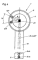
- the mouth probe 1, shown enlarged in FIG. 4, consists of a probe part 9 and a handle part 10.
- the probe part 9 comprises a rotating ring 11, which can be rotated step by step by means of a program-controlled rotary drive (not shown), in which two micro-optics of identical design in the form of a lens 12 each with a fixed, however, adjustable angular distance 13 are arranged.
- One of the lenses serves as a taking lens 12A and the other projection lens 12P.
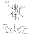
- the rotating ring 11 can be rotated step by step in each case by a defined angular amount 14 in preferably six defined positions. Six positions are selected because it is advantageous for complete three-dimensional measurement of a tooth 15 to take six partial views 16-21 from obliquely above, as shown in FIGS. 2 and 3.
- the angular amount 14 and thus the partial views to be recorded can be changed as desired using the program control.
- the angular distance 13 for adjusting the parallax angle 22 between the projection lens 12P and the taking lens 12A can also be changed.
- An optical multiplexer 23 in the probe part 9 is used for the optical coupling of both lenses 12A, 12P, each with an optical fiber cable 24A or 24P, which pass through the handle part 10 and the subsequent fiber cable connection 8.
- the fiber cable 24P connects the projection lens 12P to the video projector 2 via the multiplexer 23, while the fiber cable 24A also connects the recording lens 12A to the CCD camera 6 via the multiplexer 23.
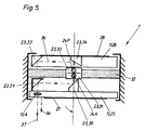
- the rotary ring 11 comprises two turntables 25, 26 which are mounted on the edge so that the area of their axis of rotation is free of mechanical fittings.
- the shooting lens 12A is arranged in the turntable 25 and the projection lens 12P, not shown here, is arranged in the turntable 26, both offset by the parallax angle 22.
- the motor drives 27, 28 for the turntables 25, 26, which are only indicated here, are program-controlled and take place either via a toothed belt system from the outside or by miniature stepper motors. Such drives are known to the person skilled in the art and need not be explained in more detail here.
- the multiplexer 23 comprises two deflection prisms / mirror arrangements, each of which is assigned to one of the turntables 25, 26.
- the arrangement assigned to the turntable 25 consists of two deflecting prisms or mirrors 29, 30, 30 mounted on the turntable 25 and a further deflecting prism or mirror, which is attached to a transparent support 32 rigidly arranged between the two turntables 25, 26.
- the arrangement associated with the turntable 26 consists of two deflection prisms or mirrors 33, 34 mounted on the turntable 26 and a further deflection prism or mirror 35 which is fastened on the transparent support 32.
- the deflection prisms or mirrors 31, 35 are arranged in the axis of rotation of the rotating ring 11 and are optically connected to the fiber cables 24A and 24P.
- the deflection prisms or mirrors 30, 34 are located in the axis of rotation of the rotary ring 11, whereby they are assigned to the deflection prisms or mirrors 31 and 35, respectively.
- the deflection prisms or mirrors 29, 33 are assigned to the objectives 12A and 12P.
- the device according to FIGS. 1, 4 and 5 works according to the triangulation and phase shift method. Both methods are known and are not explained in more detail here.
- the computer 7 digitally generates a certain, programmable stripe pattern, which is digitally stored in a projection image memory, not shown, and converted into a video signal for controlling the LCD matrix light modulator 5 in the video projector 2 via a digital / analog interface, also not shown.
- This LCD matrix light modulator 5 is irradiated with the light emitted by the incandescent lamp in order to modulate it point by point with high resolution and a large number of possible gray levels.
- the modulated light is projected via the imaging optics of the video projector 2, the optical fiber cable 24P, the deflecting prism / mirror arrangement 35, 34, 33 and the projection objective 12P onto the respectively set partial view of the tooth 15 to be measured in the form of a stripe pattern.
- the corresponding beam path is designated in FIG. 5 with the reference symbol 36.
- the recording lens 12A records the reflected or deformed light or stripe pattern, which is deformed in accordance with the topography of the respective partial view of the tooth 15 to be measured and is perceptible on the basis of the observation at the parallax angle 22, and conducts it along the beam path designated by reference number 37 in FIG. 5 the deflection prisms / mirror arrangement 29, 30, 31 and the optical fiber cable 24A of the CCD camera 6, which converts it into electrical data signals which are stored in the computer in For example, spherical coordinates, the origin of which is determined by the axis of rotation of the rotating ring 11 and is preferably inside or below the tooth, are converted and stored in a matrix memory.
- the above-described recording is repeated twice and the total measured values determined are evaluated in the computer. Subsequently, the two lenses 12A, 12P are successively transferred into the remaining five positions by correspondingly rotating the rotary ring 11 by the angular amount 14, in order to repeat the above-described recordings three times for each partial view.
- the data determined as a whole either serve to display an overall image comprising all of the partial views taken on a monitor and / or after correction by the dentist to control a grinding / milling device (not shown), for example in order to produce a tooth inlay or onlay.
- the oral probe 1 is preferably held in place by the patient's counterbite.
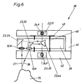
- FIG. 6 shows an oral probe 38 which differs from the oral probe 1 only in the construction details described below, but otherwise has the same function.
- the rotating ring 11 comprises a single turntable 39, which is rotatably supported by means of an axis of rotation 40 in a U-shaped arrangement 41 with a transparent leg 42 and can be driven by the drive 43.
- the objectives 12A, 12P and the associated deflecting prisms or mirrors 29 and 33 are fastened outside the axis of rotation.
- the oral probe 38 instead of the two deflecting prisms or mirrors 30, 34 according to the oral probe 1, the oral probe 38 only uses a single deflecting prism or mirror 44, which the deflecting prisms or which are also fixed in the axis of rotation, but stationary in the opposite legs of the U-shaped arrangement 41 mirrors 31, 35 are assigned.
- the mouth probe 45 shown in FIG. 7 differs from the mouth probes 1 and 38 in the construction features described below.
- the probe part 9 is designed as a non-rotatable ring 46, in which the lens arrangement used in the oral probe according to FIG. 4, consisting of the taking lens 12A and the projection lens 12P, is arranged in multiple, preferably six times, along a circular path. For reasons of space, however, only ten lenses are shown here.
- the distances between the individual lenses 12 are optionally adjustable.
- the acquisition lenses are without the interposition of a multiplexer 12A via an optical fiber cable 24A and all projection objectives 12P via an optical fiber cable 24P each connected to the CCD camera 6 or the video projector 2.
- This mouth probe 45 allows all partial views 16 to 21 to be illuminated simultaneously with the stripe pattern and to record the reflected stripe pattern.
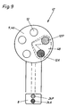
- the oral probe 47 shown in FIGS. 8 and 9 differs from the oral probe 45 in that, instead of five recording optics 12A and five associated projection optics 12P, it has only five, but preferably six or seven objectives 12, which are also at uniform intervals along a circular path are arranged on the non-rotatable ring 46.
- An optical multiplexer 48 which is only hinted at here and has basically the same structure as the prescribed multiplexer 23, connects two adjacent objectives 12 to the CCD camera 6 or the video projector 2 via the optical fiber cables 24A and 24P. In FIG. 8, the two serve the handle part 10 facing lenses as shooting lens 12A and projection lens 12P. After rotating counterclockwise by the amount of angle 14 into the position shown in FIG.
- the multiplexer 48 connects the lens used in the previous position for the projection, which is now used as the taking lens 12A, with the neighboring lens, which in this position as the projection lens 12P serves.
- the remaining lenses 12 are used in pairs to project the stripe pattern onto the remaining partial views and to record the reflected stripe patterns.
- no aids, such as calibration bodies, are required, since all partial views are recorded with great accuracy from precisely defined positions of the respective oral probe as well as the recording objectives 12A and projection objectives 12P and thus become one absolutely dimensioned 2D model can be computed computationally.
Landscapes
- Health & Medical Sciences (AREA)
- Physics & Mathematics (AREA)
- Engineering & Computer Science (AREA)
- General Physics & Mathematics (AREA)
- Animal Behavior & Ethology (AREA)
- Computer Networks & Wireless Communication (AREA)
- General Health & Medical Sciences (AREA)
- Public Health (AREA)
- Veterinary Medicine (AREA)
- Epidemiology (AREA)
- Dentistry (AREA)
- Life Sciences & Earth Sciences (AREA)
- Electromagnetism (AREA)
- Oral & Maxillofacial Surgery (AREA)
- Radar, Positioning & Navigation (AREA)
- Remote Sensing (AREA)
- Optics & Photonics (AREA)
- Dental Tools And Instruments Or Auxiliary Dental Instruments (AREA)
- Length Measuring Devices By Optical Means (AREA)
- Endoscopes (AREA)
Abstract
Claims (19)
- Dispositif pour le mesurage optique tridimensionnel de surfaces ou corps, en particulier de dents ou groupes de dents dans la cavité buccale de patients, toutes les vues partielles du corps à mesurer étant éclairées à l'aide d'au moins deux optiques associées l'une à l'autre à une distance prédéterminée dans une sonde, avec de la lumière émise par une source lumineuse, en particulier sous la forme d'un motif à bandes, et les motifs lumineux réfléchis par les vues partielles étant captés sous un angle de parallaxe correspondant à la distance entre les deux optiques et amenés à un détecteur d'image qui transforme les motifs lumineux en signaux électriques exploités dans un calculateur en vue de l'établissement d'une reproduction d'ensemble comprenant toutes les vues partielles ou représentant le corps à mesurer, caractérisé par le fait que l'éclairement des différentes vues partielles et la détection des motifs lumineux réfléchis sont effectués, soit successivement au moyen d'au moins deux optiques qui sont déplacées à l'intérieur de la sonde successivement dans des positions définies associées aux différentes vues partielles, soit simultanément ou successivement au moyen de plus de deux optiques qui sont disposées de façon fixe à l'intérieur de la sonde dans des positions définies associées aux différentes vues partielles, la sonde étant maintenue dans une position unique et donc définie en ce qui concerne l'association réciproque des différentes vues partielles.
- Procédé suivant la revendication 1, caractérisé par le fait qu'on applique le principe de la triangulation, en projetant à l'aide de l'une au moins des optiques, un motif à bandes sur les différentes vues partielles et en détectant, à l'aide de la ou de chaque autre optique et en utilisant comme base pour produire des signaux électriques, chaque motif à bandes réfléchi, déformé en fonction de la topographie de la vue partielle mesurée.
- Procédé suivant la revendication 1 ou 2, caractérisé par le fait qu'on applique le principe du déphasage en projetant un motif à bandes avec une répartition d'intensité lumineuse représentative par une courbe sinusoïde, chaque fois avec déphasage, au moins trois fois sur chaque vue partielle et en détectant le motif à bandes réfléchi.
- Dispositif pour la mise en oeuvre du procédé suivant au moins l'une des revendications 1 à 3, comprenant au moins une source lumineuse (3) pour émettre de la lumière, une sonde (1) avec au moins deux optiques (12A, 12P) associées l'une à l'autre à une distance déterminée pour éclairer toutes les vues partielles du corps à mesurer à l'aide de la lumière, en particulier sous forme d'un motif à bandes, et pour capter les motifs lumineux réfléchis par les vues partielles sous un angle de parallaxe correspondant à la distance entre les optiques, un détecteur d'image (6) pour convertir les motifs lumineux réfléchis en signaux électriques et un calculateur (7) pour exploiter les signaux électriques en vue de l'établissement d'une reproduction d'ensemble comprenant toutes les vues partielles ou représentant le corps à mesurer, caractérisé par le fait que le nombre des optiques (12A, 12P) associées par paires l'une à l'autre à une distance déterminée est égal au nombre des vues partielles (16 à 21) et leur disposition à l'intérieur de la sonde (45) est fixe et égale à la disposition réciproque des vues partielles (16 à 21), et qu'à chaque fois l'une (12P) des optiques associées par paires est reliée à la source lumineuse (3) et l'autre (12A) au détecteur d'image (6) (figure 7).
- Dispositif pour la mise en oeuvre du procédé suivant au moins l'une des revendications 1 à 3, comprenant au moins une source lumineuse (3) pour émettre de la lumière, une sonde (1) avec au moins deux optiques (12A, 12P) associées l'une à l'autre à une distance déterminée pour éclairer toutes les vues partielles du corps à mesurer à l'aide de la lumière, en particulier sous forme d'un motif à bandes, et pour capter les motifs lumineux réfléchis par les vues partielles sous un angle de parallaxe correspondant à la distance entre les optiques, un détecteur d'image (6) pour convertir les motifs lumineux réfléchis en signaux électriques et un calculateur (7) pour exploiter les signaux électriques en vue de l'établissement d'une reproduction d'ensemble comprenant toutes les vues partielles ou représentant le corps à mesurer, caractérisé par le fait que le nombre des optiques (12P, 12A) est égal au nombre des vues partielles (16 à 21) et leur disposition à l'intérieur de la sonde (47) est fixe et égale à la disposition réciproque des vues partielles (16 à 21), et qu'il est prévu un multiplexeur (48) pour le raccordement simultané par paires de chaque fois deux optiques (12P, 12A) à la source lumineuse (3) et au détecteur d'image (6) (figures 8 et 9).
- Dispositif pour la mise en oeuvre du procédé suivant au moins l'une des revendications 1 à 3, comprenant au moins une source lumineuse (3) pour émettre de la lumière, une sonde (1) avec au moins deux optiques (12A, 12P) associées l'une à l'autre à une distance déterminée pour éclairer toutes les vues partielles du corps à mesurer à l'aide de la lumière, en particulier sous forme d'un motif à bandes, et pour capter les motifs lumineux réfléchis par les vues partielles sous un angle de parallaxe correspondant à la distance entre les optiques, un détecteur d'image (6) pour convertir les motifs lumineux réfléchis en signaux électriques et un calculateur (7) pour exploiter les signaux électriques en vue de l'établissement d'une reproduction d'ensemble comprenant toutes les vues partielles ou représentant le corps à mesurer, caractérisé par le fait que les optiques (12A, 12P) au nombre de deux au moins, associées par paires l'une à l'autre à une distance déterminée, sont déplaçables par pas définis correspondant à la largeur des vues partielles (16 à 21), à l'intérieur de la sonde (1) le long d'un trajet associé à la disposition réciproque des vues partielles (16 à 21), et peuvent être reliées par un multiplexeur (23) à la source lumineuse (3) et au détecteur d'image (6) (figures 1, 4 à 6).
- Dispositif suivant au moins l'une des revendications 4, 5 ou 6, caractérisé par le fait que les optiques (12; 12A, 12P) sont disposées déplaçables le long d'un trajet circulaire ou cylindrique.
- Dispositif suivant au moins l'une des revendications 4 à 7, caractérisé par le fait que la source lumineuse (3) et le détecteur d'image (6) sont disposés à l'extérieur de la sonde (1, 38, 45, 47).
- Dispositif suivant au moins l'une des revendications 4 à 8, caractérisé par le fait qu'un modulateur de lumière (5) à matrice LCD est disposé entre la source lumineuse (3) et la sonde (1, 38, 45, 47) en vue de la production d'un motif à bandes pour la projection sur les différentes vues partielles (16 à 21).
- Dispositif suivant la revendication 8 ou 9, caractérisé par le fait que la source lumineuse (3) est disposée dans un vidéoprojecteur (2).
- Dispositif suivant au moins l'une des revendications 4 à 10, caractérisé par le fait que le multiplexeur (23, 48) est un multiplexeur optique avec un agencement de prismes de déviation et/ou de miroirs (29 à 31, 33 à 35, 44).
- Dispositif suivant la revendication 11, caractérisé par le fait que le multiplexeur optique (23, 48) est relié par des câbles de fibres optiques (24A, 24P) à la source lumineuse (3) et au détecteur d'image (6).
- Dispositif suivant au moins l'une des revendications 4 à 12, caractérisé par le fait que le détecteur d'image (6) est une caméra CCD.
- Dispositif suivant au moins l'une des revendications 4 à 13, caractérisé par le fait que la sonde est réalisée pour projeter la lumière dans et pour capter les motifs à bandes réfléchi depuis des directions opposées.
- Dispositif suivant au moins l'une des revendications 4 à 14, caractérisé par le fait que le calculateur (7) comporte des moyens pour convertir les signaux électriques en coordonnées.
- Dispositif suivant la revendication 15, caractérisé par le fait que les coordonnées sont des coordonnées sphériques.
- Dispositif suivant la revendication 15, caractérisé par le fait que les coordonnées sont des coordonnées cylindriques.
- Dispositif suivant au moins l'une des revendications 15 à 17, caractérisé par le fait que le calculateur (7) comprend une mémoire matricielle pour mémoriser les coordonnées.
- Dispositif suivant au moins l'une des revendications 4 à 18, caractérisé par le fait que la source lumineuse (3) est une source de lumière colorée ou qu'elle est suivie d'au moins un filtre de couleur (4).
Applications Claiming Priority (3)
| Application Number | Priority Date | Filing Date | Title |
|---|---|---|---|
| DE3933994A DE3933994A1 (de) | 1989-10-11 | 1989-10-11 | Optische sonde zur absoluten 3-dimensionalen vermessung von einzelzaehnen und zahngruppen in der mundhoehle |
| DE3933994 | 1989-10-11 | ||
| PCT/EP1990/001715 WO1991005520A1 (fr) | 1989-10-11 | 1990-10-11 | Procede et dispositif pour le mesurage optique tridimensionnel de corps, notamment de dents, dans la cavite buccale d'un patient |
Publications (2)
| Publication Number | Publication Date |
|---|---|
| EP0447531A1 EP0447531A1 (fr) | 1991-09-25 |
| EP0447531B1 true EP0447531B1 (fr) | 1994-04-20 |
Family
ID=6391289
Family Applications (1)
| Application Number | Title | Priority Date | Filing Date |
|---|---|---|---|
| EP90915117A Expired - Lifetime EP0447531B1 (fr) | 1989-10-11 | 1990-10-11 | Procede et dispositif pour le mesurage optique tridimensionnel de corps, notamment de dents, dans la cavite buccale d'un patient |
Country Status (4)
| Country | Link |
|---|---|
| EP (1) | EP0447531B1 (fr) |
| JP (1) | JPH04504219A (fr) |
| DE (1) | DE3933994A1 (fr) |
| WO (1) | WO1991005520A1 (fr) |
Families Citing this family (16)
| Publication number | Priority date | Publication date | Assignee | Title |
|---|---|---|---|---|
| DE4206836C2 (de) * | 1992-03-04 | 1994-07-14 | Kaltenbach & Voigt | Sonde zur optischen Vermessung von Zähnen |
| DE4213909A1 (de) * | 1992-04-28 | 1993-11-04 | Mtu Muenchen Gmbh | Vorrichtung zur vermessung von kruemmungsprofilen von kanten |
| DE4218219C2 (de) * | 1992-06-03 | 1998-05-07 | Geyer Medizin Und Fertigungste | Vorrichtung zum berührungslosen Vermessen eines schlecht zugänglichen, dreidimensionalen medizinischen oder zahntechnischen Objektes |
| DE4229466C2 (de) * | 1992-09-03 | 2001-04-26 | Kaltenbach & Voigt | Zahnvermessung ohne Kalibrationskörper |
| JPH06137841A (ja) * | 1992-10-29 | 1994-05-20 | Nikon Corp | 眼科測定装置 |
| NL9301308A (nl) * | 1993-07-26 | 1995-02-16 | Willem Frederick Van Nifterick | Werkwijze voor het vastzetten van een tandprothese op implantaten in het kaakbeen van een patiënt en middel te gebruiken daarbij. |
| DE4325542A1 (de) * | 1993-07-29 | 1995-02-02 | Fraunhofer Ges Forschung | Verfahren zur dreidimensionalen Vermessung unzugänglicher Hohlräume |
| DE19536297C2 (de) * | 1995-09-29 | 2003-10-02 | Daimler Chrysler Ag | Verfahren zur geometrischen Kalibrierung von optischen 3D-Sensoren zur dreidimensionalen Vermessung von Objekten und Vorrichtung hierzu |
| US6648640B2 (en) | 1999-11-30 | 2003-11-18 | Ora Metrix, Inc. | Interactive orthodontic care system based on intra-oral scanning of teeth |
| US7027642B2 (en) | 2000-04-28 | 2006-04-11 | Orametrix, Inc. | Methods for registration of three-dimensional frames to create three-dimensional virtual models of objects |
| ITCS20040012A1 (it) * | 2004-08-09 | 2004-11-09 | Calabrian High Tech Srl | Nuova Tecnologia per la Protesica Implantologica one-step |
| DE102007054907A1 (de) * | 2007-11-15 | 2009-05-28 | Sirona Dental Systems Gmbh | Verfahren zur optischen Vermessung von Objekten unter Verwendung eines Triangulationsverfahrens |
| DE102008054985B4 (de) | 2008-12-19 | 2012-02-02 | Sirona Dental Systems Gmbh | Verfahren und Vorrichtung zur optischen Vermessung von dreidimensionalen Objekten mittels einer dentalen 3D-Kamera unter Verwendung eines Triangulationsverfahrens |
| DE102012021185A1 (de) | 2012-10-30 | 2014-04-30 | Smart Optics Sensortechnik Gmbh | Verfahren zur optischen 3D-Vermessung von Zähnen mit verkleinerter Point-Spread-Funktion |
| DE102020127894B4 (de) | 2020-10-22 | 2022-09-22 | Smart Optics Sensortechnik Gmbh | Verfahren und Vorrichtung zur optischen dreidimensionalen Vermessung von Objekten |
| DE102020008179B4 (de) | 2020-10-22 | 2023-10-26 | Smart Optics Sensortechnik Gmbh | Verfahren und Vorrichtung zur optischen dreidimensionalen Vermessung von Objekten |
Family Cites Families (3)
| Publication number | Priority date | Publication date | Assignee | Title |
|---|---|---|---|---|
| FR2610821B1 (fr) * | 1987-02-13 | 1989-06-09 | Hennson Int | Procede de prise d'empreinte medicale et dispositif pour sa mise en oeuvre |
| GB8719951D0 (en) * | 1987-08-24 | 1987-09-30 | Lbp Partnership | Three-dimensional scanner |
| ES2033065T3 (es) * | 1988-10-18 | 1993-03-01 | Hasenclever Maschf Sms | Procedimiento y dispositivo para la determinacion de la geometria de un cuerpo. |
-
1989
- 1989-10-11 DE DE3933994A patent/DE3933994A1/de not_active Withdrawn
-
1990
- 1990-10-11 JP JP2514123A patent/JPH04504219A/ja active Pending
- 1990-10-11 WO PCT/EP1990/001715 patent/WO1991005520A1/fr active IP Right Grant
- 1990-10-11 EP EP90915117A patent/EP0447531B1/fr not_active Expired - Lifetime
Also Published As
| Publication number | Publication date |
|---|---|
| WO1991005520A1 (fr) | 1991-05-02 |
| EP0447531A1 (fr) | 1991-09-25 |
| DE3933994A1 (de) | 1991-05-08 |
| JPH04504219A (ja) | 1992-07-30 |
Similar Documents
| Publication | Publication Date | Title |
|---|---|---|
| EP0447531B1 (fr) | Procede et dispositif pour le mesurage optique tridimensionnel de corps, notamment de dents, dans la cavite buccale d'un patient | |
| DE4218219C2 (de) | Vorrichtung zum berührungslosen Vermessen eines schlecht zugänglichen, dreidimensionalen medizinischen oder zahntechnischen Objektes | |
| EP0299490B2 (fr) | Procédé pour la fabrication de dents artificielles | |
| EP0923704B1 (fr) | Procede et dispositif d'obtention d'images par moyens optiques | |
| EP2079981B1 (fr) | Dispositif et procédé pour la mesure sans contact d'un contour tridimensionnel | |
| EP3154469B1 (fr) | Dispositif de mesure et procédé pour effectuer des mesures en trois dimensions d'une cavité buccale | |
| DE10344922B4 (de) | Rundum-Scanner | |
| DE3829925A1 (de) | Optische sonde zur 3d-vermessung von zaehnen in der mundhoehle | |
| DE102011077564B4 (de) | Verfahren zur optischen dreidimensionalen Vermessung eines dentalen Objekts | |
| DE602005004332T2 (de) | Verfahren zum Bereitstellen von Daten im Zusammenhang mit der Mundhöhle | |
| EP1805480B1 (fr) | Procede et dispositif pour l`acquisition de donnees de contour et/ou des proprietes optiques d'un object tridimensionnel semi-transparent | |
| EP1757902B1 (fr) | Procédé et dispositif pour mesurer la forme d'un objet dentaire | |
| DE4229466C2 (de) | Zahnvermessung ohne Kalibrationskörper | |
| WO1991013586A1 (fr) | Procede et dispositif de mesure d'un espace, notamment de l'interieur de la bouche | |
| EP1406555B1 (fr) | Procede et dispositif pour mesurer et numeriser en trois dimensions un modele dentaire | |
| EP1105067A1 (fr) | Procede de fabrication de prothese dentaire pilote par ordinateur | |
| EP2846729B1 (fr) | Procédé de relevé d'une situation dentaire | |
| DE3810455A1 (de) | Verfahren und vorrichtung zur beruehrungsfreien raeumlichen erfassung eines unregelmaessigen koerpers | |
| DE4206836C2 (de) | Sonde zur optischen Vermessung von Zähnen | |
| DE4007957A1 (de) | Verfahren zur ausmessung eines raumes, insbesondere eines mundinnenraumes sowie vorrichtung zur durchfuehrung eines solchen verfahrens | |
| DE102011123028B3 (de) | Verfahren zur optischen dreidimensionalen Vermessung eines dentalen Objekts | |
| DE4130238A1 (de) | Verfahren zur ausmessung eines raumes, insbesondere eines mundinnenraumes, sowie vorrichtung zur durchfuehrung eines solchen verfahrens | |
| DE102011123029B3 (de) | Verfahren zur optischen dreidimensionalen Vermessung eines dentalen Objekts | |
| DE102012205800A1 (de) | Vorrichtung und verfahren zum kombinieren eines ersten und zweiten modells |
Legal Events
| Date | Code | Title | Description |
|---|---|---|---|
| PUAI | Public reference made under article 153(3) epc to a published international application that has entered the european phase |
Free format text: ORIGINAL CODE: 0009012 |
|
| AK | Designated contracting states |
Kind code of ref document: A1 Designated state(s): CH FR IT LI |
|
| 17P | Request for examination filed |
Effective date: 19910724 |
|
| 17Q | First examination report despatched |
Effective date: 19930617 |
|
| GRAA | (expected) grant |
Free format text: ORIGINAL CODE: 0009210 |
|
| AK | Designated contracting states |
Kind code of ref document: B1 Designated state(s): CH FR IT LI |
|
| ITF | It: translation for a ep patent filed |
Owner name: JACOBACCI CASETTA & PERANI S.P.A. |
|
| ET | Fr: translation filed | ||
| PGFP | Annual fee paid to national office [announced via postgrant information from national office to epo] |
Ref country code: FR Payment date: 19941017 Year of fee payment: 5 |
|
| PGFP | Annual fee paid to national office [announced via postgrant information from national office to epo] |
Ref country code: CH Payment date: 19941121 Year of fee payment: 5 |
|
| PLBE | No opposition filed within time limit |
Free format text: ORIGINAL CODE: 0009261 |
|
| STAA | Information on the status of an ep patent application or granted ep patent |
Free format text: STATUS: NO OPPOSITION FILED WITHIN TIME LIMIT |
|
| 26N | No opposition filed | ||
| PG25 | Lapsed in a contracting state [announced via postgrant information from national office to epo] |
Ref country code: LI Effective date: 19951031 Ref country code: CH Effective date: 19951031 |
|
| REG | Reference to a national code |
Ref country code: CH Ref legal event code: PL |
|
| PG25 | Lapsed in a contracting state [announced via postgrant information from national office to epo] |
Ref country code: FR Effective date: 19960628 |
|
| REG | Reference to a national code |
Ref country code: FR Ref legal event code: ST |
|
| PG25 | Lapsed in a contracting state [announced via postgrant information from national office to epo] |
Ref country code: IT Free format text: LAPSE BECAUSE OF NON-PAYMENT OF DUE FEES;WARNING: LAPSES OF ITALIAN PATENTS WITH EFFECTIVE DATE BEFORE 2007 MAY HAVE OCCURRED AT ANY TIME BEFORE 2007. THE CORRECT EFFECTIVE DATE MAY BE DIFFERENT FROM THE ONE RECORDED. Effective date: 20051011 |