EP0447516B1 - Aus bauelementen zusammensetzbares füllstandsmessgerät - Google Patents
Aus bauelementen zusammensetzbares füllstandsmessgerät Download PDFInfo
- Publication number
- EP0447516B1 EP0447516B1 EP90914507A EP90914507A EP0447516B1 EP 0447516 B1 EP0447516 B1 EP 0447516B1 EP 90914507 A EP90914507 A EP 90914507A EP 90914507 A EP90914507 A EP 90914507A EP 0447516 B1 EP0447516 B1 EP 0447516B1
- Authority
- EP
- European Patent Office
- Prior art keywords
- housing
- measuring device
- level measuring
- ultrasonic transducer
- sonic
- Prior art date
- Legal status (The legal status is an assumption and is not a legal conclusion. Google has not performed a legal analysis and makes no representation as to the accuracy of the status listed.)
- Expired - Lifetime
Links
- 238000007789 sealing Methods 0.000 claims abstract description 18
- 229910000831 Steel Inorganic materials 0.000 claims abstract description 8
- 239000010959 steel Substances 0.000 claims abstract description 8
- 239000000463 material Substances 0.000 claims description 12
- 230000008878 coupling Effects 0.000 claims description 6
- 238000010168 coupling process Methods 0.000 claims description 6
- 238000005859 coupling reaction Methods 0.000 claims description 6
- 238000001746 injection moulding Methods 0.000 claims 1
- 230000010355 oscillation Effects 0.000 claims 1
- 239000012815 thermoplastic material Substances 0.000 claims 1
- 150000001875 compounds Chemical class 0.000 abstract description 2
- 239000000725 suspension Substances 0.000 abstract 1
- 238000002604 ultrasonography Methods 0.000 description 12
- 239000012528 membrane Substances 0.000 description 11
- 238000013016 damping Methods 0.000 description 6
- 239000004033 plastic Substances 0.000 description 6
- 238000011156 evaluation Methods 0.000 description 5
- 239000002360 explosive Substances 0.000 description 5
- 230000005540 biological transmission Effects 0.000 description 3
- 238000005192 partition Methods 0.000 description 3
- 230000006978 adaptation Effects 0.000 description 2
- 238000005266 casting Methods 0.000 description 2
- 238000002347 injection Methods 0.000 description 2
- 239000007924 injection Substances 0.000 description 2
- 238000004519 manufacturing process Methods 0.000 description 2
- 230000000149 penetrating effect Effects 0.000 description 2
- 230000003068 static effect Effects 0.000 description 2
- 229920001169 thermoplastic Polymers 0.000 description 2
- 239000004416 thermosoftening plastic Substances 0.000 description 2
- FMKGJQHNYMWDFJ-CVEARBPZSA-N 2-[[4-(2,2-difluoropropoxy)pyrimidin-5-yl]methylamino]-4-[[(1R,4S)-4-hydroxy-3,3-dimethylcyclohexyl]amino]pyrimidine-5-carbonitrile Chemical compound FC(COC1=NC=NC=C1CNC1=NC=C(C(=N1)N[C@H]1CC([C@H](CC1)O)(C)C)C#N)(C)F FMKGJQHNYMWDFJ-CVEARBPZSA-N 0.000 description 1
- 239000002033 PVDF binder Substances 0.000 description 1
- 230000001154 acute effect Effects 0.000 description 1
- 238000013459 approach Methods 0.000 description 1
- 238000005452 bending Methods 0.000 description 1
- 229940127113 compound 57 Drugs 0.000 description 1
- 239000004020 conductor Substances 0.000 description 1
- 238000013461 design Methods 0.000 description 1
- 238000011161 development Methods 0.000 description 1
- 230000018109 developmental process Effects 0.000 description 1
- 231100001261 hazardous Toxicity 0.000 description 1
- -1 polybutylene terephthalate Polymers 0.000 description 1
- 229920001707 polybutylene terephthalate Polymers 0.000 description 1
- 229920002981 polyvinylidene fluoride Polymers 0.000 description 1
- 238000012545 processing Methods 0.000 description 1
- 229920002379 silicone rubber Polymers 0.000 description 1
- 125000006850 spacer group Chemical group 0.000 description 1
Images
Classifications
-
- G—PHYSICS
- G01—MEASURING; TESTING
- G01S—RADIO DIRECTION-FINDING; RADIO NAVIGATION; DETERMINING DISTANCE OR VELOCITY BY USE OF RADIO WAVES; LOCATING OR PRESENCE-DETECTING BY USE OF THE REFLECTION OR RERADIATION OF RADIO WAVES; ANALOGOUS ARRANGEMENTS USING OTHER WAVES
- G01S7/00—Details of systems according to groups G01S13/00, G01S15/00, G01S17/00
- G01S7/52—Details of systems according to groups G01S13/00, G01S15/00, G01S17/00 of systems according to group G01S15/00
- G01S7/521—Constructional features
-
- G—PHYSICS
- G01—MEASURING; TESTING
- G01F—MEASURING VOLUME, VOLUME FLOW, MASS FLOW OR LIQUID LEVEL; METERING BY VOLUME
- G01F23/00—Indicating or measuring liquid level or level of fluent solid material, e.g. indicating in terms of volume or indicating by means of an alarm
- G01F23/22—Indicating or measuring liquid level or level of fluent solid material, e.g. indicating in terms of volume or indicating by means of an alarm by measuring physical variables, other than linear dimensions, pressure or weight, dependent on the level to be measured, e.g. by difference of heat transfer of steam or water
- G01F23/28—Indicating or measuring liquid level or level of fluent solid material, e.g. indicating in terms of volume or indicating by means of an alarm by measuring physical variables, other than linear dimensions, pressure or weight, dependent on the level to be measured, e.g. by difference of heat transfer of steam or water by measuring the variations of parameters of electromagnetic or acoustic waves applied directly to the liquid or fluent solid material
- G01F23/296—Acoustic waves
- G01F23/2968—Transducers specially adapted for acoustic level indicators
-
- G—PHYSICS
- G10—MUSICAL INSTRUMENTS; ACOUSTICS
- G10K—SOUND-PRODUCING DEVICES; METHODS OR DEVICES FOR PROTECTING AGAINST, OR FOR DAMPING, NOISE OR OTHER ACOUSTIC WAVES IN GENERAL; ACOUSTICS NOT OTHERWISE PROVIDED FOR
- G10K11/00—Methods or devices for transmitting, conducting or directing sound in general; Methods or devices for protecting against, or for damping, noise or other acoustic waves in general
- G10K11/004—Mounting transducers, e.g. provided with mechanical moving or orienting device
-
- Y—GENERAL TAGGING OF NEW TECHNOLOGICAL DEVELOPMENTS; GENERAL TAGGING OF CROSS-SECTIONAL TECHNOLOGIES SPANNING OVER SEVERAL SECTIONS OF THE IPC; TECHNICAL SUBJECTS COVERED BY FORMER USPC CROSS-REFERENCE ART COLLECTIONS [XRACs] AND DIGESTS
- Y10—TECHNICAL SUBJECTS COVERED BY FORMER USPC
- Y10S—TECHNICAL SUBJECTS COVERED BY FORMER USPC CROSS-REFERENCE ART COLLECTIONS [XRACs] AND DIGESTS
- Y10S367/00—Communications, electrical: acoustic wave systems and devices
- Y10S367/908—Material level detection, e.g. liquid level
Definitions
- the invention relates to a fill level measuring device for measuring the fill level in a container with a sound or ultrasound transducer, which directs a transmission pulse to the filling material in the container and receives the echo signal reflected on the filling material, and with an electronic circuit which connects the sound or ultrasound transducer Vibrations are excited and the received echo signal is converted into an electrical signal and transmitted to an evaluation device and receives the energy required for the function of the level measuring device from the evaluation device, the sound or ultrasound converter being a first functional unit enclosed by a housing and the electronic circuit being one of one Form housing enclosed second functional unit.
- the housing enclosing the sound or ultrasonic transducer is a cup-shaped one Plastic part which is attached by means of a molded ring approach on the surface of a flange facing the container, so that it encloses the sound or ultrasonic transducer on the container side.
- the housing enclosing the electronic circuit is fastened on the side of the flange facing away from the container, and the electronic circuit is connected to the sound or ultrasound transducer by a line which is passed through the flange.
- the flange is connected to a counter flange which surrounds a circular cylindrical container opening through which the transducer housing then projects into the interior of the container.
- the converter housing is a simple and cheap plastic part, but due to the exposed position of the vulnerable converter housing, the level meter does not meet the requirements for use in potentially explosive atmospheres.
- the flange which on one side carries the transducer housing with the sound or ultrasound transducer and on the other side the housing with the electronic circuit, is an integral part of the level measuring device.
- a level measuring device known from document GB-A-2 195 445 is formed and assembled, but with the difference that the sound or ultrasound transducer is arranged in a circular cylindrical recess formed in the flange, the bottom of which is the membrane of the sound or Ultrasonic transducer forms.
- the membrane is formed in one piece with the flange, so that a homogeneous continuous surface faces the interior of the container.
- the flange forms an integral part of the level measuring device, the manufacture of which is very complex because of the precision processing of the metallic flange required.
- the same level measuring device could also be used in non-hazardous areas, the considerable manufacturing costs would not be justified there.
- the object of the invention is to provide a fill level measuring device of the type specified at the outset, which is inexpensive to produce and is suitable for different applications, in particular also in aggressive media or in potentially explosive areas.
- the level measuring device in contrast to the level measuring devices of the prior art, in which the mounting flange is an essential integrated component of the device, the level measuring device according to the invention consists of two functional units, the housing of which is formed independently of a mounting flange and is directly detachably connected to one another.
- the Level meter can therefore be completely assembled without the mounting flange and optionally attached to the container in other ways than by flange mounting.
- the housings can be manufactured in a simple and inexpensive manner, preferably as plastic injection molded parts. With a suitable choice of plastic, the level measuring device is suitable for use with aggressive media.
- the sound or ultrasound transducer is protected in the trough formed in the housing, which at the same time results in good structure-borne noise decoupling between the sound or ultrasound transducer and the outer part of the transducer housing which is in contact with the mounting flange and the container wall.
- the steel plate which is attached to the side of the acoustic or ultrasonic transducer facing away from the filling material, prevents excessive deformation of the transducer membrane in the event of a sudden pressure increase in the container.
- the level meter is also suitable for use in potentially explosive areas.
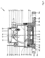
- a level measuring device 1 which has a housing 2, a hood 4 and a cover 6.
- a transmission and reception converter 21 is accommodated in the interior of the housing 2. It generates a transmission pulse directed at the surface of the medium to be measured and receives the echo reflected from the surface of the medium.
- the transmitting and receiving transducer 21 consists in a known manner of a piezoceramic element 22, an adaptation layer 23, a damping layer 24 and a membrane 25.
- the layers 23, 24 consist of a silicone elastomer.
- the piezoceramic element 22 is connected to the membrane 25 via spacers 26. To protect the membrane 25, it is set back in a known manner in relation to the end of the housing 2 facing the filling material.
- the transducer 21 is not connected directly to the wall of the housing 2, but rather is arranged within a cylindrical depression 27 which extends axially from the diaphragm 25 and forms a Position coaxial to the axis of symmetry of the housing 2.
- the trough 27 and the housing 2 are connected to one another only via a short cylindrical section 28 and an annular cylindrical zone 29.
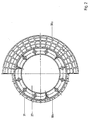
- cylindrical supports 31 are arranged in the interior of the housing 2 in the interior of the housing 2 .
- the cylindrical supports 31 are integrally formed on the ring zone 29 and extend at the same distance from one another, arranged on a bolt circle, along the inner lateral surface of the housing 2. They assume such a position that they are not spatially connected to the outer surface of the housing 2 stand (Fig. 2). At her facing away from the ring zone 29 At the end, the cylindrical supports 31 are penetrated by an internal thread.
- the interior of the housing 2 is almost completely filled by the damping layer 24.
- the top of the damping layer 24 assumes a position that coincides approximately with the end of the supports 31. If the level measuring device 1 is to be inserted into a container whose internal pressure is above that of the normal atmosphere, the membrane 25 is also exposed to this pressure.
- the transmitting and receiving transducer 21 is closed off by a steel plate 32.
- the steel plate 32 lies on the damping layer 24 and is fastened to the cylindrical supports 31 by means of screw connections 33. The steel plate 32 then absorbs the internal pressure of the container via the membrane 25 and also prevents vibrational energy of the piezoceramic element 22 from being radiated through the damping layer 24, towards the side facing away from the membrane 25.
- the trough 27 extends spatially in such a way that, depending on the application, various types of piezoceramic elements, surrounded by an adaptation and damping layer, find space.
- the housing 2 is in a known manner as a molded part made of a thermoplastic and chemically resistant plastic, for. B. made of polyvinylidene fluoride. In order to be able to use such a plastic part in an explosive atmosphere, measures must be taken to prevent static charging.
- a sealing strip 30a or 30b is arranged on the housing 2 on the side facing the filling material. The sealing strip 30a or 30b has the task of closing the opening of a wall enclosing the filling material, through which the level measuring device 1 communicates with the filling material, including an annular flat seal, when the level measuring device 1 is attached to the wall.
- the design of the sealing strip 30a which extends to the right of the outer surface of the housing 2, is different from that of the sealing strip 30b, which extends to the left of the housing 2.
- the housing shapes are produced by an insert which is introduced into the injection mold in a known manner.
- the sealing strip 30a extends radially outward from the lateral surface of the housing 2.
- the sealing strip 30a is designed so that it can be encompassed by the shoulder 35a of a coupling flange 34a. It is designed in such a way that it can be encompassed by any flanges that are manufactured according to domestic and foreign flange standards.
- the sealing strip 30a is intended for large nominal widths and is formed from two separate annular sealing surfaces which extend outside the outer surface of the housing 2 and are simultaneously encompassed by the shoulder 35a of the flange 34a.
- the sealing strip 30b is in the Arranged inside the outer surface of the housing 2 and formed by a closed, annular sealing surface.
- one version of the housing 2 with the sealing strip 30b is sufficient.
- the sealing strips 30a, 30b are interrupted by partitions and cutouts, so that only small, continuous surfaces preventing a charge are present.
- Fig. 2 it is shown how these molded parts are designed by inserting ribs and breakouts.
- the hood 4 is also made as a molded part from a thermoplastic, advantageously from a polybutylene terephthalate.
- a circuit board 41 is arranged in its interior. On the circuit board (not shown) the electronic components are arranged, which form the electronic circuit of the level measuring device 1. The electronic parts are electrically connected to one another by conductor tracks (not shown). Furthermore, the printed circuit board 41 is connected by a connecting line 42 to terminals 43 which, arranged on a base 44, project into the connection space 45.
- the base 44 is designed in such a way that the terminal strip of the connecting terminal 43 is at an acute angle to the axis of symmetry of the hood 4, as a result of which the connection of the electrical line in the connecting space 45 is made considerably easier.
- connection cable 46 is connected, which connects the level measuring device 1 with an evaluation device and via which the measured values determined by the level measuring device 1 are transmitted to the evaluation device and also the energy necessary for the function of the level measuring device 1 is transmitted from the evaluation device.
- a PG screw connection 47 the connection cable 46 is inserted into the connection space 45 and the implementation is completed.
- connection space 45 also has a ground connection terminal 48. This is designed as a screw connection penetrating the intermediate wall 49.
- the intermediate wall 49 also has a further opening 50, which serves to lead the electrical connecting line 42 from the printed circuit board 41 to the connecting terminals 43.
- a screw connection 51 penetrates a collar formed on the hood 4.
- the tight connection between the housing 2 and the hood 4 is achieved in that the housing 2 has an annular web 36 and on the hood 4 a collar 52 revolves around the outer surface, which on the housing 2 facing side is pierced by a groove which surrounds the web 36.
- connection space 45 is closed on the side facing away from the membrane 25 by means of the cover 6.
- the cover 6 is supported on a collar 61 which lies opposite the annular end face 53 of the hood 4.
- a circumferential groove in which an annular seal 63 is arranged, is formed on the cylindrical region 62 and breaks through the lateral surface.
- the ring-shaped seal 63 can be formed from a commercially available O-ring.
- the hood 4 is designed so that the fill level measuring device 1 can in turn be designed in two different embodiments. For use in a normal atmosphere, the hood 4 is designed as it has just been shown. For use in an explosive medium, however, it is necessary to hermetically seal the live parts of the circuit board 41 from the outside world.
- a commercially available casting compound 57 is filled with the cover 6 open through the recess 50 into the interior of the hood 4 until the interior is completely filled up to the partition 49 and the electrical components including the printed circuit board 41 are surrounded by the casting compound.
- a bushes 54 are formed above the partition 49, which are diametrically opposite. For the sake of better illustration, only one of the two bushes 54 is shown in FIG. 1.
- the bushes 54 are penetrated by a thread and, together with a screw 55, form a screw connection through which a bracket 56 is fastened to the hood 4. With the aid of the bracket 56, it is possible to suspend the level sensor 1 deflected in all directions on the container wall or the ceiling of a container or over an open channel, the flange connection 34a or 34b naturally being omitted.
Landscapes
- Physics & Mathematics (AREA)
- Engineering & Computer Science (AREA)
- Acoustics & Sound (AREA)
- General Physics & Mathematics (AREA)
- Electromagnetism (AREA)
- Thermal Sciences (AREA)
- Fluid Mechanics (AREA)
- Computer Networks & Wireless Communication (AREA)
- Radar, Positioning & Navigation (AREA)
- Remote Sensing (AREA)
- Multimedia (AREA)
- Measurement Of Levels Of Liquids Or Fluent Solid Materials (AREA)
Applications Claiming Priority (3)
| Application Number | Priority Date | Filing Date | Title |
|---|---|---|---|
| DE3933474 | 1989-10-06 | ||
| DE3933474A DE3933474C2 (de) | 1989-10-06 | 1989-10-06 | Füllstandsmeßgerät |
| PCT/DE1990/000761 WO1991005226A1 (de) | 1989-10-06 | 1990-10-05 | Aus bauelementen zusammensetzbares füllstandsmessgerät |
Publications (2)
| Publication Number | Publication Date |
|---|---|
| EP0447516A1 EP0447516A1 (de) | 1991-09-25 |
| EP0447516B1 true EP0447516B1 (de) | 1995-08-23 |
Family
ID=6390998
Family Applications (1)
| Application Number | Title | Priority Date | Filing Date |
|---|---|---|---|
| EP90914507A Expired - Lifetime EP0447516B1 (de) | 1989-10-06 | 1990-10-05 | Aus bauelementen zusammensetzbares füllstandsmessgerät |
Country Status (8)
| Country | Link |
|---|---|
| US (1) | US5363341A (ja) |
| EP (1) | EP0447516B1 (ja) |
| JP (1) | JPH0676906B2 (ja) |
| AU (1) | AU633632B2 (ja) |
| CA (1) | CA2042383C (ja) |
| DE (2) | DE3933474C2 (ja) |
| HU (1) | HU207159B (ja) |
| WO (1) | WO1991005226A1 (ja) |
Cited By (1)
| Publication number | Priority date | Publication date | Assignee | Title |
|---|---|---|---|---|
| EP4418008A3 (en) * | 2023-02-20 | 2024-12-18 | Autonics Corporation | Sensor apparatus |
Families Citing this family (29)
| Publication number | Priority date | Publication date | Assignee | Title |
|---|---|---|---|---|
| DE4311963C2 (de) * | 1993-04-10 | 1996-10-24 | Endress Hauser Gmbh Co | Füllstandsmeßgerät |
| US5550790A (en) * | 1995-02-10 | 1996-08-27 | Kistler-Morse Corporation | Acoustic transducer for level measurement in corrosive chemical environments |
| EP0766071B1 (de) * | 1995-09-28 | 2002-04-10 | Endress + Hauser Gmbh + Co. | Ultraschallwandler |
| DE19538680C2 (de) * | 1995-10-17 | 1998-10-08 | Endress Hauser Gmbh Co | Anordnung zur Überwachung eines vorbestimmten Füllstands einer Flüssigkeit in einem Behälter |
| DE19538677C2 (de) * | 1995-10-17 | 1998-12-17 | Endress Hauser Gmbh Co | Anordnung zur Überwachung eines vorbestimmten Füllstands einer Flüssigkeit in einem Behälter |
| DE19538696C2 (de) * | 1995-10-17 | 1997-09-25 | Endress Hauser Gmbh Co | Anordnung zur Überwachung eines vorbestimmten Füllstands einer Flüssigkeit in einem Behälter |
| US5962952A (en) * | 1995-11-03 | 1999-10-05 | Coherent Technologies, Inc. | Ultrasonic transducer |
| US5598845A (en) * | 1995-11-16 | 1997-02-04 | Stellartech Research Corporation | Ultrasound transducer device for continuous imaging of the heart and other body parts |
| US5822274A (en) * | 1996-04-12 | 1998-10-13 | Flowline Inc. | Method and apparatus for acoustically measuring the level of liquid in a tank |
| US5944317A (en) * | 1997-07-07 | 1999-08-31 | Rohrbaugh; George Wilson | Shock wave scoring apparatus employing dual concentric curved rod sensors |
| DE19755729A1 (de) * | 1997-12-15 | 1999-06-17 | Bosch Gmbh Robert | Ultraschallsensor |
| DK0945714T3 (da) * | 1998-03-17 | 2011-01-31 | Endress & Hauser Deutschland Ag & Co Kg | Elektronisk udstyr til brug i eksplosionsudsatte områder |
| GB9910130D0 (en) * | 1999-04-30 | 1999-06-30 | Motosonics Ltd | Sensor apparatus |
| DK200101780A (da) * | 2001-11-30 | 2002-11-27 | Danfoss As | Ultralydstransducer |
| DE10250065A1 (de) * | 2002-10-25 | 2004-05-06 | Endress + Hauser Flowtec Ag, Reinach | Prozeß-Meßgerät |
| US7098669B2 (en) | 2003-10-01 | 2006-08-29 | Flowline, Inc. | Depth determining system |
| US7363811B2 (en) * | 2005-04-07 | 2008-04-29 | Endress + Hauser Flowtec Ag | Measurement pickup |
| DE102007021099A1 (de) | 2007-05-03 | 2008-11-13 | Endress + Hauser (Deutschland) Ag + Co. Kg | Verfahren zum Inbetriebnehmen und/oder Rekonfigurieren eines programmierbaren Feldmeßgeräts |
| DE102007058608A1 (de) | 2007-12-04 | 2009-06-10 | Endress + Hauser Flowtec Ag | Elektrisches Gerät |
| DE102008022373A1 (de) | 2008-05-06 | 2009-11-12 | Endress + Hauser Flowtec Ag | Meßgerät sowie Verfahren zum Überwachen eines Meßgeräts |
| JP5075171B2 (ja) * | 2009-09-02 | 2012-11-14 | パナソニック株式会社 | 超音波センサ |
| CN102859852B (zh) | 2010-04-19 | 2015-11-25 | 恩德斯+豪斯流量技术股份有限公司 | 测量变换器的驱动电路及由该驱动电路形成的测量系统 |
| DE202010006553U1 (de) | 2010-05-06 | 2011-10-05 | Endress + Hauser Flowtec Ag | Elektronisches Meßgerät mit einem Optokoppler |
| DE102010030924A1 (de) | 2010-06-21 | 2011-12-22 | Endress + Hauser Flowtec Ag | Elektronik-Gehäuse für ein elektronisches Gerät bzw. damit gebildetes Gerät |
| DE102011076838A1 (de) | 2011-05-31 | 2012-12-06 | Endress + Hauser Flowtec Ag | Meßgerät-Elektronik für ein Meßgerät-Gerät sowie damit gebildetes Meßgerät-Gerät |
| US11566932B2 (en) * | 2014-07-09 | 2023-01-31 | Husky Corporation | Sonic monitor system for a tank |
| DE102016114860A1 (de) | 2016-08-10 | 2018-02-15 | Endress + Hauser Flowtec Ag | Treiberschaltung sowie damit gebildete Umformer-Elektronik bzw. damit gebildetes Meßsystem |
| EP4083583A1 (en) | 2021-04-30 | 2022-11-02 | Tekelek Group Holdings Limited | An ultrasonic distance sensor and a method for protecting an ultrasonic transducer in an ultrasonic distance sensor |
| DE102021132304A1 (de) * | 2021-12-08 | 2023-06-15 | Endress+Hauser SE+Co. KG | Feldgerät der Prozess- und Automatisierungstechnik |
Family Cites Families (9)
| Publication number | Priority date | Publication date | Assignee | Title |
|---|---|---|---|---|
| JPS563429B2 (ja) * | 1973-11-01 | 1981-01-24 | ||
| US3910116A (en) * | 1973-12-07 | 1975-10-07 | Rexnord Inc | Transducer positioning means for fluid level monitoring |
| US4183007A (en) * | 1978-02-22 | 1980-01-08 | Fischer & Porter Company | Ultrasonic transceiver |
| DK147718C (da) * | 1982-07-21 | 1985-05-13 | Nils Jensen | Ultralydapparat til niveaumaaling i tanke eller lignende forraadsrum |
| DE8332045U1 (de) * | 1983-11-08 | 1984-02-23 | Endress U. Hauser Gmbh U. Co, 7867 Maulburg | Ultraschallsensor eines Füllstandsmeßgerätes |
| DE3416254C2 (de) * | 1984-05-02 | 1986-06-19 | VEGA Grieshaber GmbH & Co, 7620 Wolfach | Vorrichtung zur Feststellung eines bestimmten Füllstandes eines Füllgutes in einem Behälter |
| DE3633047A1 (de) * | 1986-09-29 | 1988-04-07 | Endress Hauser Gmbh Co | Fuellstandmessgeraet zur messung des fuellstandes von explosiblen oder aggresiven medien in einem behaelter |
| DE8630763U1 (de) * | 1986-11-17 | 1987-03-12 | Endress U. Hauser Gmbh U. Co, 7867 Maulburg | Schall- oder Ultraschallsensor |
| GB8709903D0 (en) * | 1987-04-27 | 1987-06-03 | Gec Avionics | Sensor apparatus |
-
1989
- 1989-10-06 DE DE3933474A patent/DE3933474C2/de not_active Expired - Fee Related
-
1990
- 1990-10-05 AU AU64406/90A patent/AU633632B2/en not_active Ceased
- 1990-10-05 JP JP2513532A patent/JPH0676906B2/ja not_active Expired - Fee Related
- 1990-10-05 US US07/689,830 patent/US5363341A/en not_active Expired - Fee Related
- 1990-10-05 CA CA002042383A patent/CA2042383C/en not_active Expired - Fee Related
- 1990-10-05 WO PCT/DE1990/000761 patent/WO1991005226A1/de active IP Right Grant
- 1990-10-05 EP EP90914507A patent/EP0447516B1/de not_active Expired - Lifetime
- 1990-10-05 DE DE59009559T patent/DE59009559D1/de not_active Expired - Fee Related
- 1990-10-05 HU HU907908A patent/HU207159B/hu unknown
Cited By (1)
| Publication number | Priority date | Publication date | Assignee | Title |
|---|---|---|---|---|
| EP4418008A3 (en) * | 2023-02-20 | 2024-12-18 | Autonics Corporation | Sensor apparatus |
Also Published As
| Publication number | Publication date |
|---|---|
| AU6440690A (en) | 1991-04-28 |
| DE3933474C2 (de) | 1994-01-27 |
| DE3933474A1 (de) | 1991-04-25 |
| HUT57895A (en) | 1991-12-30 |
| JPH03505133A (ja) | 1991-11-07 |
| AU633632B2 (en) | 1993-02-04 |
| EP0447516A1 (de) | 1991-09-25 |
| WO1991005226A1 (de) | 1991-04-18 |
| HU207159B (en) | 1993-03-01 |
| DE59009559D1 (de) | 1995-09-28 |
| US5363341A (en) | 1994-11-08 |
| CA2042383C (en) | 1996-03-19 |
| CA2042383A1 (en) | 1991-04-07 |
| JPH0676906B2 (ja) | 1994-09-28 |
| HU907908D0 (en) | 1991-08-28 |
Similar Documents
| Publication | Publication Date | Title |
|---|---|---|
| EP0447516B1 (de) | Aus bauelementen zusammensetzbares füllstandsmessgerät | |
| EP0984248B1 (de) | Messaufnehmer | |
| DE3633047C2 (ja) | ||
| EP0769684B1 (de) | Anordnung zur Überwachung eines vorbestimmten Füllstands einer Flüsssigkeit in einem Behälter | |
| DE3539555A1 (de) | Mikrowellen-fuellstandsmesssystem | |
| DE19649679B4 (de) | Schwingungserfassungssensor | |
| EP0769683A2 (de) | Anordnung zur Überwachung eines vorbestimmten Füllstands einer Flüssigkeit in einem Behälter | |
| EP3055858B1 (de) | Ultraschallsensor | |
| DE102012108254A1 (de) | Ultraschall-Wandler und Verfahren zur Herstellung eines Ultraschall-Wandlers | |
| EP3588017A1 (de) | Ultraschallmessvorrichtung | |
| WO2000079513A1 (de) | Dämpfende halterung für das gehäuse eines ultraschallwandlers und verfahren zur herstellung | |
| DE102016224083A1 (de) | Elektrische Baugruppe | |
| DE19755729A1 (de) | Ultraschallsensor | |
| EP3444573A1 (de) | Schallkopf für einen durchflussmesser mit ausziehmitteln | |
| DE4328366C3 (de) | Näherungsschalter | |
| EP3168579A1 (de) | Hornantenne | |
| EP2116474A1 (de) | Ultraschallsensor | |
| DE102020200771B4 (de) | Fluidsensorvorrichtung zum Erfassen des Füllstands und/oder der Qualität eines Fluids und Verfahren zum Herstellen derselben | |
| DE4126399C2 (ja) | ||
| EP3341931B1 (de) | Akustischer sensor mit einem gehäuse und einem an diesem gehäuse angeordneten membranelement | |
| DE102022130025B3 (de) | Ultraschall-Wandler | |
| DE102022005133B4 (de) | Ultraschall-Wandler | |
| DE102022005131B4 (de) | Ultraschall-Wandler | |
| DE4138528C1 (en) | Ultrasonic transducer e.g. for level indicator - has diaphragm held between seals and flange in direct contact with attachment surface or via spacer | |
| LU500838B1 (de) | Schallwandlervorrichtung |
Legal Events
| Date | Code | Title | Description |
|---|---|---|---|
| PUAI | Public reference made under article 153(3) epc to a published international application that has entered the european phase |
Free format text: ORIGINAL CODE: 0009012 |
|
| 17P | Request for examination filed |
Effective date: 19910524 |
|
| AK | Designated contracting states |
Kind code of ref document: A1 Designated state(s): CH DE FR GB IT LI SE |
|
| 17Q | First examination report despatched |
Effective date: 19940105 |
|
| GRAA | (expected) grant |
Free format text: ORIGINAL CODE: 0009210 |
|
| ITF | It: translation for a ep patent filed | ||
| AK | Designated contracting states |
Kind code of ref document: B1 Designated state(s): CH DE FR GB IT LI SE |
|
| REF | Corresponds to: |
Ref document number: 59009559 Country of ref document: DE Date of ref document: 19950928 |
|
| ET | Fr: translation filed | ||
| GBT | Gb: translation of ep patent filed (gb section 77(6)(a)/1977) |
Effective date: 19951130 |
|
| PLBE | No opposition filed within time limit |
Free format text: ORIGINAL CODE: 0009261 |
|
| STAA | Information on the status of an ep patent application or granted ep patent |
Free format text: STATUS: NO OPPOSITION FILED WITHIN TIME LIMIT |
|
| 26N | No opposition filed | ||
| PGFP | Annual fee paid to national office [announced via postgrant information from national office to epo] |
Ref country code: CH Payment date: 19990915 Year of fee payment: 10 |
|
| PGFP | Annual fee paid to national office [announced via postgrant information from national office to epo] |
Ref country code: SE Payment date: 19990920 Year of fee payment: 10 |
|
| PG25 | Lapsed in a contracting state [announced via postgrant information from national office to epo] |
Ref country code: SE Free format text: THE PATENT HAS BEEN ANNULLED BY A DECISION OF A NATIONAL AUTHORITY Effective date: 20001030 |
|
| PG25 | Lapsed in a contracting state [announced via postgrant information from national office to epo] |
Ref country code: LI Free format text: LAPSE BECAUSE OF NON-PAYMENT OF DUE FEES Effective date: 20001031 Ref country code: CH Free format text: LAPSE BECAUSE OF NON-PAYMENT OF DUE FEES Effective date: 20001031 |
|
| REG | Reference to a national code |
Ref country code: CH Ref legal event code: PL |
|
| EUG | Se: european patent has lapsed |
Ref document number: 90914507.0 |
|
| REG | Reference to a national code |
Ref country code: GB Ref legal event code: IF02 |
|
| PGFP | Annual fee paid to national office [announced via postgrant information from national office to epo] |
Ref country code: GB Payment date: 20020925 Year of fee payment: 13 |
|
| PGFP | Annual fee paid to national office [announced via postgrant information from national office to epo] |
Ref country code: FR Payment date: 20021009 Year of fee payment: 13 |
|
| PGFP | Annual fee paid to national office [announced via postgrant information from national office to epo] |
Ref country code: DE Payment date: 20021017 Year of fee payment: 13 |
|
| PG25 | Lapsed in a contracting state [announced via postgrant information from national office to epo] |
Ref country code: GB Free format text: LAPSE BECAUSE OF NON-PAYMENT OF DUE FEES Effective date: 20031005 |
|
| PG25 | Lapsed in a contracting state [announced via postgrant information from national office to epo] |
Ref country code: DE Free format text: LAPSE BECAUSE OF NON-PAYMENT OF DUE FEES Effective date: 20040501 |
|
| GBPC | Gb: european patent ceased through non-payment of renewal fee |
Effective date: 20031005 |
|
| PG25 | Lapsed in a contracting state [announced via postgrant information from national office to epo] |
Ref country code: FR Free format text: LAPSE BECAUSE OF NON-PAYMENT OF DUE FEES Effective date: 20040630 |
|
| REG | Reference to a national code |
Ref country code: FR Ref legal event code: ST |
|
| PG25 | Lapsed in a contracting state [announced via postgrant information from national office to epo] |
Ref country code: IT Free format text: LAPSE BECAUSE OF NON-PAYMENT OF DUE FEES Effective date: 20051005 |