EP0447516B1 - Aus bauelementen zusammensetzbares füllstandsmessgerät - Google Patents
Aus bauelementen zusammensetzbares füllstandsmessgerät Download PDFInfo
- Publication number
- EP0447516B1 EP0447516B1 EP90914507A EP90914507A EP0447516B1 EP 0447516 B1 EP0447516 B1 EP 0447516B1 EP 90914507 A EP90914507 A EP 90914507A EP 90914507 A EP90914507 A EP 90914507A EP 0447516 B1 EP0447516 B1 EP 0447516B1
- Authority
- EP
- European Patent Office
- Prior art keywords
- housing
- measuring device
- level measuring
- ultrasonic transducer
- sonic
- Prior art date
- Legal status (The legal status is an assumption and is not a legal conclusion. Google has not performed a legal analysis and makes no representation as to the accuracy of the status listed.)
- Expired - Lifetime
Links
- 238000007789 sealing Methods 0.000 claims abstract description 18
- 229910000831 Steel Inorganic materials 0.000 claims abstract description 8
- 239000010959 steel Substances 0.000 claims abstract description 8
- 239000000463 material Substances 0.000 claims description 12
- 230000008878 coupling Effects 0.000 claims description 6
- 238000010168 coupling process Methods 0.000 claims description 6
- 238000005859 coupling reaction Methods 0.000 claims description 6
- 238000001746 injection moulding Methods 0.000 claims 1
- 230000010355 oscillation Effects 0.000 claims 1
- 239000012815 thermoplastic material Substances 0.000 claims 1
- 150000001875 compounds Chemical class 0.000 abstract description 2
- 239000000725 suspension Substances 0.000 abstract 1
- 238000002604 ultrasonography Methods 0.000 description 12
- 239000012528 membrane Substances 0.000 description 11
- 238000013016 damping Methods 0.000 description 6
- 239000004033 plastic Substances 0.000 description 6
- 238000011156 evaluation Methods 0.000 description 5
- 239000002360 explosive Substances 0.000 description 5
- 230000005540 biological transmission Effects 0.000 description 3
- 238000005192 partition Methods 0.000 description 3
- 230000006978 adaptation Effects 0.000 description 2
- 238000005266 casting Methods 0.000 description 2
- 238000002347 injection Methods 0.000 description 2
- 239000007924 injection Substances 0.000 description 2
- 238000004519 manufacturing process Methods 0.000 description 2
- 230000000149 penetrating effect Effects 0.000 description 2
- 230000003068 static effect Effects 0.000 description 2
- 229920001169 thermoplastic Polymers 0.000 description 2
- 239000004416 thermosoftening plastic Substances 0.000 description 2
- FMKGJQHNYMWDFJ-CVEARBPZSA-N 2-[[4-(2,2-difluoropropoxy)pyrimidin-5-yl]methylamino]-4-[[(1R,4S)-4-hydroxy-3,3-dimethylcyclohexyl]amino]pyrimidine-5-carbonitrile Chemical compound FC(COC1=NC=NC=C1CNC1=NC=C(C(=N1)N[C@H]1CC([C@H](CC1)O)(C)C)C#N)(C)F FMKGJQHNYMWDFJ-CVEARBPZSA-N 0.000 description 1
- 239000002033 PVDF binder Substances 0.000 description 1
- 230000001154 acute effect Effects 0.000 description 1
- 238000013459 approach Methods 0.000 description 1
- 238000005452 bending Methods 0.000 description 1
- 229940127113 compound 57 Drugs 0.000 description 1
- 239000004020 conductor Substances 0.000 description 1
- 238000013461 design Methods 0.000 description 1
- 238000011161 development Methods 0.000 description 1
- 230000018109 developmental process Effects 0.000 description 1
- 231100001261 hazardous Toxicity 0.000 description 1
- -1 polybutylene terephthalate Polymers 0.000 description 1
- 229920001707 polybutylene terephthalate Polymers 0.000 description 1
- 229920002981 polyvinylidene fluoride Polymers 0.000 description 1
- 238000012545 processing Methods 0.000 description 1
- 229920002379 silicone rubber Polymers 0.000 description 1
- 125000006850 spacer group Chemical group 0.000 description 1
Images
Classifications
-
- G—PHYSICS
- G01—MEASURING; TESTING
- G01S—RADIO DIRECTION-FINDING; RADIO NAVIGATION; DETERMINING DISTANCE OR VELOCITY BY USE OF RADIO WAVES; LOCATING OR PRESENCE-DETECTING BY USE OF THE REFLECTION OR RERADIATION OF RADIO WAVES; ANALOGOUS ARRANGEMENTS USING OTHER WAVES
- G01S7/00—Details of systems according to groups G01S13/00, G01S15/00, G01S17/00
- G01S7/52—Details of systems according to groups G01S13/00, G01S15/00, G01S17/00 of systems according to group G01S15/00
- G01S7/521—Constructional features
-
- G—PHYSICS
- G01—MEASURING; TESTING
- G01F—MEASURING VOLUME, VOLUME FLOW, MASS FLOW OR LIQUID LEVEL; METERING BY VOLUME
- G01F23/00—Indicating or measuring liquid level or level of fluent solid material, e.g. indicating in terms of volume or indicating by means of an alarm
- G01F23/22—Indicating or measuring liquid level or level of fluent solid material, e.g. indicating in terms of volume or indicating by means of an alarm by measuring physical variables, other than linear dimensions, pressure or weight, dependent on the level to be measured, e.g. by difference of heat transfer of steam or water
- G01F23/28—Indicating or measuring liquid level or level of fluent solid material, e.g. indicating in terms of volume or indicating by means of an alarm by measuring physical variables, other than linear dimensions, pressure or weight, dependent on the level to be measured, e.g. by difference of heat transfer of steam or water by measuring the variations of parameters of electromagnetic or acoustic waves applied directly to the liquid or fluent solid material
- G01F23/296—Acoustic waves
- G01F23/2968—Transducers specially adapted for acoustic level indicators
-
- G—PHYSICS
- G10—MUSICAL INSTRUMENTS; ACOUSTICS
- G10K—SOUND-PRODUCING DEVICES; METHODS OR DEVICES FOR PROTECTING AGAINST, OR FOR DAMPING, NOISE OR OTHER ACOUSTIC WAVES IN GENERAL; ACOUSTICS NOT OTHERWISE PROVIDED FOR
- G10K11/00—Methods or devices for transmitting, conducting or directing sound in general; Methods or devices for protecting against, or for damping, noise or other acoustic waves in general
- G10K11/004—Mounting transducers, e.g. provided with mechanical moving or orienting device
-
- Y—GENERAL TAGGING OF NEW TECHNOLOGICAL DEVELOPMENTS; GENERAL TAGGING OF CROSS-SECTIONAL TECHNOLOGIES SPANNING OVER SEVERAL SECTIONS OF THE IPC; TECHNICAL SUBJECTS COVERED BY FORMER USPC CROSS-REFERENCE ART COLLECTIONS [XRACs] AND DIGESTS
- Y10—TECHNICAL SUBJECTS COVERED BY FORMER USPC
- Y10S—TECHNICAL SUBJECTS COVERED BY FORMER USPC CROSS-REFERENCE ART COLLECTIONS [XRACs] AND DIGESTS
- Y10S367/00—Communications, electrical: acoustic wave systems and devices
- Y10S367/908—Material level detection, e.g. liquid level
Definitions
- the invention relates to a fill level measuring device for measuring the fill level in a container with a sound or ultrasound transducer, which directs a transmission pulse to the filling material in the container and receives the echo signal reflected on the filling material, and with an electronic circuit which connects the sound or ultrasound transducer Vibrations are excited and the received echo signal is converted into an electrical signal and transmitted to an evaluation device and receives the energy required for the function of the level measuring device from the evaluation device, the sound or ultrasound converter being a first functional unit enclosed by a housing and the electronic circuit being one of one Form housing enclosed second functional unit.
- the housing enclosing the sound or ultrasonic transducer is a cup-shaped one Plastic part which is attached by means of a molded ring approach on the surface of a flange facing the container, so that it encloses the sound or ultrasonic transducer on the container side.
- the housing enclosing the electronic circuit is fastened on the side of the flange facing away from the container, and the electronic circuit is connected to the sound or ultrasound transducer by a line which is passed through the flange.
- the flange is connected to a counter flange which surrounds a circular cylindrical container opening through which the transducer housing then projects into the interior of the container.
- the converter housing is a simple and cheap plastic part, but due to the exposed position of the vulnerable converter housing, the level meter does not meet the requirements for use in potentially explosive atmospheres.
- the flange which on one side carries the transducer housing with the sound or ultrasound transducer and on the other side the housing with the electronic circuit, is an integral part of the level measuring device.
- a level measuring device known from document GB-A-2 195 445 is formed and assembled, but with the difference that the sound or ultrasound transducer is arranged in a circular cylindrical recess formed in the flange, the bottom of which is the membrane of the sound or Ultrasonic transducer forms.
- the membrane is formed in one piece with the flange, so that a homogeneous continuous surface faces the interior of the container.
- the flange forms an integral part of the level measuring device, the manufacture of which is very complex because of the precision processing of the metallic flange required.
- the same level measuring device could also be used in non-hazardous areas, the considerable manufacturing costs would not be justified there.
- the object of the invention is to provide a fill level measuring device of the type specified at the outset, which is inexpensive to produce and is suitable for different applications, in particular also in aggressive media or in potentially explosive areas.
- the level measuring device in contrast to the level measuring devices of the prior art, in which the mounting flange is an essential integrated component of the device, the level measuring device according to the invention consists of two functional units, the housing of which is formed independently of a mounting flange and is directly detachably connected to one another.
- the Level meter can therefore be completely assembled without the mounting flange and optionally attached to the container in other ways than by flange mounting.
- the housings can be manufactured in a simple and inexpensive manner, preferably as plastic injection molded parts. With a suitable choice of plastic, the level measuring device is suitable for use with aggressive media.
- the sound or ultrasound transducer is protected in the trough formed in the housing, which at the same time results in good structure-borne noise decoupling between the sound or ultrasound transducer and the outer part of the transducer housing which is in contact with the mounting flange and the container wall.
- the steel plate which is attached to the side of the acoustic or ultrasonic transducer facing away from the filling material, prevents excessive deformation of the transducer membrane in the event of a sudden pressure increase in the container.
- the level meter is also suitable for use in potentially explosive areas.
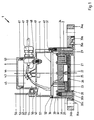
- a level measuring device 1 which has a housing 2, a hood 4 and a cover 6.
- a transmission and reception converter 21 is accommodated in the interior of the housing 2. It generates a transmission pulse directed at the surface of the medium to be measured and receives the echo reflected from the surface of the medium.
- the transmitting and receiving transducer 21 consists in a known manner of a piezoceramic element 22, an adaptation layer 23, a damping layer 24 and a membrane 25.
- the layers 23, 24 consist of a silicone elastomer.
- the piezoceramic element 22 is connected to the membrane 25 via spacers 26. To protect the membrane 25, it is set back in a known manner in relation to the end of the housing 2 facing the filling material.
- the transducer 21 is not connected directly to the wall of the housing 2, but rather is arranged within a cylindrical depression 27 which extends axially from the diaphragm 25 and forms a Position coaxial to the axis of symmetry of the housing 2.
- the trough 27 and the housing 2 are connected to one another only via a short cylindrical section 28 and an annular cylindrical zone 29.
- cylindrical supports 31 are arranged in the interior of the housing 2 in the interior of the housing 2 .
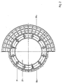
- the cylindrical supports 31 are integrally formed on the ring zone 29 and extend at the same distance from one another, arranged on a bolt circle, along the inner lateral surface of the housing 2. They assume such a position that they are not spatially connected to the outer surface of the housing 2 stand (Fig. 2). At her facing away from the ring zone 29 At the end, the cylindrical supports 31 are penetrated by an internal thread.
- the interior of the housing 2 is almost completely filled by the damping layer 24.
- the top of the damping layer 24 assumes a position that coincides approximately with the end of the supports 31. If the level measuring device 1 is to be inserted into a container whose internal pressure is above that of the normal atmosphere, the membrane 25 is also exposed to this pressure.
- the transmitting and receiving transducer 21 is closed off by a steel plate 32.
- the steel plate 32 lies on the damping layer 24 and is fastened to the cylindrical supports 31 by means of screw connections 33. The steel plate 32 then absorbs the internal pressure of the container via the membrane 25 and also prevents vibrational energy of the piezoceramic element 22 from being radiated through the damping layer 24, towards the side facing away from the membrane 25.
- the trough 27 extends spatially in such a way that, depending on the application, various types of piezoceramic elements, surrounded by an adaptation and damping layer, find space.
- the housing 2 is in a known manner as a molded part made of a thermoplastic and chemically resistant plastic, for. B. made of polyvinylidene fluoride. In order to be able to use such a plastic part in an explosive atmosphere, measures must be taken to prevent static charging.
- a sealing strip 30a or 30b is arranged on the housing 2 on the side facing the filling material. The sealing strip 30a or 30b has the task of closing the opening of a wall enclosing the filling material, through which the level measuring device 1 communicates with the filling material, including an annular flat seal, when the level measuring device 1 is attached to the wall.
- the design of the sealing strip 30a which extends to the right of the outer surface of the housing 2, is different from that of the sealing strip 30b, which extends to the left of the housing 2.
- the housing shapes are produced by an insert which is introduced into the injection mold in a known manner.
- the sealing strip 30a extends radially outward from the lateral surface of the housing 2.
- the sealing strip 30a is designed so that it can be encompassed by the shoulder 35a of a coupling flange 34a. It is designed in such a way that it can be encompassed by any flanges that are manufactured according to domestic and foreign flange standards.
- the sealing strip 30a is intended for large nominal widths and is formed from two separate annular sealing surfaces which extend outside the outer surface of the housing 2 and are simultaneously encompassed by the shoulder 35a of the flange 34a.
- the sealing strip 30b is in the Arranged inside the outer surface of the housing 2 and formed by a closed, annular sealing surface.
- one version of the housing 2 with the sealing strip 30b is sufficient.
- the sealing strips 30a, 30b are interrupted by partitions and cutouts, so that only small, continuous surfaces preventing a charge are present.
- Fig. 2 it is shown how these molded parts are designed by inserting ribs and breakouts.
- the hood 4 is also made as a molded part from a thermoplastic, advantageously from a polybutylene terephthalate.
- a circuit board 41 is arranged in its interior. On the circuit board (not shown) the electronic components are arranged, which form the electronic circuit of the level measuring device 1. The electronic parts are electrically connected to one another by conductor tracks (not shown). Furthermore, the printed circuit board 41 is connected by a connecting line 42 to terminals 43 which, arranged on a base 44, project into the connection space 45.
- the base 44 is designed in such a way that the terminal strip of the connecting terminal 43 is at an acute angle to the axis of symmetry of the hood 4, as a result of which the connection of the electrical line in the connecting space 45 is made considerably easier.
- connection cable 46 is connected, which connects the level measuring device 1 with an evaluation device and via which the measured values determined by the level measuring device 1 are transmitted to the evaluation device and also the energy necessary for the function of the level measuring device 1 is transmitted from the evaluation device.
- a PG screw connection 47 the connection cable 46 is inserted into the connection space 45 and the implementation is completed.
- connection space 45 also has a ground connection terminal 48. This is designed as a screw connection penetrating the intermediate wall 49.
- the intermediate wall 49 also has a further opening 50, which serves to lead the electrical connecting line 42 from the printed circuit board 41 to the connecting terminals 43.
- a screw connection 51 penetrates a collar formed on the hood 4.
- the tight connection between the housing 2 and the hood 4 is achieved in that the housing 2 has an annular web 36 and on the hood 4 a collar 52 revolves around the outer surface, which on the housing 2 facing side is pierced by a groove which surrounds the web 36.
- connection space 45 is closed on the side facing away from the membrane 25 by means of the cover 6.
- the cover 6 is supported on a collar 61 which lies opposite the annular end face 53 of the hood 4.
- a circumferential groove in which an annular seal 63 is arranged, is formed on the cylindrical region 62 and breaks through the lateral surface.
- the ring-shaped seal 63 can be formed from a commercially available O-ring.
- the hood 4 is designed so that the fill level measuring device 1 can in turn be designed in two different embodiments. For use in a normal atmosphere, the hood 4 is designed as it has just been shown. For use in an explosive medium, however, it is necessary to hermetically seal the live parts of the circuit board 41 from the outside world.
- a commercially available casting compound 57 is filled with the cover 6 open through the recess 50 into the interior of the hood 4 until the interior is completely filled up to the partition 49 and the electrical components including the printed circuit board 41 are surrounded by the casting compound.
- a bushes 54 are formed above the partition 49, which are diametrically opposite. For the sake of better illustration, only one of the two bushes 54 is shown in FIG. 1.
- the bushes 54 are penetrated by a thread and, together with a screw 55, form a screw connection through which a bracket 56 is fastened to the hood 4. With the aid of the bracket 56, it is possible to suspend the level sensor 1 deflected in all directions on the container wall or the ceiling of a container or over an open channel, the flange connection 34a or 34b naturally being omitted.
Landscapes
- Physics & Mathematics (AREA)
- Engineering & Computer Science (AREA)
- Acoustics & Sound (AREA)
- General Physics & Mathematics (AREA)
- Multimedia (AREA)
- Computer Networks & Wireless Communication (AREA)
- Radar, Positioning & Navigation (AREA)
- Remote Sensing (AREA)
- Electromagnetism (AREA)
- Thermal Sciences (AREA)
- Fluid Mechanics (AREA)
- Measurement Of Levels Of Liquids Or Fluent Solid Materials (AREA)
Abstract
Description
- Die Erfindung betrifft ein Füllstandsmeßgerät zum Messen des Füllstands in einem Behälter mit einem Schall- oder Ultraschallwandler, welcher einen Sendeimpuls auf das Füllgut in dem Behälter richtet und das am Füllgut reflektierte Echosignal empfängt, und mit einer elektronischen Schaltung, welche den Schall- oder Ultraschallwandler zu Schwingungen erregt und das empfangene Echosignal in ein elektrisches Signal umwandelt und zu einem Auswertegerät überträgt sowie die für die Funktion des Füllstandsmeßgeräts notwendige Energie von dem Auswertegerät empfängt, wobei der Schall- oder Ultraschallwandler eine von einem Gehäuse umschlossene erste Funktionseinheit und die elektronische Schaltung eine von einem Gehäuse umschlossene zweite Funktionseinheit bilden.
- Bei einem aus dem Dokument DE-U1-86 30 763.0 bekannten Füllstandsmeßgerät dieser Art, das insbesondere zur Verwendung bei aggressiven Medien bestimmt ist, ist das den Schall- oder Ultraschallwandler umschließende Gehäuse ein topfförmiges Kunststoffteil, das mittels eines angeformten Ringansatzes an der dem Behälter zugewandten Fläche eines Flansches befestigt ist, so daß es den Schall- oder Ultraschallwandler behälterseitig umschließt. Das die elektronische Schaltung umschließende Gehäuse ist auf der dem Behälter abgewandten Seite des Flansches befestigt, und die elektronische Schaltung ist mit dem Schall- oder Ultraschallwandler durch eine Leitung verbunden, die durch den Flansch hindurchgeführt ist. Zur Befestigung des Füllstandsmeßgeräts am Behälter wird der Flansch mit einem Gegenflansch verbunden, der eine kreiszylindrische Behälteröffnung umgibt, durch die dann das Wandlergehäuse in den Innenraum des Behälters ragt. Bei diesem Füllstandsmeßgerät ist zwar das Wandlergehäuse ein einfaches und billiges Kunststoffteil, doch erfüllt das Füllstandsmeßgerät wegen der exponierten Lage des verletzlichen Wandlergehäuses nicht die Anforderungen, die für den Einsatz in explosionsgefährdeten Bereichen gestellt werden. Ferner ist der Flansch, der auf der einen Seite das Wandlergehäuse mit dem Schall- oder Ultraschallwandler und auf der anderen Seite das Gehäuse mit der elektronischen Schaltung trägt, ein integrierter Bestandteil des Füllstandsmeßgeräts.
- In ähnlicher Weise ist ein aus dem Dokument GB-A-2 195 445 bekanntes Füllstandsmeßgerät gebildet und montiert, jedoch mit dem Unterschied, daß der Schall- oder Ultraschallwandler in einer im Flansch gebildeten kreiszylindrischen Ausnehmung angeordnet ist, deren Boden die Membran des Schall- oder Ultraschallwandlers bildet. Somit ist die Membran einstückig mit dem Flansch ausgebildet, so daß dem Innenraum des Behälters eine homogene durchgehende Fläche zugewandt ist. Auch in diesem Fall bildet der Flansch einen integrierten Bestandteil des Füllstandsmeßgeräts, dessen Herstellung wegen der erforderlichen Präzisionsverarbeitung des metallischen Flansches sehr aufwendig ist. Zwar könnte das gleiche Füllstandsmeßgerät auch in nicht explosionsgefährdeten Bereichen verwendet werden, doch wären dort die erheblichen Herstellungskosten nicht gerechtfertigt.
- Diese bekannten Füllstandsmeßgeräte sind somit jeweils für einen bestimmten Verwendungszweck ausgebildet; sie lassen sich nicht ohne weiteres an einen anderen Verwendungszweck anpassen.
- Aufgabe der Erfindung ist die Schaffung eines Füllstandsmeßgeräts der eingangs angegebenen Art, das kostengünstig herstellbar ist und für unterschiedliche Anwendungen, insbesondere auch bei aggressiven Medien oder in explosionsgefährdeten Bereichen, geeignet ist.
- Zur Lösung dieser Aufgabe ist das Füllstandsmeßgerät nach der Erfindung durch die folgenden Merkmale gekennzeichnet:
- a) das die elektronische Schaltung umschließende Gehäuse ist eine Haube, die lösbar mit dem Gehäuse des Schall- oder Ultraschallwandlers verbunden ist;
- b) das Gehäuse des Schall- oder Ultraschallwandlers ist mittels eines Überwurfflansches, der einen sich von der Mantelfläche des Gehäuses radial nach außen erstreckenden Bund umschließt, an einer Wand des Behälters befestigt;
- c) der Schall- oder Ultraschallwandler ist schallentkoppelt in einer im Gehäuse geformten Mulde angeordnet;
- d) der Schall- oder Ultraschallwandler ist auf seiner dem Füllgut abgewandten Seite von einer Stahlplatte abgedeckt, welche sich an den Innenraum des Gehäuses durchdringenden, an einer Ringzone des Gehäuses angeformten Stützen abstützt;
- e) an der Haube ist ein Anschlußraum angeformt, in dem elektrische Anschlußelemente angeordnet sind und der durch einen Deckel verschließbar ist.
- Im Gegensatz zu den Füllstandsmeßgeräten des Standes der Technik, bei denen der Befestigungsflansch ein wesentlicher integrierter Bestandteil des Geräts ist, besteht das erfindungsgemäße Füllstandsmeßgerät aus zwei Funktionseinheiten, deren Gehäuse unabhängig von einem Befestigungsflansch ausgebildet und direkt miteinander lösbar verbunden sind. Das Füllstandsmeßgerät kann daher ohne den Befestigungsflansch vollständig zusammengebaut werden und wahlweise auch auf andere Weise als durch Flanschbefestigung am Behälter angebracht werden. Die Gehäuse können auf einfache und kostengünstige Weise hergestellt werden, vorzugsweise als Kunststoff-Spritzteile. Bei geeigneter Wahl des Kunststoffs ist das Füllstandsmeßgerät zur Verwendung bei aggressiven Medien geeignet. Der Schall- oder Ultraschallwandler liegt geschützt in der im Gehäuse geformten Mulde, die zugleich eine gute Körperschallentkopplung zwischen dem Schall- oder Ultraschallwandler und dem mit dem Befestigungsflansch und der Behälterwand in Berührung stehenden äußeren Teil des Wandlergehäuses ergibt. Die Stahlplatte, die auf der dem Füllgut abgewandten Seite des Schall- oder Ultraschallwandlers angebracht ist, verhindert eine übermäßige Deformation der Wandlermembran bei einem plötzlichen Druckanstieg im Behälter. Dadurch ist das Füllstandsmeßgerät auch für einen Einsatz in explosionsgefährdeten Bereichen geeignet.
- Vorteilhafte Ausgestaltungen undd Weiterbildungen der Erfindung sind in den Unteransprüchen gekennzeichnet.
- Ein Ausführungsbeispiel der Erfindung wird anhand der Zeichnung beschrieben. In der Zeichnung zeigen:
- Fig. 1
- einen Schnitt durch ein Füllstandsmeßgerät nach der Erfindung und
- Fig. 2
- eine Draufsicht auf das Wandlergehäuse des Füllstandsmeßgeräts von Fig. 1.
- In Fig. 1 ist ein Füllstandsmeßgerät 1 dargestellt, das ein Gehäuse 2, eine Haube 4 und einen Deckel 6 aufweist.
- In Inneren des Gehäuses 2 ist ein Sende- und Empfangswandler 21 untergebracht. Er erzeugt einen auf die Oberfläche des zu messenden Füllgutes gerichteten Sendeimpuls und empfängt das von der Oberfläche des Füllgutes reflektierte Echo. Der Sende- und Empfangswandler 21 besteht in bekannter Weise aus einem piezokeramischen Element 22, einer Anpaßschicht 23, einer Dämpfungsschicht 24 und einer Membran 25. Die Schichten 23, 24 bestehen aus einem Silikonelastomer. Das piezokeramische Element 22 steht über Distanzstücke 26 mit der Membran 25 in Verbindung. Zum Schutz der Membran 25 ist diese in bekannter Weise gegenüber dem dem Füllgut zugewandten ende des Gehäuses 2 ein Stück zurückversetzt.
- Um eine Körperschallentkopplung zwischen dem Sende- und Empfangswandler 21 und dem Gehäuse 2 zu erzielen, ist der Wandler 21 nicht unmittelbar mit der Wand des Gehäuses 2 verbunden, sondern innerhalb einer zylindrischen Mulde 27 angeordnet, welche sich axialer Richtung von der Membran 25 erstreckt und eine Lage koaxial zur Symmetrieachse des Gehäuses 2 einnimmt. Die Mulde 27 und das Gehäuse 2 sind lediglich über einen kurzen zylindrischen Abschnitt 28 und eine ringzylindrische Zone 29 miteinander verbunden.
- In Inneren des Gehäuses 2 sind weiter zylindrische Stützen 31 angeordnet. Die zylindrischen Stützen 31 sind an der Ringzone 29 angeformt und erstrecken sich in gleichem Abstand voneinander, auf einem Lochkreis angeordnet, entlang der inneren Mantelfläche des Gehäuses 2. Dabei nehmen sie eine solche Lage ein, daß sie in keiner räumlichen Verbindung zu der Mantelfläche des Gehäuses 2 stehen (Fig. 2). An ihrem der Ringzone 29 abgewandten Ende sind die zylindrische Stützen 31 von einem Innengewinde durchdrungen.
- Das Innere des Gehäuses 2 ist fast vollkommen von der Dämpfungsschicht 24 ausgefüllt. Die Oberseite der Dämpfungsschicht 24 nimmt eine Lage ein, die etwa mit dem Ende der Stützen 31 zusammenfällt. Soll das Füllstandsmeßgerät 1 in einen Behälter eingesetzt werden, dessen innerer Druck über dem der normalen Atmosphäre liegt, wird auch die Membran 25 diesem Druck ausgesetzt. Um ein Durchbiegen der Membran 25 zu verhindern, ist der Sende- und Empfangswandler 21 durch eine Stahlplatte 32 abgeschlossen. Die Stahlplatte 32 liegt auf der Dämpfungsschicht 24 auf und ist mittels Schraubverbindungen 33 an den zylindrischen Stützen 31 befestigt. Die Stahlplatte 32 nimmt dann den Innendruck des Behälters über die Membran 25 auf und verhindert außerdem, daß Schwingungsenergie des piezokeramischen Elementes 22 durch die Dämpfungsschicht 24, nach der der Membran 25 abgewandten Seite abgestrahlt wird.
- Die Mulde 27 erstreckt sich räumlich derart, daß in ihr, je nach Anwendungszweck, verschiedenartige piezokeramische Elemente, von einer Anpaß- und Dämpfungsschicht umgeben, Platz finden.
- Das Gehäuse 2 ist in bekannter Weise als Spritzteil aus einem thermoplastischen und chemisch beständigen Kunststoff, z. B. aus Polyvinylidenfluorid hergestellt. Um ein solches Kunststoffteil in einer explosiblen Atmosphäre einsetzen zu könne, müssen Maßnahmen getroffen sein, um ein statische Aufladung zu verhindern. An dem Gehäuse 2 ist an der dem Füllgut zugewandten Seite eine Dichtleiste 30a bzw. 30b angeordnet. Die Dichtleiste 30a bzw. 30b hat zur Aufgabe, die Öffnung einer das Füllgut umschließenden Wandung, durch welche das Füllstandsmeßgerät 1 mit dem Füllgut in Verbindung tritt, unter Einschluß einer ringförmigen flachen Dichtung abzuschließen, wenn das Füllstandmeßgerät 1 an der Wandung befestigt wird.
- Die Gestaltung der Dichtleiste 30a, welche sich rechts von der Mantelfläche des Gehäuses 2 erstreckt, ist eine andere wie die jenige der Dichtleiste 30b, welche sich auf der linken Seite des Gehäuses 2 erstreckt. Damit soll dargestellt werden, daß das Gehäuse 2 in zwei verschiedenen Varianten entsprechend dem Anwendungsfall ausgeführt werden kann. Die Gehäuseformen werden dabei durch ein in bekannter Weise, in die Spritzform eingebrachtes Einlegeteil hergestellt. Die Dichtleiste 30a erstreckt sich radial von der Mantelfläche des Gehäuses 2 nach außen. Wie aus Fig. 1 ersichtlich, ist die Dichtleiste 30a so gestaltet, daß sie von der Schulter 35a eines Überwurfflansches 34a umfaßt werden kann. Sie ist dabei so gestaltet, daß sie von beliebigen, d. h., nach in- und ausländischen Flanschnormen hergestellten Flanschen umfaßt werden kann. Die Dichtleiste 30a ist für große Nennweiten gedacht und aus zwei getrennten ringförmigen Dichtflächen gebildet, welche sich außerhalb der Mantelfläche des Gehäuses 2 erstrecken und gleichzeitig von der Schulter 35a des Flansches 34a umfaßt werden. Die Dichtleiste 30b ist im Inneren der Mantelfläche des Gehäuses 2 angeordnet und durch eine geschlossene, ringförmige Dichtfläche gebildet. Ein Bund 30c des Gehäuses 2, welcher einer Schulter 35b eines Überwurfflansches 34b gegenüberliegt und von ihr umfaßt wird, erstreckt sich radial anschließend an die Dichtleiste 30b von der Mantelfläche des Gehäuses 2 nach außen.
- Für die kleineren Nennweiten genügt eine Ausführung des Gehäuses 2 mit der dichtleiste 30b.
- Zur Verhinderung der durch Reibung verursachten statischen Aufladung sind die Dichtleisten 30a, 30b durch Zwischenwände und Aussparungen unterbrochen, so, daß nur kleine, eine Aufladung verhindernde, durchgehende Flächen vorhanden sind. In Fig. 2 ist aufgezeigt, wie diese angeformten Teile durch Einfügung von Rippen und Ausbrüchen gestaltet sind.
- Die Haube 4 ist ebenfalls als Spritzteil aus einem thermoplastischen Kunststoff, vorteilhaft aus einem Polybutylenterephtalat hergestellt. In ihrem Inneren ist eine Leiterplatte 41 angeordnet. Auf der Leiterplatte sind (nicht dargestellt) die elektronischen Bauelemente angeordnet, welche die elektronische Schaltung des Füllstandsmeßgerätes 1 bilden. Die elektronischen Teile sind durch (nicht dargestellte) Leiterbahnen elektrisch miteinander verbunden. Weiter ist die Leiterplatte 41 durch eine Verbindungsleitung 42 mit Anschlußklemmen 43 verbunden, welche auf einem Sockel 44 angeordnet in den Anschlußraum 45 ragen. Der Sockel 44 ist so gestaltet, daß die Klemmenleiste der Anschlußklemme 43 in einem spitzen Winkel zur Symmetrieachse der Haube 4 steht, wodurch das Anscließen der elektrischen Leitung in dem Anschlußraum 45 wesentlich erleichtert wird. An den Klemmen 43 ist das Ansclußkabel 46 angeschlossen, welche das Füllstandsmeßgerät 1 mit einem auswertegerät verbindet und über welches die von dem Füllstandsmeßgerät 1 ermittelten Meßwerte zum Auswertegerät übertragen werden und auch die für die Funktion des Füllstandsmeßgerätes 1 notwendige Energie von dem Auswertegerät übertragen wird. Mittels einer PG-Verschraubung 47 wird das Anschlußkabel 46 in den Anschlußraum 45 eingeführt und die Durchführung abgeschlossen.
- Der Anschlußraum 45 weist noch eine Masseanschlußklemme 48 auf. Diese ist als eine die Zwischenwand 49 durchdringende Schraubverbindung gestaltet. Die Zwischenwand 49 weist noch einen weiteren Durchbruch 50 auf, welcher der Durchführung der elektrischen Verbindungsleitung 42 von der Leiterplatte 41 zu den Anschlußklemmen 43 dient. Zur Verbindung mit dem Gehäuse 2 durchdringt eine Schraubverbindung 51 einen an der Haube 4 angeformten Bund. Die dichte Verbindung zwischen dem Gehäuse 2 und der Haube 4 wird dadurch erreicht, daß das Gehäuse 2 einen ringförmigen Steg 36 aufweist und an der Haube 4 ein Bund 52 die Mantelfläche umläuft, der auf seiner dem Gehäuse 2 zugewandten Seite von einer Nut durchbrochen ist, welche den Steg 36 umschließt.
- Der Anschlußraum 45 ist auf der der Membran 25 abgewandten Seite mittels des Deckels 6 verschlossen. Dabei stützt sich der Deckel 6 an einem Bund 61 ab, welcher der ringförmigen Stirnfläche 53 der Haube 4 gegenüberliegt. Zur Abdichtung des Deckels 6 in der Haube 4 ist an dem zylindrischen Bereich 62 eine die Mantelfläche durchbrechende, umlaufende Nut angeformt, in welcher eine ringförmige Dichtung 63 angeordnet ist. Die ringförmige Dichtung 63 kann aus einem handelsüblichen O-Ring gebildet sein. Die Haube 4 ist so gestaltet, daß das Füllstandsmeßgerät 1 wiederum in zwei verschiedenen Ausführungsformen gestaltet werden kann. Für den Einsatz in normaler Atmosphäre ist die Haube 4 so gestaltet, wie es soeben dargestellt wurde. Für den Einsatz in einem explosiblen Medium, ist es jedoch erforderlich, die stromführenden Teile der Leiterplatte 41 hermetisch von der Außenwelt abzuschließen. Dazu wird eine handelsübliche Vergußmasse 57 bei geöffnetem Deckel 6 durch die Aussparung 50 in den Innenraum der Haube 4 gefüllt, bis der Innenraum bis zur Trennwand 49 gänzlich gefüllt und die auf der Leiterplatte 41 angeordneten elektrischen Bauelemente einschließlich der Leiterplatte von der Vergußmasse umgeben sind.
- An der Außenwand der Haube 4 sind oberhalb der Trennwand 49 zwei Buchsen 54 angeformt, welche sich diametral gegenüberliegen. Der besseren Darstellung wegen, ist in Fig. 1 nur eine der beiden Buchsen 54 gezeigt. Die Buchsen 54 sind von einem Gewinde durchdrungen und bilden zusammen mit einer Schraube 55 eine Schraubverbindung, durch welche ein Bügel 56 an der Haube 4 befestigt ist. Mit Hilfe des Bügels 56 ist es möglich, den Füllstandssensor 1 an der Behälterwand oder der Decke eines Behälters oder über einem offenen Gerinne in alle Richtungen ausgelenkt aufzuhängen, wobei selbstverständlich die Flanschverbindung 34a bzw. 34b entfällt.
Claims (8)
- Füllstandsmeßgerät zum Messen des Füllstands in einem Behälter mit einem Schall- oder Ultraschallwandler (21), welcher einen Sendeimpuls auf das Füllgut in dem Behälter richtet und das am Füllgut reflektierte Echosignal empfängt, und mit einer elektronischen Schaltung (41), welche den Schall- oder Ultraschallwandler (21) zu Schwingungen erregt und das empfangene Echosignal in ein elektrisches Signal umwandelt und zu einem Auswertegerät überträgt sowie die für die Funktion des Füllstandsmeßgeräts notwendige Energie von dem Auswertegerät empfängt, wobei der Schall- oder Ultraschallwandler (21) eine von einem Gehäuse (2) umschlossene erste Funktionseinheit und die elektronische Schaltung eine von einem Gehäuse umschlossene zweite Funktionseinheit bilden,
gekennzeichnet durch die folgenden Merkmale:a) das die elektronische Schaltung (41) umschließende Gehäuse ist eine Haube (4), die lösbar mit dem Gehäuse (2) des Schall- oder Ultraschallwandlers (21) verbunden ist;b) das Gehäuse (2) des Schall- oder Ultraschallwandlers (21) ist mittels eines Überwurfflansches (34a, 34b), der einen sich von der Mantelfläche des Gehäuses (2) radial nach außen erstreckenden Bund (30a, 30c) umschließt, an einer Wand des Behälters befestigt;c) der Schall- oder Ultraschallwandler (21) ist schallentkoppelt in einer im Gehäuse (2) geformten Mulde (27) angeordnet;d) der Schall- oder Ultraschallwandler (21) ist auf seiner dem Füllgut abgewandten Seite von einer Stahlplatte (32) abgedeckt, welche sich an den Innenraum des Gehäuses (2) durchdringenden, an einer Ringzone (29) des Gehäuses (2) angeformten Stützen (31) abstützt;e) an der Haube (4) ist ein Anschlußraum (45) angeformt, in dem elektrische Anschlußelemente (43) angeordnet sind und der durch einen Deckel (6) verschließbar ist. - Füllstandsmeßgerät nach Anspruch 1, dadurch gekennzeichnet, daß der sich radial von der Mantelfläche des Gehäuses (2) nach außen erstreckende Bund als Dichtleiste (30a) ausgebildet ist, welche zwei getrennte, ringförmige Dichtflächen aufweist und von einer Schulter (35a) des Überwurfflansches (34a) umfaßt wird.
- Füllstandsmeßgerät nach Anspruch 1, dadurch gekennzeichnet, daß das Gehäuse (2) eine innerhalb seiner Mantelfläche umlaufende ringförmige Dichtleiste (30b) aufweist, welche eine geschlossene ringförmige Dichtfläche bildet und an die sich der Bund (30c) anschließt, der sich radial von der Mantelfläche des Gehäuses (2) nach außen erstreckt und von einer Schulter (35b) des Überwurfflansches (34b) umfaßt wird.
- Füllstandsmeßgerät nach Anspruch 2 oder 3, dadurch gekennzeichnet, daß die ringförmige Dichtleiste (30a bzw. 30b) durch Zwischenwände und Aussparungen unterbrochen ist.
- Füllstandsmeßgerät nach einem der Ansprüche 1 bis 4, dadurch gekennzeichnet, daß die Stahlplatte (32) durch Schraubverbindungen (33) mit den Stützen (31) verbunden ist.
- Füllstandsmeßgerät nach einem der Ansprüche 1 bis 5, dadurch gekennzeichnet, daß das Gehäuse (2) und die Haube (4) als Spritzteile aus einem thermoplastischen Kunststoff gebildet sind.
- Füllstandsmeßgerät nach einem der Ansprüche 1 bis 6, dadurch gekennzeichnet, daß die im Inneren der Haube (4) angeordnete elektronische Schaltung auf einer Leiterplatte (41) gebildet ist.
- Füllstandsmeßgerät Anspruch 7, dadurch gekennzeichnet, daß der Schall- oder Ultraschallwandler (21) mittels einer trennbaren elektrischen Leitung (42) mit der Leiterplatte (41) und die Leiterplatte (41) weiter über die elektrischen Anschlußelemente (43) und ein Verbindungskabel (46) mit dem Auswertegerät in elektrischer Verbindung stehen.
Applications Claiming Priority (3)
| Application Number | Priority Date | Filing Date | Title |
|---|---|---|---|
| DE3933474A DE3933474C2 (de) | 1989-10-06 | 1989-10-06 | Füllstandsmeßgerät |
| DE3933474 | 1989-10-06 | ||
| PCT/DE1990/000761 WO1991005226A1 (de) | 1989-10-06 | 1990-10-05 | Aus bauelementen zusammensetzbares füllstandsmessgerät |
Publications (2)
| Publication Number | Publication Date |
|---|---|
| EP0447516A1 EP0447516A1 (de) | 1991-09-25 |
| EP0447516B1 true EP0447516B1 (de) | 1995-08-23 |
Family
ID=6390998
Family Applications (1)
| Application Number | Title | Priority Date | Filing Date |
|---|---|---|---|
| EP90914507A Expired - Lifetime EP0447516B1 (de) | 1989-10-06 | 1990-10-05 | Aus bauelementen zusammensetzbares füllstandsmessgerät |
Country Status (8)
| Country | Link |
|---|---|
| US (1) | US5363341A (de) |
| EP (1) | EP0447516B1 (de) |
| JP (1) | JPH0676906B2 (de) |
| AU (1) | AU633632B2 (de) |
| CA (1) | CA2042383C (de) |
| DE (2) | DE3933474C2 (de) |
| HU (1) | HU207159B (de) |
| WO (1) | WO1991005226A1 (de) |
Cited By (1)
| Publication number | Priority date | Publication date | Assignee | Title |
|---|---|---|---|---|
| EP4418008A3 (de) * | 2023-02-20 | 2024-12-18 | Autonics Corporation | Sensorvorrichtung |
Families Citing this family (30)
| Publication number | Priority date | Publication date | Assignee | Title |
|---|---|---|---|---|
| DE4311963C2 (de) * | 1993-04-10 | 1996-10-24 | Endress Hauser Gmbh Co | Füllstandsmeßgerät |
| US5550790A (en) * | 1995-02-10 | 1996-08-27 | Kistler-Morse Corporation | Acoustic transducer for level measurement in corrosive chemical environments |
| DE59510158D1 (de) * | 1995-09-28 | 2002-05-16 | Endress Hauser Gmbh Co | Ultraschallwandler |
| DE19538677C2 (de) * | 1995-10-17 | 1998-12-17 | Endress Hauser Gmbh Co | Anordnung zur Überwachung eines vorbestimmten Füllstands einer Flüssigkeit in einem Behälter |
| DE19538696C2 (de) * | 1995-10-17 | 1997-09-25 | Endress Hauser Gmbh Co | Anordnung zur Überwachung eines vorbestimmten Füllstands einer Flüssigkeit in einem Behälter |
| DE19538680C2 (de) * | 1995-10-17 | 1998-10-08 | Endress Hauser Gmbh Co | Anordnung zur Überwachung eines vorbestimmten Füllstands einer Flüssigkeit in einem Behälter |
| US5962952A (en) * | 1995-11-03 | 1999-10-05 | Coherent Technologies, Inc. | Ultrasonic transducer |
| US5598845A (en) * | 1995-11-16 | 1997-02-04 | Stellartech Research Corporation | Ultrasound transducer device for continuous imaging of the heart and other body parts |
| US5822274A (en) * | 1996-04-12 | 1998-10-13 | Flowline Inc. | Method and apparatus for acoustically measuring the level of liquid in a tank |
| US5944317A (en) * | 1997-07-07 | 1999-08-31 | Rohrbaugh; George Wilson | Shock wave scoring apparatus employing dual concentric curved rod sensors |
| DE19755729A1 (de) * | 1997-12-15 | 1999-06-17 | Bosch Gmbh Robert | Ultraschallsensor |
| DK0945714T3 (da) | 1998-03-17 | 2011-01-31 | Endress & Hauser Deutschland Ag & Co Kg | Elektronisk udstyr til brug i eksplosionsudsatte områder |
| GB9910130D0 (en) * | 1999-04-30 | 1999-06-30 | Motosonics Ltd | Sensor apparatus |
| DK200101780A (da) * | 2001-11-30 | 2002-11-27 | Danfoss As | Ultralydstransducer |
| DE10250065A1 (de) * | 2002-10-25 | 2004-05-06 | Endress + Hauser Flowtec Ag, Reinach | Prozeß-Meßgerät |
| US7098669B2 (en) | 2003-10-01 | 2006-08-29 | Flowline, Inc. | Depth determining system |
| US7363811B2 (en) * | 2005-04-07 | 2008-04-29 | Endress + Hauser Flowtec Ag | Measurement pickup |
| DE102007021099A1 (de) | 2007-05-03 | 2008-11-13 | Endress + Hauser (Deutschland) Ag + Co. Kg | Verfahren zum Inbetriebnehmen und/oder Rekonfigurieren eines programmierbaren Feldmeßgeräts |
| DE102007058608A1 (de) | 2007-12-04 | 2009-06-10 | Endress + Hauser Flowtec Ag | Elektrisches Gerät |
| DE102008022373A1 (de) | 2008-05-06 | 2009-11-12 | Endress + Hauser Flowtec Ag | Meßgerät sowie Verfahren zum Überwachen eines Meßgeräts |
| JP5075171B2 (ja) * | 2009-09-02 | 2012-11-14 | パナソニック株式会社 | 超音波センサ |
| WO2011131399A1 (de) | 2010-04-19 | 2011-10-27 | Endress+Hauser Flowtec Ag | Treiberschaltung für einen messwandler sowie damit gebildetes messsystem |
| DE202010006553U1 (de) | 2010-05-06 | 2011-10-05 | Endress + Hauser Flowtec Ag | Elektronisches Meßgerät mit einem Optokoppler |
| DE102010030924A1 (de) | 2010-06-21 | 2011-12-22 | Endress + Hauser Flowtec Ag | Elektronik-Gehäuse für ein elektronisches Gerät bzw. damit gebildetes Gerät |
| DE102011076838A1 (de) | 2011-05-31 | 2012-12-06 | Endress + Hauser Flowtec Ag | Meßgerät-Elektronik für ein Meßgerät-Gerät sowie damit gebildetes Meßgerät-Gerät |
| US11566932B2 (en) * | 2014-07-09 | 2023-01-31 | Husky Corporation | Sonic monitor system for a tank |
| DE102016114860A1 (de) | 2016-08-10 | 2018-02-15 | Endress + Hauser Flowtec Ag | Treiberschaltung sowie damit gebildete Umformer-Elektronik bzw. damit gebildetes Meßsystem |
| US11274867B2 (en) * | 2020-03-26 | 2022-03-15 | Joshua R&D Technologies, LLC | Dynamic fine tuning of the refrigerant pressure and charge in a refrigeration system |
| EP4083583A1 (de) * | 2021-04-30 | 2022-11-02 | Tekelek Group Holdings Limited | Ultraschallabstandssensor und verfahren zum schutz eines ultraschallwandlers in einem ultraschallabstandssensor |
| DE102021132304A1 (de) * | 2021-12-08 | 2023-06-15 | Endress+Hauser SE+Co. KG | Feldgerät der Prozess- und Automatisierungstechnik |
Family Cites Families (9)
| Publication number | Priority date | Publication date | Assignee | Title |
|---|---|---|---|---|
| JPS563429B2 (de) * | 1973-11-01 | 1981-01-24 | ||
| US3910116A (en) * | 1973-12-07 | 1975-10-07 | Rexnord Inc | Transducer positioning means for fluid level monitoring |
| US4183007A (en) * | 1978-02-22 | 1980-01-08 | Fischer & Porter Company | Ultrasonic transceiver |
| DK147718C (da) * | 1982-07-21 | 1985-05-13 | Nils Jensen | Ultralydapparat til niveaumaaling i tanke eller lignende forraadsrum |
| DE8332045U1 (de) * | 1983-11-08 | 1984-02-23 | Endress U. Hauser Gmbh U. Co, 7867 Maulburg | Ultraschallsensor eines Füllstandsmeßgerätes |
| DE3416254C2 (de) * | 1984-05-02 | 1986-06-19 | VEGA Grieshaber GmbH & Co, 7620 Wolfach | Vorrichtung zur Feststellung eines bestimmten Füllstandes eines Füllgutes in einem Behälter |
| DE3633047A1 (de) * | 1986-09-29 | 1988-04-07 | Endress Hauser Gmbh Co | Fuellstandmessgeraet zur messung des fuellstandes von explosiblen oder aggresiven medien in einem behaelter |
| DE8630763U1 (de) * | 1986-11-17 | 1987-03-12 | Endress U. Hauser Gmbh U. Co, 7867 Maulburg | Schall- oder Ultraschallsensor |
| GB8709903D0 (en) * | 1987-04-27 | 1987-06-03 | Gec Avionics | Sensor apparatus |
-
1989
- 1989-10-06 DE DE3933474A patent/DE3933474C2/de not_active Expired - Fee Related
-
1990
- 1990-10-05 EP EP90914507A patent/EP0447516B1/de not_active Expired - Lifetime
- 1990-10-05 JP JP2513532A patent/JPH0676906B2/ja not_active Expired - Fee Related
- 1990-10-05 AU AU64406/90A patent/AU633632B2/en not_active Ceased
- 1990-10-05 US US07/689,830 patent/US5363341A/en not_active Expired - Fee Related
- 1990-10-05 WO PCT/DE1990/000761 patent/WO1991005226A1/de not_active Ceased
- 1990-10-05 DE DE59009559T patent/DE59009559D1/de not_active Expired - Fee Related
- 1990-10-05 HU HU907908A patent/HU207159B/hu unknown
- 1990-10-05 CA CA002042383A patent/CA2042383C/en not_active Expired - Fee Related
Cited By (1)
| Publication number | Priority date | Publication date | Assignee | Title |
|---|---|---|---|---|
| EP4418008A3 (de) * | 2023-02-20 | 2024-12-18 | Autonics Corporation | Sensorvorrichtung |
Also Published As
| Publication number | Publication date |
|---|---|
| EP0447516A1 (de) | 1991-09-25 |
| HU907908D0 (en) | 1991-08-28 |
| HUT57895A (en) | 1991-12-30 |
| JPH0676906B2 (ja) | 1994-09-28 |
| CA2042383A1 (en) | 1991-04-07 |
| CA2042383C (en) | 1996-03-19 |
| US5363341A (en) | 1994-11-08 |
| DE59009559D1 (de) | 1995-09-28 |
| WO1991005226A1 (de) | 1991-04-18 |
| AU6440690A (en) | 1991-04-28 |
| DE3933474C2 (de) | 1994-01-27 |
| DE3933474A1 (de) | 1991-04-25 |
| HU207159B (en) | 1993-03-01 |
| JPH03505133A (ja) | 1991-11-07 |
| AU633632B2 (en) | 1993-02-04 |
Similar Documents
| Publication | Publication Date | Title |
|---|---|---|
| EP0447516B1 (de) | Aus bauelementen zusammensetzbares füllstandsmessgerät | |
| EP0984248B1 (de) | Messaufnehmer | |
| DE3633047C2 (de) | ||
| EP0769684B1 (de) | Anordnung zur Überwachung eines vorbestimmten Füllstands einer Flüsssigkeit in einem Behälter | |
| DE3539555A1 (de) | Mikrowellen-fuellstandsmesssystem | |
| EP3055858B1 (de) | Ultraschallsensor | |
| DE19538677C2 (de) | Anordnung zur Überwachung eines vorbestimmten Füllstands einer Flüssigkeit in einem Behälter | |
| WO1997026646A1 (de) | Bedämpfter ultraschallwandler | |
| DE19649679B4 (de) | Schwingungserfassungssensor | |
| WO1999053475A1 (de) | Kontaktelement für einen ultraschallsensor | |
| WO2000079513A1 (de) | Dämpfende halterung für das gehäuse eines ultraschallwandlers und verfahren zur herstellung | |
| DE102011106158A1 (de) | Sensor mit Laser-geschweißtem Deckel | |
| EP3588017A1 (de) | Ultraschallmessvorrichtung | |
| EP1040365B1 (de) | Ultraschallsensor | |
| DE102016224083A1 (de) | Elektrische Baugruppe | |
| EP3168579A1 (de) | Hornantenne | |
| EP3444573A1 (de) | Schallkopf für einen durchflussmesser mit ausziehmitteln | |
| DE4328366C3 (de) | Näherungsschalter | |
| EP2131353A1 (de) | Ultraschallwandler | |
| EP4094056B1 (de) | Sensorvorrichtung zum erfassen eines füllstands und/oder einer qualität eines fluids, und verfahren zum herstellen derselben | |
| DE102014220974A1 (de) | Sensoranordnung und Verfahren zur Herstellung einer Sensoranordnung | |
| EP3868481B1 (de) | Ultraschallsensor | |
| EP3444574A1 (de) | Schallkopf für einen durchflussmesser mit gestufter seitenwand | |
| DE102018200315A1 (de) | Schallwandler | |
| DE4126399C2 (de) |
Legal Events
| Date | Code | Title | Description |
|---|---|---|---|
| PUAI | Public reference made under article 153(3) epc to a published international application that has entered the european phase |
Free format text: ORIGINAL CODE: 0009012 |
|
| 17P | Request for examination filed |
Effective date: 19910524 |
|
| AK | Designated contracting states |
Kind code of ref document: A1 Designated state(s): CH DE FR GB IT LI SE |
|
| 17Q | First examination report despatched |
Effective date: 19940105 |
|
| GRAA | (expected) grant |
Free format text: ORIGINAL CODE: 0009210 |
|
| ITF | It: translation for a ep patent filed | ||
| AK | Designated contracting states |
Kind code of ref document: B1 Designated state(s): CH DE FR GB IT LI SE |
|
| REF | Corresponds to: |
Ref document number: 59009559 Country of ref document: DE Date of ref document: 19950928 |
|
| ET | Fr: translation filed | ||
| GBT | Gb: translation of ep patent filed (gb section 77(6)(a)/1977) |
Effective date: 19951130 |
|
| PLBE | No opposition filed within time limit |
Free format text: ORIGINAL CODE: 0009261 |
|
| STAA | Information on the status of an ep patent application or granted ep patent |
Free format text: STATUS: NO OPPOSITION FILED WITHIN TIME LIMIT |
|
| 26N | No opposition filed | ||
| PGFP | Annual fee paid to national office [announced via postgrant information from national office to epo] |
Ref country code: CH Payment date: 19990915 Year of fee payment: 10 |
|
| PGFP | Annual fee paid to national office [announced via postgrant information from national office to epo] |
Ref country code: SE Payment date: 19990920 Year of fee payment: 10 |
|
| PG25 | Lapsed in a contracting state [announced via postgrant information from national office to epo] |
Ref country code: SE Free format text: THE PATENT HAS BEEN ANNULLED BY A DECISION OF A NATIONAL AUTHORITY Effective date: 20001030 |
|
| PG25 | Lapsed in a contracting state [announced via postgrant information from national office to epo] |
Ref country code: LI Free format text: LAPSE BECAUSE OF NON-PAYMENT OF DUE FEES Effective date: 20001031 Ref country code: CH Free format text: LAPSE BECAUSE OF NON-PAYMENT OF DUE FEES Effective date: 20001031 |
|
| REG | Reference to a national code |
Ref country code: CH Ref legal event code: PL |
|
| EUG | Se: european patent has lapsed |
Ref document number: 90914507.0 |
|
| REG | Reference to a national code |
Ref country code: GB Ref legal event code: IF02 |
|
| PGFP | Annual fee paid to national office [announced via postgrant information from national office to epo] |
Ref country code: GB Payment date: 20020925 Year of fee payment: 13 |
|
| PGFP | Annual fee paid to national office [announced via postgrant information from national office to epo] |
Ref country code: FR Payment date: 20021009 Year of fee payment: 13 |
|
| PGFP | Annual fee paid to national office [announced via postgrant information from national office to epo] |
Ref country code: DE Payment date: 20021017 Year of fee payment: 13 |
|
| PG25 | Lapsed in a contracting state [announced via postgrant information from national office to epo] |
Ref country code: GB Free format text: LAPSE BECAUSE OF NON-PAYMENT OF DUE FEES Effective date: 20031005 |
|
| PG25 | Lapsed in a contracting state [announced via postgrant information from national office to epo] |
Ref country code: DE Free format text: LAPSE BECAUSE OF NON-PAYMENT OF DUE FEES Effective date: 20040501 |
|
| GBPC | Gb: european patent ceased through non-payment of renewal fee |
Effective date: 20031005 |
|
| PG25 | Lapsed in a contracting state [announced via postgrant information from national office to epo] |
Ref country code: FR Free format text: LAPSE BECAUSE OF NON-PAYMENT OF DUE FEES Effective date: 20040630 |
|
| REG | Reference to a national code |
Ref country code: FR Ref legal event code: ST |
|
| PG25 | Lapsed in a contracting state [announced via postgrant information from national office to epo] |
Ref country code: IT Free format text: LAPSE BECAUSE OF NON-PAYMENT OF DUE FEES Effective date: 20051005 |