EP0447085B1 - Vorrichtung zur Überprüfung von Drahtzufuhr und -verbrauch - Google Patents
Vorrichtung zur Überprüfung von Drahtzufuhr und -verbrauch Download PDFInfo
- Publication number
- EP0447085B1 EP0447085B1 EP19910301765 EP91301765A EP0447085B1 EP 0447085 B1 EP0447085 B1 EP 0447085B1 EP 19910301765 EP19910301765 EP 19910301765 EP 91301765 A EP91301765 A EP 91301765A EP 0447085 B1 EP0447085 B1 EP 0447085B1
- Authority
- EP
- European Patent Office
- Prior art keywords
- wire
- sensor
- lever
- bonding
- motor
- Prior art date
- Legal status (The legal status is an assumption and is not a legal conclusion. Google has not performed a legal analysis and makes no representation as to the accuracy of the status listed.)
- Expired - Lifetime
Links
Images
Classifications
-
- B—PERFORMING OPERATIONS; TRANSPORTING
- B23—MACHINE TOOLS; METAL-WORKING NOT OTHERWISE PROVIDED FOR
- B23K—SOLDERING OR UNSOLDERING; WELDING; CLADDING OR PLATING BY SOLDERING OR WELDING; CUTTING BY APPLYING HEAT LOCALLY, e.g. FLAME CUTTING; WORKING BY LASER BEAM
- B23K20/00—Non-electric welding by applying impact or other pressure, with or without the application of heat, e.g. cladding or plating
- B23K20/002—Non-electric welding by applying impact or other pressure, with or without the application of heat, e.g. cladding or plating specially adapted for particular articles or work
- B23K20/004—Wire welding
- B23K20/005—Capillary welding
-
- H10W72/07141—
-
- H10W72/07168—
-
- H10W72/07502—
-
- H10W72/07533—
-
- H10W72/5524—
Definitions
- Wire bonding is the process of making electrical connections in semiconductor components by means of metal wire.
- Examples of electrical connections which can be made using wire bonding techniques include connections between the contact surfaces of discrete or integrated chips and the contact leads of their packages, and, in the case of hybrid circuits, the connections between inserted monolithic elements and the film circuit which contains them.
- a number of wire bonding techniques have been developed, and one which has been particularly successful is a microwelding technique using ultrasound.
- An automatic wire bonding apparatus on which such a technique can be operated is described in German Patent Application, DE-A-3343738. Aluminium wire, in contact with the contact surface to which it is to be bonded, is moved vigorously in the direction of the surface to which it is to be bonded so that its oxide layer breaks open. The wire is then subjected to pressure, and a permanent junction is created between the two materials. Motion of the wire is generated by an ultrasonic transducer excited by an ultrasonic generator to produce high-frequency mechanical vibrations.
- the ultrasonic energy is supplied in the range of 1 to 50 watts, depending on the wire size used.
- the ultrasonic energy is directed to the aluminium wire by a special tool known as a "wedge".
- the wire is fed through a hole at the bottom of the wedge.
- the wedge with the aluminium wire touches the surface to which the wire is to be bonded, movement is stopped.
- the wire is pressed down with a small defined force, known as the bonding weight, and the wire is slightly deformed. This small deformation is known as the "pre-deformation”.
- Ultrasonic energy is now switched on, and the welding process starts. During this time, the diameter of the aluminium wire is reduced by a few microns, the actual reduction depending on the size, physical properties and the precise chemical nature of the wire.
- the wire is fed directly from a wire feed spool to the bonding wedge and the amount of wire consumed during a bonding operation is not monitored.
- the present invention as claimed in claim 1 provides a device for incorporation in a wire bonding machine, for monitoring the supply of wire from a wire supply spool to a bonding wedge, which device comprises
- the means for stopping the motor when a predetermined amount of wire has been supplied comprises a timer switch, which switches off the motor after a predetermined time.
- the sensor or sensors provided in the device according to the invention may be any suitable type of sensors, for example magnetic sensors or light barriers: light barriers are particularly preferred.
- the sensor or sensors are preferably also connected to the control system for the bonding machine, to ensure that the bonding operation is only carried out when the correct amount of wire is being supplied, and there is no breakage in the wire.
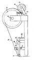
- a wire supply spool (1) is mounted for rotation about a pivot (2).
- a motor (3) is mounted adjacent to the spool (1) and has a rubber wheel (4) which is biassed by a spring (5) into engagement with the spool (1).
- a wire (6) is fed from the spool (1) over a grooved guide wheel (7) to the bonding wedge of a wire bonder (not shown).
- the guide wheel (7) is preferably made of a plastics material and is mounted for free rotation about a bearing on the end of a lever (8) which is mounted on a pivot (9) and biassed by a spring (10).
- the lever (8) can be deflected about the pivot (9) between a first sensor (A) and a second, adjustable sensor (B).
- the guide wheel (7) is pulled down so that the lever (8) activates the sensor (A), which is preferably a light barrier.
- the sensor (A) sends a signal to start the motor (3) which is engaged with the spool (1).
- the motor (3) is started and turns the spool (1) so that wire (6) is supplied, until the lever (8) reaches the sensor (B) and the motor (3) is stopped.
- the position of the sensor (B) can be adjusted as shown by the double-headed arrow to allow for the supply of different amounts of wire.
- the spring loading of the rubber wheel (4) allows for slight variations in the dimensions of the wire supply spool (1).
- the device according to the invention can be used to monitor the amount of wire consumed during a bonding cycle, to determine and indicate any breakages in the wire, and to identify any failures in the supply of wire from the spool.
- the device according to the invention is particularly suitable for monitoring the supply and consumption of relatively thick bonding wire, in particular wire having a diameter of at least 4 mil, more particularly wire having a diameter of from 4 to 20 mil.
Landscapes
- Engineering & Computer Science (AREA)
- Mechanical Engineering (AREA)
- Wire Bonding (AREA)
- Unwinding Of Filamentary Materials (AREA)
Claims (3)
- Vorrichtung zum Einbau in eine Drahtbondmaschine, um die Drahtzuführung von einer Drahtvorlagespule zu einem Bondkeil zu überwachen, wobei die Vorrichtung folgendes aufweist:ein Gestell (2), um eine Drahtvorlagespule (1) drehbar anzubringen;ein Führungsrad (7), das an einem Hebel (8) angebracht ist, wobei der Hebel (8) zwischen einer ersten Position, in die er von einer Feder (10) vorgespannt wird, und einer zweiten Position, in der er einen ersten Sensor (A) aktiviert, auslenkbar ist;einen Motor (3), um die Drahtvorlagespule (1) direkt anzutreiben, wobei der Motor (3) von dem ersten Sensor (A) gestartet wird, wenn der Sensor von dem Hebel (8) aktiviert ist;einen zweiten Sensor (B), der so positioniert ist, daß er von dem Hebel (8) aktiviert wird, um den Motor anzuhalten, wenn eine vorbestimmte Drahtmenge vorgelegt worden ist, wobei der Hebel dann in einer dritten Position auf der entgegengesetzten Seite der ersten Position zu derjenigen der zweiten Position ist;wobei der Draht (6) über das Führungsrad (7) zwischen der Drahtvorlagespule (1) und dem Bondkeil so verläuft, daß der Verbrauch von Draht während eines Bondzyklus eine Auslenkung des Hebels (8) aus seiner ersten Position in seine zweite Position bewirkt; undwobei die Position des zweiten Sensors (B) verstellt werden kann, um die Vorlage unterschiedlicher Drahtmengen zu gestatten.
- Vorrichtung nach Anspruch 1, wobei der zweite Sensor zum Anhalten des Motors (3) einen Zeitschalter aufweist.
- Vorrichtung nach Anspruch 1 oder 2, wobei der erste Sensor (A) und/oder der zweite Sensor (B) eine Lichtschranke ist.
Applications Claiming Priority (2)
| Application Number | Priority Date | Filing Date | Title |
|---|---|---|---|
| GB9006000 | 1990-03-16 | ||
| GB9006000A GB9006000D0 (en) | 1990-03-16 | 1990-03-16 | Device for monitoring wire supply and consumption |
Publications (3)
| Publication Number | Publication Date |
|---|---|
| EP0447085A2 EP0447085A2 (de) | 1991-09-18 |
| EP0447085A3 EP0447085A3 (en) | 1994-05-18 |
| EP0447085B1 true EP0447085B1 (de) | 1997-09-10 |
Family
ID=10672757
Family Applications (1)
| Application Number | Title | Priority Date | Filing Date |
|---|---|---|---|
| EP19910301765 Expired - Lifetime EP0447085B1 (de) | 1990-03-16 | 1991-03-04 | Vorrichtung zur Überprüfung von Drahtzufuhr und -verbrauch |
Country Status (5)
| Country | Link |
|---|---|
| EP (1) | EP0447085B1 (de) |
| JP (1) | JPH0774201A (de) |
| AT (1) | ATE158111T1 (de) |
| DE (1) | DE69127563T2 (de) |
| GB (1) | GB9006000D0 (de) |
Families Citing this family (7)
| Publication number | Priority date | Publication date | Assignee | Title |
|---|---|---|---|---|
| CN104085728A (zh) * | 2014-07-09 | 2014-10-08 | 新兴铸管股份有限公司 | 天车钢丝绳更换装置 |
| KR101674029B1 (ko) * | 2015-04-10 | 2016-11-09 | (주) 인선 | 박스 봉합기용 와이어 풀림 장치 및 이를 구비한 박스 봉합기 |
| CN104827174B (zh) * | 2015-04-29 | 2016-10-05 | 张家港市东航机械有限公司 | 一种工字轮焊接装置 |
| CN106185451B (zh) * | 2016-07-20 | 2019-05-31 | 诺克威特种导体(常州)有限公司 | 一种无机械阻力放线装置 |
| CN106629448B (zh) * | 2017-01-20 | 2019-03-26 | 广州吉物保贸易有限公司 | 自动张力缠缆机 |
| CN109761104A (zh) * | 2019-03-21 | 2019-05-17 | 福建浔兴拉链科技股份有限公司 | 一种可收放的拉链码装自动送料装置 |
| US11842978B1 (en) * | 2022-07-15 | 2023-12-12 | Asmpt Singapore Pte. Ltd. | Wire bonding system including a wire biasing tool |
Citations (1)
| Publication number | Priority date | Publication date | Assignee | Title |
|---|---|---|---|---|
| US4763826A (en) * | 1986-05-14 | 1988-08-16 | Kulicke And Soffa Ind., Inc. | Automatic wire feed system |
Family Cites Families (3)
| Publication number | Priority date | Publication date | Assignee | Title |
|---|---|---|---|---|
| US3485426A (en) * | 1967-10-11 | 1969-12-23 | Anthony Apicella | Web tensioning device |
| US3587959A (en) * | 1969-06-02 | 1971-06-28 | Formaster Ltd | Web feeding devices |
| US4572421A (en) * | 1983-09-19 | 1986-02-25 | Storage Technology Partners | Apparatus for feeding wire to a wire bonding mechanism |
-
1990
- 1990-03-16 GB GB9006000A patent/GB9006000D0/en active Pending
-
1991
- 1991-03-04 EP EP19910301765 patent/EP0447085B1/de not_active Expired - Lifetime
- 1991-03-04 DE DE69127563T patent/DE69127563T2/de not_active Expired - Fee Related
- 1991-03-04 AT AT91301765T patent/ATE158111T1/de not_active IP Right Cessation
- 1991-03-13 JP JP4806491A patent/JPH0774201A/ja active Pending
Patent Citations (1)
| Publication number | Priority date | Publication date | Assignee | Title |
|---|---|---|---|---|
| US4763826A (en) * | 1986-05-14 | 1988-08-16 | Kulicke And Soffa Ind., Inc. | Automatic wire feed system |
Also Published As
| Publication number | Publication date |
|---|---|
| JPH0774201A (ja) | 1995-03-17 |
| EP0447085A3 (en) | 1994-05-18 |
| DE69127563D1 (de) | 1997-10-16 |
| ATE158111T1 (de) | 1997-09-15 |
| GB9006000D0 (en) | 1990-05-09 |
| EP0447085A2 (de) | 1991-09-18 |
| DE69127563T2 (de) | 1998-04-02 |
Similar Documents
| Publication | Publication Date | Title |
|---|---|---|
| JP3276421B2 (ja) | 制御システム | |
| US4771930A (en) | Apparatus for supplying uniform tail lengths | |
| KR101596249B1 (ko) | 와이어 본딩 장치 및 반도체 장치의 제조 방법 | |
| EP0447085B1 (de) | Vorrichtung zur Überprüfung von Drahtzufuhr und -verbrauch | |
| US5277354A (en) | Device for monitoring wire supply and consumption | |
| EP0494510B1 (de) | Bondkopf | |
| US5971248A (en) | Steady autorotation of wire bonding capillary | |
| US5318234A (en) | Automatic wire de-spooler for wire bonding machines | |
| KR100392520B1 (ko) | 와이어본딩장치 | |
| JP3724875B2 (ja) | ワイヤーボンディング方法とそのワイヤーボンディング方法を使用した半導体実装方法ならびにワイヤーボンディング装置とそのワイヤーボンディング装置を備えた半導体実装装置。 | |
| KR100609634B1 (ko) | 본딩 장비의 본딩 헤드 | |
| JP3818932B2 (ja) | ワイヤボンディング装置 | |
| CN213278061U (zh) | 新型引线键合线夹及邦定机焊线系统 | |
| GB2270868A (en) | Wire bonding control system. | |
| JPH11312707A (ja) | ワイヤボンディング装置 | |
| JP2000174056A (ja) | ワイヤボンディング装置 | |
| JPH03114239A (ja) | ボンディング面接触検出装置 | |
| JP2024179860A (ja) | ワイヤボンディング装置及びリカバリ方法 | |
| JPS6231134A (ja) | 超音波ワイヤボンディング方法および装置 | |
| JP2904707B2 (ja) | ワイヤフィード量検出方法およびこれを用いたワイヤボンディング装置 | |
| US20040182912A1 (en) | Wire bonder | |
| JPH05154917A (ja) | ワークの加熱・接合方法 | |
| JPS63257238A (ja) | ワイヤボンデイング装置 | |
| Gobel et al. | Quality control for wire bonding | |
| JPS62179733A (ja) | ワイヤボンデイング方式 |
Legal Events
| Date | Code | Title | Description |
|---|---|---|---|
| PUAI | Public reference made under article 153(3) epc to a published international application that has entered the european phase |
Free format text: ORIGINAL CODE: 0009012 |
|
| AK | Designated contracting states |
Kind code of ref document: A2 Designated state(s): AT CH DE ES FR GB IT LI NL SE |
|
| RAP1 | Party data changed (applicant data changed or rights of an application transferred) |
Owner name: F & K DELVOTEC BONDTECHNIK GMBH |
|
| PUAL | Search report despatched |
Free format text: ORIGINAL CODE: 0009013 |
|
| AK | Designated contracting states |
Kind code of ref document: A3 Designated state(s): AT CH DE ES FR GB IT LI NL SE |
|
| 17P | Request for examination filed |
Effective date: 19940607 |
|
| 17Q | First examination report despatched |
Effective date: 19950801 |
|
| GRAG | Despatch of communication of intention to grant |
Free format text: ORIGINAL CODE: EPIDOS AGRA |
|
| GRAH | Despatch of communication of intention to grant a patent |
Free format text: ORIGINAL CODE: EPIDOS IGRA |
|
| GRAH | Despatch of communication of intention to grant a patent |
Free format text: ORIGINAL CODE: EPIDOS IGRA |
|
| GRAA | (expected) grant |
Free format text: ORIGINAL CODE: 0009210 |
|
| AK | Designated contracting states |
Kind code of ref document: B1 Designated state(s): AT CH DE ES FR GB IT LI NL SE |
|
| PG25 | Lapsed in a contracting state [announced via postgrant information from national office to epo] |
Ref country code: IT Free format text: LAPSE BECAUSE OF FAILURE TO SUBMIT A TRANSLATION OF THE DESCRIPTION OR TO PAY THE FEE WITHIN THE PRESCRIBED TIME-LIMIT;WARNING: LAPSES OF ITALIAN PATENTS WITH EFFECTIVE DATE BEFORE 2007 MAY HAVE OCCURRED AT ANY TIME BEFORE 2007. THE CORRECT EFFECTIVE DATE MAY BE DIFFERENT FROM THE ONE RECORDED. Effective date: 19970910 Ref country code: NL Free format text: LAPSE BECAUSE OF FAILURE TO SUBMIT A TRANSLATION OF THE DESCRIPTION OR TO PAY THE FEE WITHIN THE PRESCRIBED TIME-LIMIT Effective date: 19970910 Ref country code: ES Free format text: THE PATENT HAS BEEN ANNULLED BY A DECISION OF A NATIONAL AUTHORITY Effective date: 19970910 |
|
| REF | Corresponds to: |
Ref document number: 158111 Country of ref document: AT Date of ref document: 19970915 Kind code of ref document: T |
|
| REG | Reference to a national code |
Ref country code: CH Ref legal event code: EP |
|
| REF | Corresponds to: |
Ref document number: 69127563 Country of ref document: DE Date of ref document: 19971016 |
|
| ET | Fr: translation filed | ||
| PG25 | Lapsed in a contracting state [announced via postgrant information from national office to epo] |
Ref country code: SE Effective date: 19971210 |
|
| REG | Reference to a national code |
Ref country code: CH Ref legal event code: NV Representative=s name: E. BLUM & CO. PATENTANWAELTE |
|
| NLV1 | Nl: lapsed or annulled due to failure to fulfill the requirements of art. 29p and 29m of the patents act | ||
| PLBE | No opposition filed within time limit |
Free format text: ORIGINAL CODE: 0009261 |
|
| STAA | Information on the status of an ep patent application or granted ep patent |
Free format text: STATUS: NO OPPOSITION FILED WITHIN TIME LIMIT |
|
| 26N | No opposition filed | ||
| PGFP | Annual fee paid to national office [announced via postgrant information from national office to epo] |
Ref country code: AT Payment date: 20010323 Year of fee payment: 11 |
|
| REG | Reference to a national code |
Ref country code: GB Ref legal event code: IF02 |
|
| PG25 | Lapsed in a contracting state [announced via postgrant information from national office to epo] |
Ref country code: AT Free format text: LAPSE BECAUSE OF NON-PAYMENT OF DUE FEES Effective date: 20020304 |
|
| PGFP | Annual fee paid to national office [announced via postgrant information from national office to epo] |
Ref country code: GB Payment date: 20040209 Year of fee payment: 14 |
|
| PGFP | Annual fee paid to national office [announced via postgrant information from national office to epo] |
Ref country code: FR Payment date: 20040318 Year of fee payment: 14 |
|
| PGFP | Annual fee paid to national office [announced via postgrant information from national office to epo] |
Ref country code: CH Payment date: 20040323 Year of fee payment: 14 |
|
| PG25 | Lapsed in a contracting state [announced via postgrant information from national office to epo] |
Ref country code: GB Free format text: LAPSE BECAUSE OF NON-PAYMENT OF DUE FEES Effective date: 20050304 |
|
| PG25 | Lapsed in a contracting state [announced via postgrant information from national office to epo] |
Ref country code: LI Free format text: LAPSE BECAUSE OF NON-PAYMENT OF DUE FEES Effective date: 20050331 Ref country code: CH Free format text: LAPSE BECAUSE OF NON-PAYMENT OF DUE FEES Effective date: 20050331 |
|
| PGFP | Annual fee paid to national office [announced via postgrant information from national office to epo] |
Ref country code: DE Payment date: 20050530 Year of fee payment: 15 |
|
| REG | Reference to a national code |
Ref country code: CH Ref legal event code: PL |
|
| GBPC | Gb: european patent ceased through non-payment of renewal fee |
Effective date: 20050304 |
|
| PG25 | Lapsed in a contracting state [announced via postgrant information from national office to epo] |
Ref country code: FR Free format text: LAPSE BECAUSE OF NON-PAYMENT OF DUE FEES Effective date: 20051130 |
|
| REG | Reference to a national code |
Ref country code: FR Ref legal event code: ST Effective date: 20051130 |
|
| PG25 | Lapsed in a contracting state [announced via postgrant information from national office to epo] |
Ref country code: DE Free format text: LAPSE BECAUSE OF NON-PAYMENT OF DUE FEES Effective date: 20061003 |