EP0447080A1 - Reconnaissance device - Google Patents
Reconnaissance device Download PDFInfo
- Publication number
- EP0447080A1 EP0447080A1 EP91301733A EP91301733A EP0447080A1 EP 0447080 A1 EP0447080 A1 EP 0447080A1 EP 91301733 A EP91301733 A EP 91301733A EP 91301733 A EP91301733 A EP 91301733A EP 0447080 A1 EP0447080 A1 EP 0447080A1
- Authority
- EP
- European Patent Office
- Prior art keywords
- reconnaissance
- image
- reconnaissance device
- flight
- receiving station
- Prior art date
- Legal status (The legal status is an assumption and is not a legal conclusion. Google has not performed a legal analysis and makes no representation as to the accuracy of the status listed.)
- Withdrawn
Links
Images

Classifications
-
- F—MECHANICAL ENGINEERING; LIGHTING; HEATING; WEAPONS; BLASTING
- F41—WEAPONS
- F41G—WEAPON SIGHTS; AIMING
- F41G3/00—Aiming or laying means
- F41G3/02—Aiming or laying means using an independent line of sight
-
- F—MECHANICAL ENGINEERING; LIGHTING; HEATING; WEAPONS; BLASTING
- F42—AMMUNITION; BLASTING
- F42B—EXPLOSIVE CHARGES, e.g. FOR BLASTING, FIREWORKS, AMMUNITION
- F42B12/00—Projectiles, missiles or mines characterised by the warhead, the intended effect, or the material
- F42B12/02—Projectiles, missiles or mines characterised by the warhead, the intended effect, or the material characterised by the warhead or the intended effect
- F42B12/36—Projectiles, missiles or mines characterised by the warhead, the intended effect, or the material characterised by the warhead or the intended effect for dispensing materials; for producing chemical or physical reaction; for signalling ; for transmitting information
- F42B12/365—Projectiles transmitting information to a remote location using optical or electronic means
Definitions
- the present invention relates to a device for tactical reconnaissance and survey.
- An aerial reconnaissance device comprising an elongated body having a flight-arresting device at one end, an image-forming device at the other end, a telemetry package adpated to transmit to a receiving station an image of a scene viewed by the image-forming device and means for deploying the flight-arresting device at a suitable point in the flight path of the reconnaissance device when it is in use.
- the image-forming device preferably is a solid-state television camera which may be adapted to operate in the visual or infra-red regions of the electromagnetic spectrum.
- the telemetry package in addition to being adapted to transmit to a receiving station an image of the scene viewed by the image-forming device, may be adapted also to measure air temperature, wind speed and direction, barometric pressure, and the range of objects in the field of view of the image-forming device.
- the device is in the form of a projectile, most suitably, such that it can be launched from a conventional mortar, although other forms of projectile, or even free-falling devices which can be launched from aircraft, are envisaged.
- the device is particularly advantageous for the device to be in the form of a mortar bomb of-conventional form so that it may be interchangeable with standard rounds of mortar ammunition.
- Such weapons are simple, highly mobile and used by troops in immediate contact with their adversaries.
- mortars are high-angle, low velocity, weapons which would give the reconnaissance devices relatively high apogees without subjecting them to excessively large initial accelerations.
- a reconnaissance device embodying the invention consists of a casing 1 the overall shape and size of which is such that the reconnaissance device is interchangeable with a round of conventional mortar ammunition.
- the casing 1 is in three portions, a nose cone 2, a central main body 3 and a tail assembly 4.
- the complete assembly is adapted to be launched from a trench mortar in the usual way.
- Both the nose cone 2 and the tail assembly 4 are arranged to be separated from the main body 3 of the casing 1 at an appropriate moment in the flight of the reconnaissance device.
- the main body 3 of the casing 1 contains a fuse or other control device arranged to jettison the nose cone 2 and tail assembly 4 when desired; an optical system 6, shown schematically as a lens, and an associated solid-state video camera 7.
- a telemetry package 8 which includes transponders arranged to provide information as to the range of the device from its launching point, its altitude and possibly its orientation, a radio transmitter 9 and power pack 10.
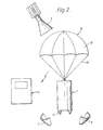
- An antenna for the transmitter 9 is incorporated in the cords 11 and canopy 12 of a parachute 13 which is contained in the tail assembly 4 and deployed when the tail assembly 4 is jettisoned, as shown in Figure 2.
- the optical system 6 is surrounded by a shock-absorbent buffer 14.
- the optical system 6, camera 7 and telemetry package 8 are all protected against shock, both to enable them to withstand the launch forces and to enable the main body 3 of the reconnaissance device to be recovered and re-used. This is particularly important if it is used in a training role.
- the command unit 15 is arranged to produce and display an image of the scene observed by the optical system 6 and its associated camera 7, together with range and bearing information derived from the output of the telemetry package 8.
- a micro-computer contained in the command unit 15 is arranged to compute correction factors to enable the fall of observed live mortar rounds to be ranged onto selected targets. Wind drift may be derived either by telemetry from the reconnaissance device or by measuring the drift of objects in the displayed image of the scene observed by the reconnaissance device.
- the command unit 15 may contain also a pattern-recognition facility to assist in target recognition.
- the command module 15 may include also a short duration recorder to enable scenes observed by the reconnaissance device to be reviewed if desired. Also, signals from the telemetry package 8 related to the orientation of the reconnaissance device, particularly if it is being deliberately spun, may be used in the command module 15 to produce a steady image of constant orientation. Also the computer in the command module 15 may be programmed to produce an image on the display of constant size as the height of the reconnaissance device decreases, which may be to the same scale as standard military maps and/or include a scale bar.
- the reconnaissance device may be stabilised against spinning by means of subsidiary drogues, or by winglets which are deployed at the same time as the parachute 13.
- the optical system 6 may be mounted with its optic axis at an angle to the longitudinal axis of the reconnaissance device and the reconnaissance device made deliberately to rotate so as to enable a larger area to be viewed.
- the same effect could be achieved with a stabilised reconnaissance device by incorporating a scanning mirror in the optical system 6.
- Other optional features which could be included in the optical system 6, are interchargeable lenses of differing focal lengths or a zoom lens operated by signals from the command unit 15.
- the telemetry package 8 also may include detectors arranged to pick up and relay to the command unit 14 radio signals and/or vehicle ignition emissions.
- a modified form of the device which can be used for covert reconnaissance does not deplay a parachute or a balloon but uses air brakes which form part of the casing 1 of the reconnaissance device.
Landscapes
- Engineering & Computer Science (AREA)
- General Engineering & Computer Science (AREA)
- Chemical & Material Sciences (AREA)
- Combustion & Propulsion (AREA)
- Aiming, Guidance, Guns With A Light Source, Armor, Camouflage, And Targets (AREA)
- Toys (AREA)
Abstract
A reconnaissance device (1) comprising, an elongated body (3) having a flight-arresting device at one end, an image-forming device (7) at the other and a telemetry package (9) in the central part of the body of the device. Preferably the device is interchangeable with a standard mortar bomb.
Description
- The present invention relates to a device for tactical reconnaissance and survey.
- Existing methods of tactical reconnaissance and survey involve the use of aircraft, manned or remotely controlled, or mobile reconnaissance units, traditionally light cavalry. Both these methods have disadvantages in that very heavy equipment use is involved and they often cannot respond either quickly enough, or on a sufficiently localised scale, particularly in the case where the military situation is very fluid.
- There is, therefore a need for a highly mobile, inexpensive, preferably expendable, reconnaissance device which is capable of being used by ground troops when in, or about to become in contact with an adversary.
- An aerial reconnaissance device comprising an elongated body having a flight-arresting device at one end, an image-forming device at the other end, a telemetry package adpated to transmit to a receiving station an image of a scene viewed by the image-forming device and means for deploying the flight-arresting device at a suitable point in the flight path of the reconnaissance device when it is in use.
- The image-forming device preferably is a solid-state television camera which may be adapted to operate in the visual or infra-red regions of the electromagnetic spectrum.
- The telemetry package in addition to being adapted to transmit to a receiving station an image of the scene viewed by the image-forming device, may be adapted also to measure air temperature, wind speed and direction, barometric pressure, and the range of objects in the field of view of the image-forming device.
- Preferably the device is in the form of a projectile, most suitably, such that it can be launched from a conventional mortar, although other forms of projectile, or even free-falling devices which can be launched from aircraft, are envisaged.
- It is particularly advantageous for the device to be in the form of a mortar bomb of-conventional form so that it may be interchangeable with standard rounds of mortar ammunition. Such weapons are simple, highly mobile and used by troops in immediate contact with their adversaries. Also, mortars are high-angle, low velocity, weapons which would give the reconnaissance devices relatively high apogees without subjecting them to excessively large initial accelerations.
- The invention will now be described, by way of example, with reference to the accompanying drawings, in which
- Figure 1 is a representation of an embodiment of the invention in the form of a mortar bomb, and
- Figure 2 shows the embodiment of Figure 1 in use.
- Referring to the drawings, a reconnaissance device embodying the invention consists of a
casing 1 the overall shape and size of which is such that the reconnaissance device is interchangeable with a round of conventional mortar ammunition. Thecasing 1 is in three portions, anose cone 2, a central main body 3 and atail assembly 4. The complete assembly is adapted to be launched from a trench mortar in the usual way. Both thenose cone 2 and thetail assembly 4 are arranged to be separated from the main body 3 of thecasing 1 at an appropriate moment in the flight of the reconnaissance device. The main body 3 of thecasing 1 contains a fuse or other control device arranged to jettison thenose cone 2 andtail assembly 4 when desired; an optical system 6, shown schematically as a lens, and an associated solid-state video camera 7. Also contained in the main body 3 of thecasing 1 is atelemetry package 8 which includes transponders arranged to provide information as to the range of the device from its launching point, its altitude and possibly its orientation, a radio transmitter 9 andpower pack 10. An antenna for the transmitter 9 is incorporated in thecords 11 andcanopy 12 of aparachute 13 which is contained in thetail assembly 4 and deployed when thetail assembly 4 is jettisoned, as shown in Figure 2. The optical system 6 is surrounded by a shock-absorbent buffer 14. - The optical system 6, camera 7 and
telemetry package 8 are all protected against shock, both to enable them to withstand the launch forces and to enable the main body 3 of the reconnaissance device to be recovered and re-used. This is particularly important if it is used in a training role. - Signals from the transmitter 9 are received at a man-
portable command unit 15. Thecommand unit 15 is arranged to produce and display an image of the scene observed by the optical system 6 and its associated camera 7, together with range and bearing information derived from the output of thetelemetry package 8. A micro-computer contained in thecommand unit 15 is arranged to compute correction factors to enable the fall of observed live mortar rounds to be ranged onto selected targets. Wind drift may be derived either by telemetry from the reconnaissance device or by measuring the drift of objects in the displayed image of the scene observed by the reconnaissance device. Thecommand unit 15 may contain also a pattern-recognition facility to assist in target recognition. - The
command module 15 may include also a short duration recorder to enable scenes observed by the reconnaissance device to be reviewed if desired. Also, signals from thetelemetry package 8 related to the orientation of the reconnaissance device, particularly if it is being deliberately spun, may be used in thecommand module 15 to produce a steady image of constant orientation. Also the computer in thecommand module 15 may be programmed to produce an image on the display of constant size as the height of the reconnaissance device decreases, which may be to the same scale as standard military maps and/or include a scale bar. - The reconnaissance device may be stabilised against spinning by means of subsidiary drogues, or by winglets which are deployed at the same time as the
parachute 13. Alternatively, the optical system 6 may be mounted with its optic axis at an angle to the longitudinal axis of the reconnaissance device and the reconnaissance device made deliberately to rotate so as to enable a larger area to be viewed. The same effect could be achieved with a stabilised reconnaissance device by incorporating a scanning mirror in the optical system 6. Other optional features which could be included in the optical system 6, are interchargeable lenses of differing focal lengths or a zoom lens operated by signals from thecommand unit 15. Thetelemetry package 8 also may include detectors arranged to pick up and relay to thecommand unit 14 radio signals and/or vehicle ignition emissions. - A modified form of the device which can be used for covert reconnaissance does not deplay a parachute or a balloon but uses air brakes which form part of the
casing 1 of the reconnaissance device.
Claims (9)
- An aerial reconnaissance device comprising an elongated body having a flight-arresting device at one end, an image-forming device at the other end, a telemetry package adpated to transmit to a receiving station an image of a scene viewed by the image-forming device and means for deploying the flight-arresting device at a suitable point in the flight path of the reconnaissance device when it is in use.
- A reconnaissance device according to claim 1 wherein the flight-arresting device is a parachute or balloon.
- A reconnaissance device according to claim 1 or claim 2 wherein the image-forming device is a solid-state television camera.
- A reconnaissance device according to any proceding claim wherein the telemetry package is adapted to measure and transmit information relating to air temperature, wind speed and direction, barometric pressure and the range of objects in the field of view of the image-forming device.
- A reconnaissance device according to any proceding claim wherein the device is adapted to be launched as a projectile.
- A reconnaissance device according to claim 5 wherein the device is adapted to be fired from a mortar.
- A reconnaissance device according to claim 6 wherein the reconnaissance device is adapted to be interchangeable with standard mortar ammunition.
- An aerial reconnaissance device according to any proceding claim in association with a receiving station wherein the receiving station is adapted to display an image of the scene observed by the reconnaissance device and other parameters transmitted by the telemetry package.
- An aerial reconnaissance device according to claim 8 wherein the receiving station includes means for recording the image of the scene observed by the image-forming device and the other parameters transmitted by the telemetry package.
Applications Claiming Priority (2)
| Application Number | Priority Date | Filing Date | Title |
|---|---|---|---|
| GB909005457A GB9005457D0 (en) | 1990-03-10 | 1990-03-10 | Reconnaissance device |
| GB9005457 | 1990-03-10 |
Publications (1)
| Publication Number | Publication Date |
|---|---|
| EP0447080A1 true EP0447080A1 (en) | 1991-09-18 |
Family
ID=10672428
Family Applications (1)
| Application Number | Title | Priority Date | Filing Date |
|---|---|---|---|
| EP91301733A Withdrawn EP0447080A1 (en) | 1990-03-10 | 1991-03-11 | Reconnaissance device |
Country Status (3)
| Country | Link |
|---|---|
| EP (1) | EP0447080A1 (en) |
| FI (1) | FI911139A (en) |
| GB (2) | GB9005457D0 (en) |
Cited By (16)
| Publication number | Priority date | Publication date | Assignee | Title |
|---|---|---|---|---|
| EP0738866A2 (en) * | 1995-04-17 | 1996-10-23 | Hughes Missile Systems Company | Piggyback bomb damage assessment system |
| EP0738867A2 (en) * | 1995-04-17 | 1996-10-23 | Hughes Missile Systems Company | All-aspect bomb damage assessment system |
| FR2794231A1 (en) * | 1999-02-19 | 2000-12-01 | Rheinmetall W & M Gmbh | RECOGNITION PROBE |
| EP1225413A1 (en) * | 2001-01-08 | 2002-07-24 | Oerlikon Contraves Gesellschaft mit beschränkter Haftung | Method for inherent target reconnaissance |
| EP1391681A1 (en) * | 2002-08-20 | 2004-02-25 | Diehl Munitionssysteme GmbH & Co. KG | Method and device for real time ground reconnaissance |
| EP1413899A2 (en) * | 2002-10-24 | 2004-04-28 | Diehl Munitionssysteme GmbH & Co. KG | Method of determining the height distribution of horizontal wind speed |
| FR2860623A1 (en) * | 2003-10-06 | 2005-04-08 | Mbda France | METHOD FOR TAKING PICTURES ON BOARD OF A ROTATING FLYING BODY AND SYSTEM IMPLEMENTING SAID METHOD |
| WO2006001856A2 (en) | 2004-03-15 | 2006-01-05 | Georgia Tech Research Corporation | A projectile and system for providing air-to-surface reconnaissance |
| WO2009010171A1 (en) * | 2007-07-18 | 2009-01-22 | Rheinmetall Waffe Munition Gmbh | Sub-munition unit |
| WO2010027538A1 (en) * | 2008-08-27 | 2010-03-11 | Raytheon Company | Unmanned surveillance vehicle |
| JP2010085040A (en) * | 2008-10-01 | 2010-04-15 | Ihi Aerospace Co Ltd | Impact observation system |
| DE102009023388A1 (en) | 2009-05-29 | 2010-12-02 | Diehl Bgt Defence Gmbh & Co. Kg | Reconnaissance projectile for use in reconnaissance mechanism, has supporting device provided at front section of cartridge-like housing, where front section is supportable at distance against base |
| JP2012007804A (en) * | 2010-06-24 | 2012-01-12 | Yokogawa Denshikiki Co Ltd | Projection type flying body |
| GB2537832A (en) * | 2015-04-26 | 2016-11-02 | Perez-Llabata Alejandro | P.I.v2 weather balloon shuttle |
| US9725172B2 (en) | 2012-01-03 | 2017-08-08 | Bae Systems Plc | Surveillance system |
| RU215774U1 (en) * | 2022-06-29 | 2022-12-26 | Федеральное государственное казенное военное образовательное учреждение высшего образования "ВОЕННАЯ АКАДЕМИЯ МАТЕРИАЛЬНО-ТЕХНИЧЕСКОГО ОБЕСПЕЧЕНИЯ имени генерала армии А.В. Хрулева" Министерства обороны Российской Федерации | AMMUNITION WITH COMBINED DETECTION AND TARGET MODES FOR 82-mm MORTAR |
Families Citing this family (2)
| Publication number | Priority date | Publication date | Assignee | Title |
|---|---|---|---|---|
| US5432546A (en) * | 1992-12-21 | 1995-07-11 | Enel Company | Weapon impact assessment system |
| RU2771508C1 (en) * | 2021-05-04 | 2022-05-05 | Федеральное государственное казенное военное образовательное учреждение высшего образования "ВОЕННАЯ АКАДЕМИЯ МАТЕРИАЛЬНО-ТЕХНИЧЕСКОГО ОБЕСПЕЧЕНИЯ имени генерала армии А.В. Хрулева" | Ammunition with a combination of detection and target destruction modes for an underbarrel grenade launcher |
Citations (7)
| Publication number | Priority date | Publication date | Assignee | Title |
|---|---|---|---|---|
| GB1284487A (en) * | 1970-02-24 | 1972-08-09 | Mullard Ltd | Improvements in or relating to scanning and imaging systems |
| US3962537A (en) * | 1975-02-27 | 1976-06-08 | The United States Of America As Represented By The Secretary Of The Navy | Gun launched reconnaissance system |
| US4112753A (en) * | 1977-05-09 | 1978-09-12 | Call David B | Meteorological measuring apparatus |
| US4267562A (en) * | 1977-10-18 | 1981-05-12 | The United States Of America As Represented By The Secretary Of The Army | Method of autonomous target acquisition |
| FR2541444A1 (en) * | 1982-06-25 | 1984-08-24 | Thomson Csf | Remote-detection device of the mine type and firing system comprising such devices |
| US4481514A (en) * | 1982-03-09 | 1984-11-06 | Beukers Laboratories, Inc. | Microprocessor based radiosonde |
| JPS63169200A (en) * | 1987-01-06 | 1988-07-13 | Tech Res & Dev Inst Of Japan Def Agency | Constructing method for large capacity communication network for emergency use |
Family Cites Families (7)
| Publication number | Priority date | Publication date | Assignee | Title |
|---|---|---|---|---|
| GB1031393A (en) * | 1961-09-22 | 1966-06-02 | British Aircraft Corp Ltd | Improved means for guiding a missile |
| GB1188651A (en) * | 1962-03-05 | 1970-04-22 | British Aircraft Corp Ltd | Improvements in or relating to Missiles |
| NL125606C (en) * | 1962-11-09 | |||
| GB1258044A (en) * | 1967-11-02 | 1971-12-22 | ||
| US3487781A (en) * | 1967-12-20 | 1970-01-06 | Susquehanna Corp | Nose cone ejection for payloads employing parachutes |
| CH591672A5 (en) * | 1974-03-12 | 1977-09-30 | Precitronic | |
| GB2051319B (en) * | 1979-11-15 | 1983-01-26 | Baj Vickers Ltd | Rockets |
-
1990
- 1990-03-10 GB GB909005457A patent/GB9005457D0/en active Pending
-
1991
- 1991-03-01 GB GB9104404A patent/GB2244118A/en not_active Withdrawn
- 1991-03-07 FI FI911139A patent/FI911139A/en not_active Application Discontinuation
- 1991-03-11 EP EP91301733A patent/EP0447080A1/en not_active Withdrawn
Patent Citations (7)
| Publication number | Priority date | Publication date | Assignee | Title |
|---|---|---|---|---|
| GB1284487A (en) * | 1970-02-24 | 1972-08-09 | Mullard Ltd | Improvements in or relating to scanning and imaging systems |
| US3962537A (en) * | 1975-02-27 | 1976-06-08 | The United States Of America As Represented By The Secretary Of The Navy | Gun launched reconnaissance system |
| US4112753A (en) * | 1977-05-09 | 1978-09-12 | Call David B | Meteorological measuring apparatus |
| US4267562A (en) * | 1977-10-18 | 1981-05-12 | The United States Of America As Represented By The Secretary Of The Army | Method of autonomous target acquisition |
| US4481514A (en) * | 1982-03-09 | 1984-11-06 | Beukers Laboratories, Inc. | Microprocessor based radiosonde |
| FR2541444A1 (en) * | 1982-06-25 | 1984-08-24 | Thomson Csf | Remote-detection device of the mine type and firing system comprising such devices |
| JPS63169200A (en) * | 1987-01-06 | 1988-07-13 | Tech Res & Dev Inst Of Japan Def Agency | Constructing method for large capacity communication network for emergency use |
Non-Patent Citations (1)
| Title |
|---|
| PATENT ABSTRACTS OF JAPAN, vol. 12, nr. 435 (E-683),13th July 1988; & JP-A-63 169 200 (SASAKI TATSURO) 06-01-1987 * |
Cited By (30)
| Publication number | Priority date | Publication date | Assignee | Title |
|---|---|---|---|---|
| EP0738867A2 (en) * | 1995-04-17 | 1996-10-23 | Hughes Missile Systems Company | All-aspect bomb damage assessment system |
| EP0738866A3 (en) * | 1995-04-17 | 1998-11-04 | Raytheon Company | Piggyback bomb damage assessment system |
| EP0738867A3 (en) * | 1995-04-17 | 1998-11-04 | Raytheon Company | All-aspect bomb damage assessment system |
| EP0738866A2 (en) * | 1995-04-17 | 1996-10-23 | Hughes Missile Systems Company | Piggyback bomb damage assessment system |
| FR2794231A1 (en) * | 1999-02-19 | 2000-12-01 | Rheinmetall W & M Gmbh | RECOGNITION PROBE |
| EP1225413A1 (en) * | 2001-01-08 | 2002-07-24 | Oerlikon Contraves Gesellschaft mit beschränkter Haftung | Method for inherent target reconnaissance |
| EP1391681A1 (en) * | 2002-08-20 | 2004-02-25 | Diehl Munitionssysteme GmbH & Co. KG | Method and device for real time ground reconnaissance |
| EP1413899A3 (en) * | 2002-10-24 | 2006-03-08 | Diehl BGT Defence GmbH & Co.KG | Method of determining the height distribution of horizontal wind speed |
| EP1413899A2 (en) * | 2002-10-24 | 2004-04-28 | Diehl Munitionssysteme GmbH & Co. KG | Method of determining the height distribution of horizontal wind speed |
| JP2007514116A (en) * | 2003-10-06 | 2007-05-31 | エムべーデーアー フランス | Method for taking a picture on a flying rotator and system for implementing this method |
| US7672480B2 (en) | 2003-10-06 | 2010-03-02 | Mbda France | Method for photographing on board of a flying rotating body and system for carrying out said method |
| NO340449B1 (en) * | 2003-10-06 | 2017-04-24 | Mbda France | Method and system of photography from an object in spin in an airway |
| EP1522960A1 (en) * | 2003-10-06 | 2005-04-13 | MBDA France | Image acquisition process on board a rotating flying body and associated system |
| CN1864174B (en) * | 2003-10-06 | 2013-03-27 | Mbda法国公司 | Image acquisition process on board a rotating flying body and associated system |
| FR2860623A1 (en) * | 2003-10-06 | 2005-04-08 | Mbda France | METHOD FOR TAKING PICTURES ON BOARD OF A ROTATING FLYING BODY AND SYSTEM IMPLEMENTING SAID METHOD |
| WO2005036458A1 (en) * | 2003-10-06 | 2005-04-21 | Mbda France | Method for photographing on board of a flying rotating body and system for carrying out said method |
| EP1761431A2 (en) * | 2004-03-15 | 2007-03-14 | Georgia Technology Research Corporation | A projectile and system for providing air-to-surface reconnaissance |
| EP1761431A4 (en) * | 2004-03-15 | 2010-09-22 | Georgia Tech Res Inst | A projectile and system for providing air-to-surface reconnaissance |
| WO2006001856A2 (en) | 2004-03-15 | 2006-01-05 | Georgia Tech Research Corporation | A projectile and system for providing air-to-surface reconnaissance |
| WO2009010171A1 (en) * | 2007-07-18 | 2009-01-22 | Rheinmetall Waffe Munition Gmbh | Sub-munition unit |
| WO2010027538A1 (en) * | 2008-08-27 | 2010-03-11 | Raytheon Company | Unmanned surveillance vehicle |
| JP2012501431A (en) * | 2008-08-27 | 2012-01-19 | レイセオン カンパニー | Unmanned surveillance vehicle |
| US8263919B2 (en) | 2008-08-27 | 2012-09-11 | Raytheon Company | Unmanned surveillance vehicle |
| JP2010085040A (en) * | 2008-10-01 | 2010-04-15 | Ihi Aerospace Co Ltd | Impact observation system |
| DE102009023388A1 (en) | 2009-05-29 | 2010-12-02 | Diehl Bgt Defence Gmbh & Co. Kg | Reconnaissance projectile for use in reconnaissance mechanism, has supporting device provided at front section of cartridge-like housing, where front section is supportable at distance against base |
| JP2012007804A (en) * | 2010-06-24 | 2012-01-12 | Yokogawa Denshikiki Co Ltd | Projection type flying body |
| US9725172B2 (en) | 2012-01-03 | 2017-08-08 | Bae Systems Plc | Surveillance system |
| GB2537832A (en) * | 2015-04-26 | 2016-11-02 | Perez-Llabata Alejandro | P.I.v2 weather balloon shuttle |
| RU215774U1 (en) * | 2022-06-29 | 2022-12-26 | Федеральное государственное казенное военное образовательное учреждение высшего образования "ВОЕННАЯ АКАДЕМИЯ МАТЕРИАЛЬНО-ТЕХНИЧЕСКОГО ОБЕСПЕЧЕНИЯ имени генерала армии А.В. Хрулева" Министерства обороны Российской Федерации | AMMUNITION WITH COMBINED DETECTION AND TARGET MODES FOR 82-mm MORTAR |
| RU216613U1 (en) * | 2022-08-03 | 2023-02-15 | Федеральное государственное казенное военное образовательное учреждение высшего образования "Военная академия материально-технического обеспечения имени генерала армии А.В. Хрулёва" Министерства обороны Российской Федерации | ARTILLERY SHELL FOR AERO-VIDEO INTELLIGENCE |
Also Published As
| Publication number | Publication date |
|---|---|
| FI911139A (en) | 1991-09-11 |
| FI911139A0 (en) | 1991-03-07 |
| GB2244118A (en) | 1991-11-20 |
| GB9104404D0 (en) | 1991-04-17 |
| GB9005457D0 (en) | 1990-10-10 |
Similar Documents
| Publication | Publication Date | Title |
|---|---|---|
| US12013212B2 (en) | Multimode unmanned aerial vehicle | |
| US11940251B2 (en) | Remotely controllable aeronautical ordnance | |
| EP0447080A1 (en) | Reconnaissance device | |
| US3962537A (en) | Gun launched reconnaissance system | |
| EP2871438B1 (en) | Rocket or artillery launched smart reconnaissance pod | |
| US7679037B2 (en) | Personal rifle-launched reconnaisance system | |
| JP2878639B2 (en) | Bomb damage assessment system for all phases | |
| US9725172B2 (en) | Surveillance system | |
| US5186414A (en) | Hybrid data link | |
| EP1761431A2 (en) | A projectile and system for providing air-to-surface reconnaissance | |
| US6244535B1 (en) | Man-packable missile weapon system | |
| JPH0710091A (en) | Sighting apparatus of aircraft | |
| US5432546A (en) | Weapon impact assessment system | |
| US6510776B2 (en) | Immediate battle damage assessment of missile attack effectiveness | |
| IL143694A (en) | Projectile fuse imaging device and method | |
| AU2020201173B2 (en) | Multimode unmanned aerial vehicle | |
| RU2776005C1 (en) | Method for forming target image to ensure use of tactical guided missiles with optoelectronic homing head | |
| RU2247312C1 (en) | Method for check-up of results of target destruction | |
| Culver | Military Applications Of Fiber Optic Tethered Vehicle Technology | |
| Eldridge | New technologies in range optical tracking systems | |
| HAF et al. | Close Air Support Thermo-Optical Rocket 70 (CASTOR-70) Preliminary Concept Development |
Legal Events
| Date | Code | Title | Description |
|---|---|---|---|
| PUAI | Public reference made under article 153(3) epc to a published international application that has entered the european phase |
Free format text: ORIGINAL CODE: 0009012 |
|
| AK | Designated contracting states |
Kind code of ref document: A1 Designated state(s): BE DE ES FR IT SE |
|
| STAA | Information on the status of an ep patent application or granted ep patent |
Free format text: STATUS: THE APPLICATION IS DEEMED TO BE WITHDRAWN |
|
| 18D | Application deemed to be withdrawn |
Effective date: 19920319 |