EP0447075A2 - Optische Faser mit verbesserter Biegefestigkeit - Google Patents
Optische Faser mit verbesserter Biegefestigkeit Download PDFInfo
- Publication number
- EP0447075A2 EP0447075A2 EP91301700A EP91301700A EP0447075A2 EP 0447075 A2 EP0447075 A2 EP 0447075A2 EP 91301700 A EP91301700 A EP 91301700A EP 91301700 A EP91301700 A EP 91301700A EP 0447075 A2 EP0447075 A2 EP 0447075A2
- Authority
- EP
- European Patent Office
- Prior art keywords
- index
- optical fiber
- core
- refraction
- cladding
- Prior art date
- Legal status (The legal status is an assumption and is not a legal conclusion. Google has not performed a legal analysis and makes no representation as to the accuracy of the status listed.)
- Granted
Links
- 239000013307 optical fiber Substances 0.000 title claims abstract description 68
- 238000005253 cladding Methods 0.000 claims abstract description 72
- 230000000994 depressogenic effect Effects 0.000 claims abstract description 22
- 239000000835 fiber Substances 0.000 claims description 57
- 239000002243 precursor Substances 0.000 claims description 19
- VYPSYNLAJGMNEJ-UHFFFAOYSA-N Silicium dioxide Chemical compound O=[Si]=O VYPSYNLAJGMNEJ-UHFFFAOYSA-N 0.000 claims description 16
- 229910052732 germanium Inorganic materials 0.000 claims description 8
- GNPVGFCGXDBREM-UHFFFAOYSA-N germanium atom Chemical compound [Ge] GNPVGFCGXDBREM-UHFFFAOYSA-N 0.000 claims description 8
- 239000000377 silicon dioxide Substances 0.000 claims description 8
- 239000000463 material Substances 0.000 claims description 7
- ZOXJGFHDIHLPTG-UHFFFAOYSA-N Boron Chemical compound [B] ZOXJGFHDIHLPTG-UHFFFAOYSA-N 0.000 claims 1
- KRHYYFGTRYWZRS-UHFFFAOYSA-M Fluoride anion Chemical compound [F-] KRHYYFGTRYWZRS-UHFFFAOYSA-M 0.000 claims 1
- OAICVXFJPJFONN-UHFFFAOYSA-N Phosphorus Chemical compound [P] OAICVXFJPJFONN-UHFFFAOYSA-N 0.000 claims 1
- 229910052796 boron Inorganic materials 0.000 claims 1
- 229910052698 phosphorus Inorganic materials 0.000 claims 1
- 239000011574 phosphorus Substances 0.000 claims 1
- 230000009977 dual effect Effects 0.000 abstract description 7
- 239000011162 core material Substances 0.000 description 42
- 238000005452 bending Methods 0.000 description 17
- 239000006185 dispersion Substances 0.000 description 14
- 230000003287 optical effect Effects 0.000 description 12
- 238000004891 communication Methods 0.000 description 8
- 230000007423 decrease Effects 0.000 description 8
- 238000013461 design Methods 0.000 description 5
- 239000011248 coating agent Substances 0.000 description 4
- 238000000576 coating method Methods 0.000 description 4
- 238000000034 method Methods 0.000 description 4
- 239000005304 optical glass Substances 0.000 description 4
- 230000000694 effects Effects 0.000 description 3
- 238000012360 testing method Methods 0.000 description 3
- YCKRFDGAMUMZLT-UHFFFAOYSA-N Fluorine atom Chemical compound [F] YCKRFDGAMUMZLT-UHFFFAOYSA-N 0.000 description 2
- 230000002411 adverse Effects 0.000 description 2
- 230000003247 decreasing effect Effects 0.000 description 2
- 238000000151 deposition Methods 0.000 description 2
- 229910052731 fluorine Inorganic materials 0.000 description 2
- 239000011737 fluorine Substances 0.000 description 2
- 239000003365 glass fiber Substances 0.000 description 2
- 238000004519 manufacturing process Methods 0.000 description 2
- 238000013459 approach Methods 0.000 description 1
- 230000005540 biological transmission Effects 0.000 description 1
- 238000005229 chemical vapour deposition Methods 0.000 description 1
- 239000004020 conductor Substances 0.000 description 1
- 230000008021 deposition Effects 0.000 description 1
- 229920006240 drawn fiber Polymers 0.000 description 1
- BHEPBYXIRTUNPN-UHFFFAOYSA-N hydridophosphorus(.) (triplet) Chemical compound [PH] BHEPBYXIRTUNPN-UHFFFAOYSA-N 0.000 description 1
- 230000007774 longterm Effects 0.000 description 1
- 238000004806 packaging method and process Methods 0.000 description 1
- 238000004321 preservation Methods 0.000 description 1
- 230000000644 propagated effect Effects 0.000 description 1
- 230000001902 propagating effect Effects 0.000 description 1
- 238000009877 rendering Methods 0.000 description 1
- 230000035945 sensitivity Effects 0.000 description 1
- 238000004088 simulation Methods 0.000 description 1
- 238000004804 winding Methods 0.000 description 1
Images


Classifications
-
- G—PHYSICS
- G02—OPTICS
- G02B—OPTICAL ELEMENTS, SYSTEMS OR APPARATUS
- G02B6/00—Light guides; Structural details of arrangements comprising light guides and other optical elements, e.g. couplings
-
- G—PHYSICS
- G02—OPTICS
- G02B—OPTICAL ELEMENTS, SYSTEMS OR APPARATUS
- G02B6/00—Light guides; Structural details of arrangements comprising light guides and other optical elements, e.g. couplings
- G02B6/02—Optical fibres with cladding with or without a coating
- G02B6/036—Optical fibres with cladding with or without a coating core or cladding comprising multiple layers
- G02B6/03616—Optical fibres characterised both by the number of different refractive index layers around the central core segment, i.e. around the innermost high index core layer, and their relative refractive index difference
- G02B6/03638—Optical fibres characterised both by the number of different refractive index layers around the central core segment, i.e. around the innermost high index core layer, and their relative refractive index difference having 3 layers only
- G02B6/03655—Optical fibres characterised both by the number of different refractive index layers around the central core segment, i.e. around the innermost high index core layer, and their relative refractive index difference having 3 layers only arranged - + +
-
- G—PHYSICS
- G02—OPTICS
- G02B—OPTICAL ELEMENTS, SYSTEMS OR APPARATUS
- G02B6/00—Light guides; Structural details of arrangements comprising light guides and other optical elements, e.g. couplings
- G02B6/02—Optical fibres with cladding with or without a coating
- G02B6/02004—Optical fibres with cladding with or without a coating characterised by the core effective area or mode field radius
- G02B6/02009—Large effective area or mode field radius, e.g. to reduce nonlinear effects in single mode fibres
Definitions
- This invention relates to an optical fiber having enhanced bend resistance.
- optical fiber After only a somewhat recent introduction, optical fiber has had a meteoric rise as the predominant means of transmission media in voice and data communications.
- Optical fiber is manufactured by drawing glass fiber from an optical glass preform which is made by any of several well known processes. Afterwards, or as part of a tandem process, the drawn fiber is coated, cured, measured and taken up, desirably in an automatic take up apparatus, on a spool to provide a package.
- an optical glass fiber has a diameter on the order of 125 microns, for example, and is covered with a coating material which increases the outer diameter of the coated fiber to about 250 microns, for example.
- the glass fiber includes a core having a diameter of about 6.2 microns and a cladding system having a diameter of about 125 microns.
- the cladding system comprises inner and outer claddings. At least the outer portion of the cladding system is the precursor tube in which have been deposited materials to provide the core and the inner cladding when the tube is collapsed to form a preform.
- optical fiber package is used in operations such as ribboning, cabling, and rewinding and is used to ship optical fiber to other companies which further process the fiber.
- the optical fiber typically is used in voice and data communications systems, both commercial and military.
- the package may be used in weapons systems in which it is used for guidance and for data communications.
- Such uses include communication lines between aircraft, between in aircraft and a ship, and between a projectile, such as a missile, and a control station at a launch site, for example.
- Optical fiber provides the advantages of increased data bandwidth, reduced weight and greater range than wire-guided systems of the prior art.
- a typical optical fiber application in a weapons systems involves the packaging of a continuous length of optical fiber on a bobbin which is positioned inside a vehicle.
- a vehicle commonly is referred to as a tethered vehicle.
- optical fiber is payed out from a bobbin in the tethered vehicle.
- One end of the fiber is attached to operational devices in the vehicle, whereas the other end of the fiber is connected to a control or communications station at a launch site. During and after launch, two-way communication with the vehicle is conducted.
- optical fiber is less robust than metallic conductors, rendering it subject to breakage. Aside from breakage, optical fiber communication performance may be degraded by microbends, which are totally determined by mode field radius, and macrobends in the fiber which are generated by bending or by other stresses to which the fiber may be subjected. Such damage to an optical fiber not only reduces the long-term durability of the fiber, but also causes losses in the strengh and in the content of the optical signal. Likewise, physical or optical integrity may be affected adversely by any sharp bends which are experienced as the fiber pays out at exceptionally high speeds from its packaged configuration. In this usage, the tiber undergoes severe bending. In fact the bending radius may be on the order of a few millimeters. What is needed is an optical fiber that is resistant to small bends. Prior art single mode fiber normally has not been sufficiently bend resistant for deployment in tethered vehicles.
- optical fiber which is suitable for use in tethered vehicle applications. It should be one which is easily manufacturable and which provides acceptable optical and mechanical performance notwithstanding its subjection to severe bending during payout.
- optical fiber of this invention an object of which is to inhibit macrobending.
- the optical fiber of this invention has a relatively large mode field radius but is effective in reducing loss in macrobending.
- An optical fiber of this invention has a circular shaped cross section transverse to its longitudinal axis and includes a doped core and a cladding system adjacent to the core.
- the cladding system includes an inner cladding and a first outer cladding.
- a second outer cladding is provided by a precursor silica tube in which materials have been deposited and which form the core and the inner cladding when the preform tube is collapsed to provide a preform from which the optical fiber is drawn.
- a refractive index profile of the core and the cladding system has a W-shaped configuration with a ⁇ which is the difference between the indices of refraction of the core and of a depressed inner cladding thereof expressed as a percentage of the index of refraction of the tube being at least 0.9% and a cutoff wavelength of less than 1500 nm.
- the optical fiber includes a germanium doped core having a ⁇ + which is the difference between the index of refraction of the core and the index of refraction of a precursor tube expressed as a percentage of the index of refraction of the precursor tube of at least 0.6%.
- the optical fiber includes a cladding adjacent to the core being down doped and having an inner depressed portion thereof having a difference between the index of refraction of the precursor tube and the index of refraction of the depressed inner cladding expressed as a percentage of the index of refraction of the precursor tube ( ⁇ ) being about 0.3%.
- the outer diameter of the inner depressed cladding portion is in the range of about the product of two to four and the diameter of the core.
- the first outer cladding has an index which is within about 0.1% of the refractive index of the precursor silica tube from which the fiber is drawn.
- the germanium doped core has a ⁇ + of 0.9%.
- the ⁇ + which characterizes the core is 0.6%.
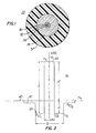
- FIG. 1 there is shown a single mode optical fiber 22 of this invention.
- the optical fiber 22 of this invention which is characterized by a W-shaped refractive index configuration shown in FIG. 2 is suitable for winding on a bobbin 25 for use in a tethered vehicle (see FIG. 3).
- a package 26 of the optical fiber 22 is mounted in a vehicle 27.
- An end of the optical tiber is connected to ground control equipement 28.
- the ground control equipment is used to control the flight pattern of the vehicle.
- the optical fiber 22 has been made by depositing glassy material within a silica precursor tube.
- the silica precursor tube is characterized by an index of refraction, n t (see FIG. 2). Following deposition, the tube is collapsed and fiber is drawn therefrom.
- the optical fiber 22 includes an optical glass portion comprising a core 30, an inner cladding 32 having an index of refraction, n cli , which is depressed (see FIG. 2) from that of the precursor tube, a first outer cladding 34 having an index of refraction n clo and an outer cladding 35 which is provided by the collapsed precursor tube and which is referred to as the outer tube cladding or second outer cladding.
- the optical glass portion is enclosed in a coating system 37 comprising one or more layers of coating materials.
- the core 30 has a diameter of about 6.2 microns
- the inner depressed cladding 32 has an outer diameter of about 15.5 microns
- the first outer cladding has an outer diameter of about 31 microns.
- the second outer tube cladding has an outer diameter of 125 microns.
- the outer diameter of the coating system typically is about 250 microns.
- the optical fiber 22 to be used as a tethered vehicle fiber should be characterized by minimal small radius bending loss while being capable of causing the increase in initial loss to a be held to a minimum at the same time single mode operation needs to be maintained. This could be accomplished by containing the fundamental mode without containing the second order mode.
- microbends Small perturbations in the axis of an optical fiber which are referred to as microbends can cause optical loss by allowing power to escape through the cladding.
- the degree of confinement of the optical power and thus the susceptibility to microbending-induced optical loss can be characterized by the spot size, also referred to as the mode field diameter, and the effective index of the fundamental propagating mode. These parameters are well known in the art.
- Critical parameters which affect microbending and macrobending loss are the diameter, d, of the core and the difference in the indices of refraction, n c and n cli , of the core and the inner cladding, respectively. This difference generally is expressed as a percentage difference of the index of refraction of precursor tube, n t , and is designated ⁇ .
- d the diameter of the core 30, and ⁇ , determine, at a given wavelength, the spot size and the effective index.
- a small spot size and high effective index assure tight confinement of the optical power to the region of the fiber core and thus high resistance to microbending and macrobending induced loss.
- the dependence of the spot size and zero dispersion wavelength on ⁇ is less pronounced.
- an optical fiber having a relatively high ⁇ may be used to provide macrobending resistance, while maintaining a spot size which is suitable for low loss splicing.
- increasing ⁇ to improve the macrobending performance will increase the cutoff wavelength, ⁇ c , of the fiber.
- the cutoff wavelength is that wavelength below which higher order modes may be propagated. Inasmuch as the bandwidth of the fiber is drastically reduced if higher order modes are present, any increase in cutoff wavelength must be controlled to preserve single mode operation at the system wavelength. If ⁇ c is higher, the optical fiber is more bend resistant and most power is concentrated in the core.
- modified W optical fiber of this invention which has been found to be ideally suited for use in tethered vehicles.
- the optical fiber of this invention is characterized by an inner cladding 32 (see FIG. 1) having an index of refraction which is depressed relative to that of the outer cladding 34 and of the outer tube cladding 35 (see FIG. 2). Such a fiber is said to have a depressed inner cladding.
- the core 30 has a diameter, d, and an index of refraction n c , represented by a line 44 which has a relative refractive index difference ⁇ + with respect to a reference line 45 corresponding to the index of refraction n t of the outer tube cladding 35 and expressed as a percentage of the index of refraction of the precursor tube.
- the inner cladding 32 has a diameter, D, and an index of refraction n cli which is represented by a line designated by the numeral 43 and which has a relative refractive index difference ⁇ with respect to the same reference line 45 expressed as a percentage of the index of refraction of the precursor tube.
- the overall difference in index of refraction from that of the core to that of the inner depressed cladding expressed as a percentage of the index of refraction of the precursor tube is designated ⁇ .
- ratios of ⁇ / ⁇ and D/d which are appropriate to provide a cutoff wavelength which is substantially reduced from that of a matched cladding fiber with the same core size and overall refractive index difference. What is provided is a substantially microbending and macrobending insensitive fiber capable of operation in single mode fashion at a predetermined wavelength.
- W-design optical fiber is known in the prior art. For example, see an article entitled “Low Loss Dual Window Single Mode Fibers With Very Low Bending Sensitivity" authored by B. J. Ainslie, et al. and published at page 317 in the IOOC-ECOC '85 Technical Digest. In the Ainslie article, for a reported W fiber, the height of the core refractive index above the inner dressed cladding expressed in terms of ⁇ is 0.0069.
- such a ⁇ value is insufficient to provide the bend resistance required for use in a tethered vehicle. Instead it has been found that a ⁇ of at least 0.009 is needed for such usage. Further, such fiber is characterized by a ⁇ + of at least 0.6% for ⁇ equal to 0.3%. Of course, ⁇ could be increased as could ⁇ +. Desired is a larger ⁇ which means ⁇ + can be smaller and there is less germanium in the core. As a result, the intrinsic loss is lower. The deeper the depression of the inner cladding in the refractive index profile, the better the mode power confinement. However, the manufacturing process limits the depth of it to about 0.3% to 0.4%.
- the optical fiber of this invention is suitable for two windows of operation, one for a dual window of 1310 and 1550 and the second for the 1550 window only.
- the optical fiber is characterized by a ⁇ + of 0.9% and ⁇ is about 0.3%.
- the optical fiber is characterized by a ⁇ + of 0.6% and ⁇ is about 0.3%.
- Beside optical requirements, high strength and long length are also important for fiber to be used in tethered vehicles.
- Long length implies that the new fiber design should allow for easy manufacture from a large preform. All these requirements are met by the optical fiber of this invention.
- the radius of the depressed region is relatively small.
- the radius to an outer point "b" (see FIG. 2) of the depressed inner cladding is equal to the product of about 2.5 and the radius to the outer point "a” (see FIG. 2) of the core.
- the radius to the outer point of the depressed inner cladding 32 is equal to the product of 2.5 and a number ranging from about 3.0 to 3.2 microns.
- the radius to the outer point of the depressed inner cladding is equal to the product of 2.5 and a number ranging from about 4 to 4.3 microns.
- the signal rate of a tethered vehicle system may be no more than a few hundred MHz. Chromatic dispersion should not be a limiting factor to the system with appropriate laser diode transmitters. Again, depending on the system design, the fiber's cutoff wavelength requirement could either be less than 1300 nm for dual window systems or less than 1500 nm for use only at the 1500 nm window.
- the first outer cladding has an index n clo represented by a line 47 which is within about 0.1% of the refractive index of the precursor silica tube, i.e. the reference refractive index, that index of the first outer cladding could be outside this range, if the diameter of the inner cladding were reduced.
- the cutoff wavelength desirably increases.
- ⁇ is at least 0.9% and the cutoff wavelength is less that 1500 nm.
- What is desired and what is accomplished with the W-design fiber of this invention is to contain the fundamental mode without containing the second order mode.
- Preforms were made using the modified chemical vapor deposition (MCVD) technique, with silica tubes as the starting tubes.
- MCVD modified chemical vapor deposition
- Step index germanium doped cores with two different ⁇ + values were made to study the effect on fiber loss and bending properties.
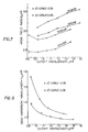
- FIG. 5 A graph of measured cutoff wavelength, ⁇ c versus estimated core radius for two preforms is shown in FIG. 5. As can be seen, the cutoff wavelength increases linearly with core radius. The higher slope corresponds to a preform having the higher core index.
- Macrobending loss result at 1550 nm of ten spools of optical fiber were carried out with a single loop loss test. As the cutoff wavelength approached 1550 nm, the bending performance improved significantly.
- the effect of the core index can be seen in FIG. 6 which shows 2 mm loop radius bending losses plotted against cutoff wavelength for fibers from two preforms. For the same cutoff wavelength, the fiber with the higher core index had lower bending loss.
- the advantage of the fiber of this invention is clear when it is compared with prior art commercially available fiber. With the same cutoff wavelength ( ⁇ c no greater than 1300 nm), fibers of this invention had lower bending loss than prior art fiber.
- both fibers have lower positive index ⁇ + than some prior art fiber, a fiber which has bending performance similar to the prior art fiber, but lower initial loss, could be used. It also follows from this FIG. 6 that if the cutoff wavelength can be increased to 1500 nm, then core index ⁇ + can be reduced still further to lower the initial loss while maintaining superior bending performance.
- the zero dispersion wavelengths of the W-fiber of this invention were found to be lower than other prior art fibers for the same cutoff wavelength. As shown in FIG. 8, for fiber drawn from the same preform, the zero dispersion wavelengths will decrease as cutoff wavelengths increase. These results are consistent with macrobending loss results. When cutoff wavelength increases, the fundamental mode power is more confined in the core region. This reduces waveguide dispersion and the zero dispersion wavelength approaches that of the core material. Consequently, dispersion at 1550 nm will increase as macrobending loss decreases.
Landscapes
- Physics & Mathematics (AREA)
- General Physics & Mathematics (AREA)
- Optics & Photonics (AREA)
- Glass Compositions (AREA)
- Manufacture, Treatment Of Glass Fibers (AREA)
- Optical Fibers, Optical Fiber Cores, And Optical Fiber Bundles (AREA)
- Light Guides In General And Applications Therefor (AREA)
Applications Claiming Priority (2)
| Application Number | Priority Date | Filing Date | Title |
|---|---|---|---|
| US493059 | 1990-03-09 | ||
| US07/493,059 US5032001A (en) | 1990-03-09 | 1990-03-09 | Optical fiber having enhanced bend resistance |
Publications (3)
| Publication Number | Publication Date |
|---|---|
| EP0447075A2 true EP0447075A2 (de) | 1991-09-18 |
| EP0447075A3 EP0447075A3 (en) | 1992-07-15 |
| EP0447075B1 EP0447075B1 (de) | 1996-05-29 |
Family
ID=23958737
Family Applications (1)
| Application Number | Title | Priority Date | Filing Date |
|---|---|---|---|
| EP91301700A Expired - Lifetime EP0447075B1 (de) | 1990-03-09 | 1991-03-01 | Optische Faser mit verbesserter Biegefestigkeit |
Country Status (9)
| Country | Link |
|---|---|
| US (1) | US5032001A (de) |
| EP (1) | EP0447075B1 (de) |
| JP (1) | JPH04219705A (de) |
| KR (1) | KR100249751B1 (de) |
| AU (1) | AU628719B2 (de) |
| CA (1) | CA2036745C (de) |
| DE (1) | DE69119806T2 (de) |
| DK (1) | DK0447075T3 (de) |
| TW (1) | TW217444B (de) |
Cited By (7)
| Publication number | Priority date | Publication date | Assignee | Title |
|---|---|---|---|---|
| RU2168190C2 (ru) * | 1995-11-17 | 2001-05-27 | Корнинг Инкорпорейтед | Оптический волновод с положительной дисперсией |
| RU2172506C2 (ru) * | 1995-11-21 | 2001-08-20 | Корнинг Инкорпорейтед | Усовершенствованный оптический волновод со сдвигом дисперсии |
| WO2003107054A1 (en) * | 2002-06-14 | 2003-12-24 | 3M Innovative Properties Company | Dual-band bend tolerance optical waveguide |
| WO2004113978A1 (en) * | 2003-06-19 | 2004-12-29 | Corning Incorporated | Single polarization optical fiber and system and method for producing same |
| US7130516B2 (en) | 2004-08-31 | 2006-10-31 | 3M Innovative Properties Company | Triple-band bend tolerant optical waveguide |
| US7130515B2 (en) | 2004-08-31 | 2006-10-31 | 3M Innovative Properties Company | Triple-band bend tolerant optical waveguide |
| US7200309B2 (en) | 2003-06-19 | 2007-04-03 | Corning Incorporated | Single polarization and polarization maintaining optical fibers and system utilizing same |
Families Citing this family (42)
| Publication number | Priority date | Publication date | Assignee | Title |
|---|---|---|---|---|
| US5175785A (en) * | 1991-05-02 | 1992-12-29 | Ensign-Bickford Optical Technologies, Inc. | Optical waveguides having reduced bending loss and method of making the same |
| US5329607A (en) * | 1992-02-28 | 1994-07-12 | The United States Of America As Represented By The Secretary Of The Navy | Pure-silica core dual-mode optical fiber |
| US5278931A (en) * | 1992-12-31 | 1994-01-11 | Corning Incorporated | Low bend loss singlemode optical waveguide fiber |
| DE4312121B4 (de) * | 1993-04-14 | 2004-04-15 | CCS Technology, Inc., Wilmington | Optisches Kabel mit mehreren in einer vorgegebenen Struktur angeordneten Lichtwellenleitern |
| US5461692A (en) * | 1993-11-30 | 1995-10-24 | Amoco Corporation | Multimode optical fiber coupling apparatus and method of transmitting laser radiation using same |
| JPH07261048A (ja) * | 1994-03-23 | 1995-10-13 | Sumitomo Electric Ind Ltd | 分散補償ファイバ |
| FR2724234B1 (fr) | 1994-09-05 | 1997-01-03 | Alcatel Fibres Optiques | Fibre optique monomode a dispersion decalee |
| US5835655A (en) * | 1995-01-26 | 1998-11-10 | Corning Incorporated | Large effective area waveguide fiber |
| BR9500990A (pt) * | 1995-03-28 | 1995-08-01 | Abc Algar | Guia de onda ótico |
| US7656578B2 (en) * | 1997-03-21 | 2010-02-02 | Imra America, Inc. | Microchip-Yb fiber hybrid optical amplifier for micro-machining and marking |
| US7576909B2 (en) * | 1998-07-16 | 2009-08-18 | Imra America, Inc. | Multimode amplifier for amplifying single mode light |
| US5852690A (en) * | 1997-06-30 | 1998-12-22 | Minnesota Mining And Manufacturing Company | Depressed cladding fiber design for reducing coupling to cladding modes in fiber gratings |
| EP1020741A4 (de) * | 1997-10-02 | 2005-12-21 | Sumitomo Electric Industries | Dispersionsverschobene optische faser |
| US6275512B1 (en) | 1998-11-25 | 2001-08-14 | Imra America, Inc. | Mode-locked multimode fiber laser pulse source |
| JP2001021735A (ja) * | 1999-07-06 | 2001-01-26 | Shin Etsu Chem Co Ltd | シングルモード光ファイバ母材の選択方法 |
| WO2002031553A2 (en) * | 2000-10-11 | 2002-04-18 | Corning Incorporated | Single mode optical waveguide fiber with reduced dispersion |
| US6603909B2 (en) | 2000-11-21 | 2003-08-05 | 3M Innovative Properties Company | Laser pigtail fiber with inherent attenuation characteristic |
| US6490398B2 (en) * | 2001-02-21 | 2002-12-03 | Fitel Usa Corp. | Dispersion-compensating fiber having a high figure of merit |
| JP2003114350A (ja) * | 2001-07-31 | 2003-04-18 | Furukawa Electric Co Ltd:The | 光ファイバ、光ファイバ部品および光伝送方法 |
| JP2003279780A (ja) * | 2002-01-15 | 2003-10-02 | Sumitomo Electric Ind Ltd | 光ファイバ、光ファイバテープ、光ケーブル及び光ファイバ付き光コネクタ |
| US6771865B2 (en) * | 2002-03-20 | 2004-08-03 | Corning Incorporated | Low bend loss optical fiber and components made therefrom |
| US7280730B2 (en) * | 2004-01-16 | 2007-10-09 | Imra America, Inc. | Large core holey fibers |
| US7209619B2 (en) | 2004-12-30 | 2007-04-24 | Imra America, Inc. | Photonic bandgap fibers |
| US7787729B2 (en) * | 2005-05-20 | 2010-08-31 | Imra America, Inc. | Single mode propagation in fibers and rods with large leakage channels |
| US7272289B2 (en) * | 2005-09-30 | 2007-09-18 | Corning Incorporated | Low bend loss optical fiber |
| FR2893149B1 (fr) | 2005-11-10 | 2008-01-11 | Draka Comteq France | Fibre optique monomode. |
| FR2899693B1 (fr) * | 2006-04-10 | 2008-08-22 | Draka Comteq France | Fibre optique monomode. |
| US7450813B2 (en) * | 2006-09-20 | 2008-11-11 | Imra America, Inc. | Rare earth doped and large effective area optical fibers for fiber lasers and amplifiers |
| CN103246014B (zh) * | 2007-09-26 | 2015-12-23 | Imra美国公司 | 玻璃大芯径光纤 |
| US9042695B2 (en) * | 2007-10-05 | 2015-05-26 | Optacore D.O.O. Optical Fibers | Low bending loss multimode fiber transmission system |
| EP2206001B1 (de) * | 2007-11-09 | 2014-04-16 | Draka Comteq B.V. | Auf mikroebene biegesteife glasfaser |
| US8213077B2 (en) | 2008-04-22 | 2012-07-03 | Imra America, Inc. | Multi-clad optical fibers |
| FR2930997B1 (fr) | 2008-05-06 | 2010-08-13 | Draka Comteq France Sa | Fibre optique monomode |
| WO2010065788A1 (en) * | 2008-12-04 | 2010-06-10 | Imra America, Inc. | Highly rare-earth-doped optical fibers for fiber lasers and amplifiers |
| DE102011009242B4 (de) * | 2010-11-04 | 2020-09-03 | J-Plasma Gmbh | Lichtwellenleiter und Halbzeug zur Herstellung eines Lichtwellenleiters mit biegeoptimierten Eigenschaften |
| CN102156323B (zh) * | 2011-05-05 | 2012-06-06 | 长飞光纤光缆有限公司 | 一种单模光纤 |
| CN102998742B (zh) * | 2012-12-13 | 2014-04-09 | 长飞光纤光缆股份有限公司 | 一种小模场抗弯曲单模光纤 |
| US8818160B2 (en) | 2013-01-18 | 2014-08-26 | Np Photonics, Inc. | IR supercontinuum source using low-loss heavy metal oxide glasses |
| CN103149630B (zh) * | 2013-03-06 | 2016-02-24 | 长飞光纤光缆股份有限公司 | 一种低衰减单模光纤 |
| KR102319301B1 (ko) | 2014-05-20 | 2021-10-28 | 니폰 제온 가부시키가이샤 | 전기 화학 소자 전극용 복합 입자 및 전기 화학 소자 전극용 복합 입자의 제조 방법 |
| US9874686B2 (en) * | 2015-05-29 | 2018-01-23 | Corning Incorporated | Optical fiber with macrobend loss mitigating layer |
| EP3457183B1 (de) * | 2016-05-12 | 2020-06-10 | Sumitomo Electric Industries, Ltd. | Mehradrige glasfaser, faser-bragg-gitter und verfahren zur herstellung eines faser-bragg-gitters |
Family Cites Families (10)
| Publication number | Priority date | Publication date | Assignee | Title |
|---|---|---|---|---|
| US4435040A (en) * | 1981-09-03 | 1984-03-06 | Bell Telephone Laboratories, Incorporated | Double-clad optical fiberguide |
| US4715679A (en) * | 1981-12-07 | 1987-12-29 | Corning Glass Works | Low dispersion, low-loss single-mode optical waveguide |
| US4691990A (en) * | 1984-11-13 | 1987-09-08 | American Telephone And Telegraph Company, At&T Bell Laboratories | Optical fiber with depressed index outer cladding |
| US4641917A (en) * | 1985-02-08 | 1987-02-10 | At&T Bell Laboratories | Single mode optical fiber |
| JPS6237361A (ja) * | 1985-08-09 | 1987-02-18 | Sumitomo Metal Ind Ltd | 溶融金属めつき法および装置 |
| US4836640A (en) * | 1986-06-27 | 1989-06-06 | American Telephone And Telegraph Company, At&T Bell Laboratories | Depressed cladding optical fiber cable |
| US4770492A (en) * | 1986-10-28 | 1988-09-13 | Spectran Corporation | Pressure or strain sensitive optical fiber |
| JPS63208003A (ja) * | 1987-02-25 | 1988-08-29 | Sumitomo Electric Ind Ltd | 光フアイバ |
| AU8276687A (en) * | 1987-10-29 | 1989-05-23 | Spectran Corporation | Pressure or strain sensitive optical fiber |
| US4838643A (en) * | 1988-03-23 | 1989-06-13 | Alcatel Na, Inc. | Single mode bend insensitive fiber for use in fiber optic guidance applications |
-
1990
- 1990-03-09 US US07/493,059 patent/US5032001A/en not_active Expired - Lifetime
-
1991
- 1991-02-20 CA CA002036745A patent/CA2036745C/en not_active Expired - Fee Related
- 1991-02-28 AU AU72016/91A patent/AU628719B2/en not_active Ceased
- 1991-03-01 DK DK91301700.0T patent/DK0447075T3/da active
- 1991-03-01 DE DE69119806T patent/DE69119806T2/de not_active Expired - Fee Related
- 1991-03-01 EP EP91301700A patent/EP0447075B1/de not_active Expired - Lifetime
- 1991-03-02 KR KR1019910003424A patent/KR100249751B1/ko not_active Expired - Fee Related
- 1991-03-07 JP JP3065310A patent/JPH04219705A/ja active Pending
- 1991-07-10 TW TW080105367A patent/TW217444B/zh active
Cited By (11)
| Publication number | Priority date | Publication date | Assignee | Title |
|---|---|---|---|---|
| RU2168190C2 (ru) * | 1995-11-17 | 2001-05-27 | Корнинг Инкорпорейтед | Оптический волновод с положительной дисперсией |
| RU2172506C2 (ru) * | 1995-11-21 | 2001-08-20 | Корнинг Инкорпорейтед | Усовершенствованный оптический волновод со сдвигом дисперсии |
| RU2172507C2 (ru) * | 1996-02-23 | 2001-08-20 | Корнинг Инкорпорейтед | Одномодовый оптический волновод с большой эффективной площадью |
| WO2003107054A1 (en) * | 2002-06-14 | 2003-12-24 | 3M Innovative Properties Company | Dual-band bend tolerance optical waveguide |
| US6947652B2 (en) | 2002-06-14 | 2005-09-20 | 3M Innovative Properties Company | Dual-band bend tolerant optical waveguide |
| WO2004113978A1 (en) * | 2003-06-19 | 2004-12-29 | Corning Incorporated | Single polarization optical fiber and system and method for producing same |
| US7194172B2 (en) | 2003-06-19 | 2007-03-20 | Corning Incorporated | Single polarization optical fiber and system and method for producing same |
| US7200309B2 (en) | 2003-06-19 | 2007-04-03 | Corning Incorporated | Single polarization and polarization maintaining optical fibers and system utilizing same |
| CN100388030C (zh) * | 2003-06-19 | 2008-05-14 | 康宁股份有限公司 | 单偏振光纤和系统以及其制造方法 |
| US7130516B2 (en) | 2004-08-31 | 2006-10-31 | 3M Innovative Properties Company | Triple-band bend tolerant optical waveguide |
| US7130515B2 (en) | 2004-08-31 | 2006-10-31 | 3M Innovative Properties Company | Triple-band bend tolerant optical waveguide |
Also Published As
| Publication number | Publication date |
|---|---|
| DK0447075T3 (da) | 1996-07-08 |
| EP0447075A3 (en) | 1992-07-15 |
| TW217444B (de) | 1993-12-11 |
| US5032001A (en) | 1991-07-16 |
| CA2036745A1 (en) | 1991-09-10 |
| DE69119806D1 (de) | 1996-07-04 |
| CA2036745C (en) | 1997-04-01 |
| JPH04219705A (ja) | 1992-08-10 |
| KR910017207A (ko) | 1991-11-05 |
| AU628719B2 (en) | 1992-09-17 |
| AU7201691A (en) | 1991-09-12 |
| EP0447075B1 (de) | 1996-05-29 |
| DE69119806T2 (de) | 1996-10-02 |
| KR100249751B1 (ko) | 2000-03-15 |
Similar Documents
| Publication | Publication Date | Title |
|---|---|---|
| EP0447075B1 (de) | Optische Faser mit verbesserter Biegefestigkeit | |
| US9671553B2 (en) | Bend-resistant multimode optical fiber | |
| US8565568B2 (en) | Broad-bandwidth multimode optical fiber having reduced bending losses | |
| US8340488B2 (en) | Multimode optical fiber | |
| AU613455B2 (en) | Bend insensitive optical fibre | |
| US8520993B2 (en) | Multimode optical fiber having improved bending losses | |
| US8406593B2 (en) | Multimode optical fiber with low bending losses and reduced cladding effect | |
| US8483535B2 (en) | High-bandwidth, dual-trench-assisted multimode optical fiber | |
| US8428410B2 (en) | High-bandwidth multimode optical fiber having reduced bending losses | |
| US8385704B2 (en) | High-bandwidth multimode optical fiber with reduced cladding effect | |
| US8644664B2 (en) | Broad-bandwidth optical fiber | |
| US8867879B2 (en) | Single-mode optical fiber | |
| US8891074B2 (en) | Multimode optical fiber insensitive to bending losses | |
| US8639079B2 (en) | Multimode optical fiber | |
| US8879878B2 (en) | Multimode optical fiber | |
| US9869814B2 (en) | Hybrid single-mode and multimode optical fiber | |
| EP0674193A2 (de) | Optisches Übertragungssystem mit dispersionskompensierter optischer Faser | |
| GB2118321A (en) | Low loss single mode fiber | |
| EP4254028A1 (de) | Für flachbandkabel geeignete einmodenglasfaser | |
| US20250180841A1 (en) | Optical fiber having thin coating diameter without increased microbend sensitivity | |
| Hale et al. | Single Fibre Cable For Dispensing Applications |
Legal Events
| Date | Code | Title | Description |
|---|---|---|---|
| PUAI | Public reference made under article 153(3) epc to a published international application that has entered the european phase |
Free format text: ORIGINAL CODE: 0009012 |
|
| AK | Designated contracting states |
Kind code of ref document: A2 Designated state(s): DE DK FR GB NL |
|
| PUAL | Search report despatched |
Free format text: ORIGINAL CODE: 0009013 |
|
| AK | Designated contracting states |
Kind code of ref document: A3 Designated state(s): DE DK FR GB NL |
|
| 17P | Request for examination filed |
Effective date: 19921207 |
|
| RAP3 | Party data changed (applicant data changed or rights of an application transferred) |
Owner name: AT&T CORP. |
|
| 17Q | First examination report despatched |
Effective date: 19940706 |
|
| GRAH | Despatch of communication of intention to grant a patent |
Free format text: ORIGINAL CODE: EPIDOS IGRA |
|
| GRAA | (expected) grant |
Free format text: ORIGINAL CODE: 0009210 |
|
| AK | Designated contracting states |
Kind code of ref document: B1 Designated state(s): DE DK FR GB NL |
|
| ET | Fr: translation filed | ||
| REF | Corresponds to: |
Ref document number: 69119806 Country of ref document: DE Date of ref document: 19960704 |
|
| REG | Reference to a national code |
Ref country code: DK Ref legal event code: T3 |
|
| PLBE | No opposition filed within time limit |
Free format text: ORIGINAL CODE: 0009261 |
|
| STAA | Information on the status of an ep patent application or granted ep patent |
Free format text: STATUS: NO OPPOSITION FILED WITHIN TIME LIMIT |
|
| 26N | No opposition filed | ||
| PG25 | Lapsed in a contracting state [announced via postgrant information from national office to epo] |
Ref country code: NL Effective date: 19971001 |
|
| NLV4 | Nl: lapsed or anulled due to non-payment of the annual fee |
Effective date: 19971001 |
|
| PGFP | Annual fee paid to national office [announced via postgrant information from national office to epo] |
Ref country code: DK Payment date: 19981221 Year of fee payment: 9 |
|
| PG25 | Lapsed in a contracting state [announced via postgrant information from national office to epo] |
Ref country code: DK Free format text: LAPSE BECAUSE OF NON-PAYMENT OF DUE FEES Effective date: 20000301 |
|
| REG | Reference to a national code |
Ref country code: DK Ref legal event code: EBP |
|
| REG | Reference to a national code |
Ref country code: GB Ref legal event code: IF02 |
|
| PGFP | Annual fee paid to national office [announced via postgrant information from national office to epo] |
Ref country code: GB Payment date: 20040225 Year of fee payment: 14 |
|
| PGFP | Annual fee paid to national office [announced via postgrant information from national office to epo] |
Ref country code: FR Payment date: 20040318 Year of fee payment: 14 |
|
| PGFP | Annual fee paid to national office [announced via postgrant information from national office to epo] |
Ref country code: DE Payment date: 20040430 Year of fee payment: 14 |
|
| PG25 | Lapsed in a contracting state [announced via postgrant information from national office to epo] |
Ref country code: GB Free format text: LAPSE BECAUSE OF NON-PAYMENT OF DUE FEES Effective date: 20050301 |
|
| PG25 | Lapsed in a contracting state [announced via postgrant information from national office to epo] |
Ref country code: DE Free format text: LAPSE BECAUSE OF NON-PAYMENT OF DUE FEES Effective date: 20051001 |
|
| GBPC | Gb: european patent ceased through non-payment of renewal fee |
Effective date: 20050301 |
|
| PG25 | Lapsed in a contracting state [announced via postgrant information from national office to epo] |
Ref country code: FR Free format text: LAPSE BECAUSE OF NON-PAYMENT OF DUE FEES Effective date: 20051130 |
|
| REG | Reference to a national code |
Ref country code: FR Ref legal event code: ST Effective date: 20051130 |