EP0447048A2 - Methode und Vorrichtung zum Messen von Objekten wie Schraubverschluss mit oder ohne Gewinde - Google Patents
Methode und Vorrichtung zum Messen von Objekten wie Schraubverschluss mit oder ohne Gewinde Download PDFInfo
- Publication number
- EP0447048A2 EP0447048A2 EP91301432A EP91301432A EP0447048A2 EP 0447048 A2 EP0447048 A2 EP 0447048A2 EP 91301432 A EP91301432 A EP 91301432A EP 91301432 A EP91301432 A EP 91301432A EP 0447048 A2 EP0447048 A2 EP 0447048A2
- Authority
- EP
- European Patent Office
- Prior art keywords
- fastener
- dimensions
- gage
- cross
- recorded data
- Prior art date
- Legal status (The legal status is an assumption and is not a legal conclusion. Google has not performed a legal analysis and makes no representation as to the accuracy of the status listed.)
- Granted
Links
Images
Classifications
-
- G—PHYSICS
- G01—MEASURING; TESTING
- G01B—MEASURING LENGTH, THICKNESS OR SIMILAR LINEAR DIMENSIONS; MEASURING ANGLES; MEASURING AREAS; MEASURING IRREGULARITIES OF SURFACES OR CONTOURS
- G01B7/00—Measuring arrangements characterised by the use of electric or magnetic techniques
- G01B7/28—Measuring arrangements characterised by the use of electric or magnetic techniques for measuring contours or curvatures
- G01B7/282—Measuring arrangements characterised by the use of electric or magnetic techniques for measuring contours or curvatures for measuring roundness
-
- G—PHYSICS
- G01—MEASURING; TESTING
- G01B—MEASURING LENGTH, THICKNESS OR SIMILAR LINEAR DIMENSIONS; MEASURING ANGLES; MEASURING AREAS; MEASURING IRREGULARITIES OF SURFACES OR CONTOURS
- G01B7/00—Measuring arrangements characterised by the use of electric or magnetic techniques
- G01B7/28—Measuring arrangements characterised by the use of electric or magnetic techniques for measuring contours or curvatures
- G01B7/284—Measuring arrangements characterised by the use of electric or magnetic techniques for measuring contours or curvatures of screw-threads
Definitions
- This invention is directed to a method and apparatus for gaging bodies and is particularly concerned with an improved method and apparatus for gaging threaded fasteners and/or fastener blanks.
- Such gaging is preferably carried out in order to determine deviations of the dimensions of such fasteners and/or blanks from the specified or desired dimensions, which data may be utilized for statistical in-process control, for lot control and the like. While the method and apparatus of the invention may be utilized with both round body and poly-arcuate or lobular bodied fasteners and their blanks, as well as other similar bodies such as round or poly-arcuate pins, shafts, shanks or the like, the ensuing discussion will be directed primarily to the gaging of poly-arcuate or lobular fasteners.
- fastener herein should be understood as including both a fastener blank and a threaded fastener fabricated from such a blank.
- the gaging of lobular fasteners has traditionally been a somewhat complicated task, because the degree of lobulation or out-of-roundness is just as important as the basic thread dimensions in the formation of these fasteners.
- the degree of lobulation, or out of round is usually defined as half the diametral difference between the inscribed and circumscribed circles of a cross-section arcuate form of the fastener.
- Such lobular fasteners are used extensively both as thread-forming screws and for self-locking, or sealing purposes in pre-tapped holes. In either of these general applications control of the degree of lobulation is important in assuring proper performance of the product.
- this degree of lobulation (commonly designated K) must exceed a certain minimum for thread-forming with a reasonable driving effort or for entry into a preformed thread and adequate sealing or self-locking with acceptable driving effort.
- this K or degree of lobulation exceeds a certain maximum amount, the tensile load-carrying ability of the joint in the work may be seriously compromised, due to both the high driving effort required to drive the fastener, as well as the torque and other stresses experienced by the fastener.
- Past methods of gaging the cross-sectional dimensions of lobular thread-forming and self-locking screws used hand micrometers.
- a multi-anvil type micrometer was used, in which the fastener was rotated to obtain the maximum reading; that is, the diameter of the circumscribing circle "C”.
- a more or less conventional micrometer was used to obtain the "D" dimension, which is a cross-section from a high point of one lobe to a low point opposite. It was not the practice, however, to calculate the difference between these two micrometer readings; i.e., the K, or out of round dimension.
- a more particular object is to provide such a method and apparatus which can readily determine the K dimension of a lobular fastener of other lobular bodies or parts.
- a method for gaging fasteners comprises providing gage means for measuring a plurality of diametral cross-sectional dimensions of a fastener; positioning a fastener in surface-to-surface contact with said gage means; recording information corresponding to the dimensions as measured by said gage means during said positioning of said fastener in said surface-to-surface contact therewith, to form recorded data, and ascertaining a predetermined relationship between said dimensions from said recorded data.
- the invention also provides apparatus for carrying out this method.
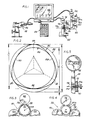
- the apparatus includes at least one gage apparatus or gage means such as a roller-type gage 20, which will be more fully described hereinbelow.
- a second similar roller-type gage 22, also to be more fully discussed hereinbelow is also provided.
- a gage of the type indicated by reference numeral 24 in Fig. 1 might be utilized, although roller-type gages such as gages 20 and 22 are preferred.
- the alternate type gage 24 is of the type referred to as a V-anvil micrometer.
- the method of the invention gages the out of round or so-called K dimension of a fastener which may be a threaded fastener or an unthreaded fastener blank, as the term "fastener" is to be understood, when used hereinafter.
- the fastener may be poly-arcuate or lobular in shape, or round.
- the K dimension may also be referred to as the degree of lobulation.
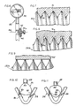
- a trilobular body 30 which may be a fastener blank or a trilobular threaded fastener.
- a trilobular body 30 is indicated generally in Fig. 2.
- An unthreaded trilobular blank, which is designated by reference numeral 30a is shown in Figs.
- the fastener 30b may also be provided with a tapered or conical lead-in surface or tip 35, such as in a thread-forming type of fastener.
- the trilobular body 30 in the example shown in the drawings is placed in surface-to-surface contact with one or both of the gages 20 and 22 shown in Fig. 1 for measuring the dimensions C, E which correspond respectively to diameters of circumscribing and inscribing circles 32, 34 of the trilobular body 30.
- the orientation of a body 30 (which may be blank 30a or threaded fastener 30b) with respect to the gage 20 is indicated in cross-section and somewhat diagrammatically in Fig. 3.
- the engagement of a threaded fastener 30b with the gage 22 is shown in somewhat diagrammatic cross-sectional form in Fig. 4.
- a somewhat enlarged view of the gages 20 and 22 as illustrated in Fig. 1 are found in Fig.
- Figs. 10 and 11 Typical gaging of the circumscribing and inscribing circles for a trilobular body 30 generally with the anvil-type micrometer 24 are shown in Figs. 10 and 11, respectively.
- the ensuing discussion will refer, in additional detail to the gages as illustrated in these respective figures of drawing and to the gaging method of the invention for gaging both threaded and unthreaded fasteners, both of poly-arcuate and round form, as well as similar bodies, to determine out-of-roundness thereof.
- the apparatus and method of the invention proceed by recording data corresponding to the measurements made by the respective gages and ascertaining a predetermined relationship between the inscribed circle and circumscribed circle from this recorded data.
- the means for recording and processing the data is indicated at Fig. 1 as a data-processing unit 26.
- An additional CRT type display 28 may also be coupled with the data-processing unit 26 to display data associated with these measurements.
- a data-processing unit 26 a DATAbank Plus System from Brown & Sharpe, Inc., North Kingstown, R.I.
- Fig. 2 we have discovered that useful statistical data for manufacturing control and batch processing can be obtained by determining the difference between the respective pitch cylinder diameters corresponding to the respective inscribed or inscribing circle 34 (E) and circumscribed or circumscribing circle 32 (C) of a poly-arcuate or lobular body. One-half of this difference constitutes the K or out of round dimension of the body.
- a trilobular body has been illustrated in diametral cross-section in Fig. 2.
- This trilobular body 30 has a geometry as is generally described in U.S. patent to Phipard, No. 3,195,156, for example.
- the trilobular cross-sectional shape will be seen to have three lobes 40, 42, 44 that are separated by arcuate sides 50, 52, 54 such that the lobes generally define an arcuate equilateral triangle.
- the circumscribing circle 32 or diameter C will be seen to form tangents to the three lobes, while the inscribing circle 34 or diameter E forms a tangent to the arcuate sides.
- the circumscribing circle is measured as shown in Fig. 10 by placing the lobes 40, 42 and 44 of the body 30 in contact with the respective three relevant surfaces of the micrometer.
- the micrometer has a generally V-shaped anvil portion 46 and a selectively advanceable and retractable, preferably flat-ended cylindrical spindle member 48.
- the inscribing circle diameter is obtained by placing the arcuate sides 50, 52 and 54 in surface-to-surface contact with the respective flat internal surfaces of the V-shaped anvil 46 and the spindle 48.
- each of the roller-type gages 20, 22 includes a plurality of rollers in a spaced circumferential array about a central axis. While any suitable commercially available gage components may be utilized, we have selected an Electronic Dial Indicator from Brown & Sharpe, Inc., North Kingstown, R.I., and a roller gage from Johnson Gage, Bloomfield, Conn. Alteration of the number and positioning of rollers, as may be required for polygonal or poly-arcuate shapes other than trilobular, is within the scope of the invention.
- rollers 60, 62, 64 and 70, 72, 74 are arrayed at 120° intervals about central axes 65, 75. It will be seen that, when a body 30, (be it threaded fastener 30a or blank 30b) is inserted into each gage, its axis is also coincident with the central gage axis 65, 75.
- the rollers 60, 62 and 64 of gage 20 are arranged with smooth surfaces for contacting an outer surface of the body to be measured, which body may be an unthreaded member such as blank 30a or a threaded fastener such as fastener 30b, as well as being either lobular or round in form. These rollers can measure both the circumscribed circle 32 and the inscribed circle 34 of an outer surface of the body as the body to be measured is rotated therewithin. In the case of a threaded fastener such as fastener 30b, these measurements will yield a measure of the K, or out of round dimension of the outer diameter or thread crest diameters of the fastener.
- an additional gage such as gage 22, which employs grooved rollers 70, 72 and 74, arranged for measuring the C and E dimensions corresponding to the circumscribing and inscribing circles 32, 34 at the pitch line or pitch diameter of the thread.
- This measurement by the use of grooved rollers is illustrated further in Figs. 7 and 8.
- the measurement of the crest or outer diameter of the threads by rollers of the gage 20 is illustrated with respect to roller 62, for example, in Fig. 9. Accordingly, for a threaded fastener two separate out of round or K dimensions will be determined, one for the outer diameter of the thread and one for the pitch line diameter of the thread.
- the rollers 60, 62 and 64 are generally right cylindrical members having smooth continuous surfaces.
- the rollers 70, 72 and 74 are circumferentially grooved.
- These grooves, indicated by reference numeral 80 in Fig. 7, and an alternative groove form indicated by reference numeral 80a in Fig. 8 are shaped to make contact with the threads of a threaded fastener in such a way as to effect the measurement of the C and E dimensions at the pitch line or pitch diameter of the fastener.
- the respective grooves 80 and 80a are further shaped in complementary form to the pitch or shapes of the threads which they are intended to measure at the pitch line.
- the grooves 80 of Fig. 6 are generally tapered in a complementary fashion for entering the threads of the fastener 30b shown therein.
- exemplary fastener 130b of Fig. 8 has a somewhat different thread pitch profile and hence the grooves 80a are somewhat more rectangularly shaped at their inner aspects and convergent at their outer aspects to accommodate this thread-form of fastener 130b.
- the thread form of fastener 130b is generally that described in U.S. patent 4,820,098 to Taubert et al, wherein the flank angle of the thread is on the order of 60° and the flank angle of the thread crests extending beyond the nominal diameter of the screw is on the order of 30°.
- the form of the grooves 80a is varied somewhat to accommodate this sort of thread form.
- the form of the grooves 80, 80a may be further varied as appropriate for any desired thread form angle design without departing from the invention.
- the grooved rollers 70, 72, 74 are shaped to contact the fastener in such a way as to measure the C and E dimensions at the pitch line.
- the actual form of the grooves may be said to be complementary with the thread pitch angle or thread form of the fastener to be so measured.
- suitable direct indicators or indicator means 90, 92 and 94 may also be provided on the respective gages 20, 22 and 24 for a direct read-out of the respective fastener dimensions as they are gaged.
- the method and apparatus of the invention also contemplate measuring the shape or envelope of a tapered, lead in or thread-forming portion 35 (see Figs. 5 and 6) of a thread forming type of fastener. This is preferably accomplished using the roller-type gages 20, 22 as best viewed in Figs. 4 and 5.
- the lead-in portion of the fastener is rotated several full 360° turns within the rollers, thus axially advancing the same somewhat relative to the rollers.
- the data developed in response to this rotation and advancement can be further utilized by the data-processing means 26 to develop data representative of the shape or envelope of the lead-in portion of such a fastener.
- the method of the invention contemplates rotating the fastener 30 substantially 360° and obtaining statistical data therefrom for determining the "aggregate" out-of-round dimension of the fastener.
- the lead threads may be considered to be enveloped or circumscribed within a lobular, frustoconical shape with lobes corresponding in number with those of the body threads.
- the angle of this cone and number of lead threads is governed by the individual product specifications from one fastener to another. However, it will be appreciated that the C and E dimensions will therefore vary from thread to thread, along this tapered lead-in portion.
- the driving effort in the installation of such a thread-rolling or thread-forming screw is generally indicated by the applied torque measured over the degrees of rotation (expressed in radians) of the screw.
- the rotation is accompanied by a progressive radial outward movement of the lead threads with increasing torque in forming complementary internal mating threads in the workpiece or nut. Consequently, the method and apparatus of the invention may also be used in evaluating the relationship of the K or out-of-round dimension to the rotation of the lead threads of such a thread-forming fastener, to assure the same are formed in such a manner as to obtain the desired driving effort and thread forming action.
- the depth of the grooves 80 would be dictated by product specifications, as mentioned above. However, this could be varied up to .325 P (pitch).
- P pitch
- the gage readings will follow the generally undulating pattern of the lobular form with the measured values increasing along a slope generally the same as the slope of the point angle of the lead threads until the body threads of a uniform or constant width or diameter are reached. Accordingly, a measure is obtained of radial penetration of the threads against rotation of the fastener and the gradual formation of complementary internal or mating threads in a workpiece.
- This path of radial penetration versus rotation can be plotted or recorded in appropriate fashion by the data-processing means 26 and for display upon the display means 28.
- the taper of the lead-in portion may also be measured against a desired specification for the product by use of the method and apparatus of the invention.
- roller-type gages over the method using the so-called V-anvil gage as discussed above with reference to Figs. 10 and 11.
- V-anvil gage it is necessary to hold the body to be measured stationary during measurement, and it is necessary to properly and accurately position the body, as shown in Figs. 10 and 11, to obtain the proper dimensional measurements. In practice, this may be done by rotating the body slightly and accepting or recording only the maximum and minimum relative readings as being representative of the respective circumscribed and inscribed circle diameters.
- the invention further contemplates developing statistical data from measurements taken on a plurality of bodies or fasteners, which data may be utilized in lot control or processing control applications.
- the method also contemplates determining from the recorded data points of maximum deviation on the inscribed circle and circumscribed circle diameters of each body or fastener as related to mean measured values thereof.
- the measurement of the out-of-round or K dimension accomplished by the apparatus and method of the invention also effectively results in a measurement of what is normally called the pitch diameter or effective diameter in the case of a threaded fastener.
Landscapes
- Physics & Mathematics (AREA)
- General Physics & Mathematics (AREA)
- Length Measuring Devices With Unspecified Measuring Means (AREA)
- Measurement Of Length, Angles, Or The Like Using Electric Or Magnetic Means (AREA)
- A Measuring Device Byusing Mechanical Method (AREA)
- Forging (AREA)
Applications Claiming Priority (4)
| Application Number | Priority Date | Filing Date | Title |
|---|---|---|---|
| US49461290A | 1990-03-16 | 1990-03-16 | |
| US494612 | 1990-03-16 | ||
| US550701 | 1990-07-10 | ||
| US07/550,701 US5168458A (en) | 1990-03-16 | 1990-07-10 | Method and apparatus for gaging the degree of lobulation of bodies such as threaded fasteners |
Publications (3)
| Publication Number | Publication Date |
|---|---|
| EP0447048A2 true EP0447048A2 (de) | 1991-09-18 |
| EP0447048A3 EP0447048A3 (en) | 1992-02-12 |
| EP0447048B1 EP0447048B1 (de) | 1995-04-19 |
Family
ID=27051468
Family Applications (1)
| Application Number | Title | Priority Date | Filing Date |
|---|---|---|---|
| EP91301432A Expired - Lifetime EP0447048B1 (de) | 1990-03-16 | 1991-02-22 | Methode und Vorrichtung zum Messen von Objekten wie Schraubverschluss mit oder ohne Gewinde |
Country Status (7)
| Country | Link |
|---|---|
| US (1) | US5168458A (de) |
| EP (1) | EP0447048B1 (de) |
| JP (1) | JP3046636B2 (de) |
| BR (1) | BR9101034A (de) |
| CA (1) | CA2036439A1 (de) |
| DE (1) | DE69108966T2 (de) |
| ES (1) | ES2071209T3 (de) |
Families Citing this family (37)
| Publication number | Priority date | Publication date | Assignee | Title |
|---|---|---|---|---|
| US6145207A (en) * | 1998-03-23 | 2000-11-14 | Brunson Instrument Company | Thread pitch diameter measuring system |
| US6286227B1 (en) * | 1998-08-03 | 2001-09-11 | General Electric Company | Micrometer system and process of use therefor |
| US7752266B2 (en) | 2001-10-11 | 2010-07-06 | Ebay Inc. | System and method to facilitate translation of communications between entities over a network |
| JP4677603B2 (ja) * | 2005-08-26 | 2011-04-27 | 株式会社ユタカ | ねじ軸径測定装置 |
| US8639782B2 (en) | 2006-08-23 | 2014-01-28 | Ebay, Inc. | Method and system for sharing metadata between interfaces |
| US7684054B2 (en) * | 2006-08-25 | 2010-03-23 | Gii Acquisition, Llc | Profile inspection system for threaded and axial components |
| US8041150B2 (en) * | 2006-11-29 | 2011-10-18 | The United States Of America As Represented By The Secretary Of Agriculture | Method and apparatus for determining the surface area of a threaded fastener |
| US7812970B2 (en) * | 2007-10-23 | 2010-10-12 | Gii Acquisition, Llc | Method and system for inspecting parts utilizing triangulation |
| US7920278B2 (en) * | 2007-10-23 | 2011-04-05 | Gii Acquisition, Llc | Non-contact method and system for inspecting parts |
| US7738088B2 (en) * | 2007-10-23 | 2010-06-15 | Gii Acquisition, Llc | Optical method and system for generating calibration data for use in calibrating a part inspection system |
| US8237935B2 (en) * | 2007-10-23 | 2012-08-07 | Gii Acquisition, Llc | Method and system for automatically inspecting parts and for automatically generating calibration data for use in inspecting parts |
| US8132802B2 (en) * | 2007-10-23 | 2012-03-13 | Gii Acquisition, Llc | Apparatus for quickly retaining and releasing parts to be optically measured |
| US8550444B2 (en) * | 2007-10-23 | 2013-10-08 | Gii Acquisition, Llc | Method and system for centering and aligning manufactured parts of various sizes at an optical measurement station |
| US7633046B2 (en) * | 2007-10-23 | 2009-12-15 | Gii Acquisition Llc | Method for estimating thread parameters of a part |
| US7633634B2 (en) * | 2007-10-23 | 2009-12-15 | Gii Acquisition, Llc | Optical modules and method of precisely assembling same |
| US7755754B2 (en) * | 2007-10-23 | 2010-07-13 | Gii Acquisition, Llc | Calibration device for use in an optical part measuring system |
| US7738121B2 (en) * | 2007-10-23 | 2010-06-15 | Gii Acquisition, Llc | Method and inspection head apparatus for optically measuring geometric dimensions of a part |
| US7777900B2 (en) * | 2007-10-23 | 2010-08-17 | Gii Acquisition, Llc | Method and system for optically inspecting parts |
| US7796278B2 (en) * | 2008-09-19 | 2010-09-14 | Gii Acquisition, Llc | Method for precisely measuring position of a part to be inspected at a part inspection station |
| US8004694B2 (en) * | 2009-03-27 | 2011-08-23 | Gll Acquistion LLC | System for indirectly measuring a geometric dimension related to an opening in an apertured exterior surface of a part based on direct measurements of the part when fixtured at a measurement station |
| US20130162810A1 (en) * | 2010-09-15 | 2013-06-27 | Nai En Wu | Apparatus for inspecting rotary parts and the method of the inspection |
| US8390826B2 (en) | 2011-04-20 | 2013-03-05 | Gii Acquisition, Llc | Method and system for optically inspecting parts |
| US10094785B2 (en) | 2011-05-17 | 2018-10-09 | Gii Acquisition, Llc | Method and system for optically inspecting headed manufactured parts |
| US9575013B2 (en) | 2011-05-17 | 2017-02-21 | Gii Acquisition, Llc | Non-contact method and system for inspecting a manufactured part at an inspection station having a measurement axis |
| US10088431B2 (en) | 2011-05-17 | 2018-10-02 | Gii Acquisition, Llc | Method and system for optically inspecting headed manufactured parts |
| US9228957B2 (en) | 2013-05-24 | 2016-01-05 | Gii Acquisition, Llc | High speed method and system for inspecting a stream of parts |
| US9372160B2 (en) | 2011-05-17 | 2016-06-21 | Gii Acquisition, Llc | Method and system for optically inspecting the ends of a manufactured part at a single inspection station having a measurement axis |
| US9047657B2 (en) | 2011-05-17 | 2015-06-02 | Gii Acquisition, Lcc | Method and system for optically inspecting outer peripheral surfaces of parts |
| US8570504B2 (en) | 2011-05-17 | 2013-10-29 | Gii Acquisition, Llc | Method and system for optically inspecting parts |
| US9697596B2 (en) | 2011-05-17 | 2017-07-04 | Gii Acquisition, Llc | Method and system for optically inspecting parts |
| US8993914B2 (en) | 2012-12-14 | 2015-03-31 | Gii Acquisition, Llc | High-speed, high-resolution, triangulation-based, 3-D method and system for inspecting manufactured parts and sorting the inspected parts |
| US9486840B2 (en) | 2013-05-24 | 2016-11-08 | Gii Acquisition, Llc | High-speed, triangulation-based, 3-D method and system for inspecting manufactured parts and sorting the inspected parts |
| US9539619B2 (en) | 2013-05-24 | 2017-01-10 | Gii Acquisition, Llc | High speed method and system for inspecting a stream of parts at a pair of inspection stations |
| US10207297B2 (en) | 2013-05-24 | 2019-02-19 | GII Inspection, LLC | Method and system for inspecting a manufactured part at an inspection station |
| US9377297B2 (en) | 2013-08-21 | 2016-06-28 | Gii Acquisition, Llc | High-resolution imaging and processing method and system for increasing the range of a geometric dimension of a part that can be determined |
| US9372077B2 (en) | 2013-08-21 | 2016-06-21 | Gii Acquistion, Llc | High-resolution imaging and processing method and system for determining a geometric dimension of a part |
| US10300510B2 (en) | 2014-08-01 | 2019-05-28 | General Inspection Llc | High speed method and system for inspecting a stream of parts |
Family Cites Families (14)
| Publication number | Priority date | Publication date | Assignee | Title |
|---|---|---|---|---|
| US3879854A (en) * | 1974-07-01 | 1975-04-29 | Johnson Co Gage | Screw thread comparator gaging device having ti-point and segmental gaging means using a single indicator |
| US4064633A (en) * | 1976-03-10 | 1977-12-27 | Wertepny Alexander W | Gauging instrument |
| US4106206A (en) * | 1977-04-25 | 1978-08-15 | The United States Of America As Represented By The Secretary Of The Navy | Positively expandable and retractable thread measuring gage |
| US4490800A (en) * | 1981-12-14 | 1984-12-25 | Powers Manufacturing, Inc. | Dual head gauger apparatus with automatic adjustment for pressure variation |
| US4662074A (en) * | 1982-09-20 | 1987-05-05 | Schweizerische Gesellschaft fur Werkzeugmashinenbau und Fertigungstechnik | Method and apparatus for determining precision of numerically controlled machine tool devices |
| US4736313A (en) * | 1984-02-24 | 1988-04-05 | Mitutoyo Mfg. Co., Ltd. | Digital indication type length measuring system |
| IT1179343B (it) * | 1984-05-28 | 1987-09-16 | Finike Italiana Marposs | Apparecchiatura per controllare la rotondita' di pezzi in rotazione |
| DE3511564A1 (de) * | 1985-03-29 | 1986-10-02 | Hommelwerke GmbH, 7730 Villingen-Schwenningen | Einrichtung zur messung der kreisformabweichung exzentrischer lagerflaechen, insbesondere von pleuellagern |
| FR2593100B1 (fr) * | 1986-01-17 | 1988-03-25 | Snecma | Dispositif de mise a poste d'une piece circulaire. |
| DE3606725A1 (de) * | 1986-03-01 | 1987-09-03 | Skf Gmbh | Verfahren und vorrichtung von durchmesserwerten |
| US4930096A (en) * | 1987-01-22 | 1990-05-29 | Man Design Co., Ltd. | Data-transmitting apparatus having connecting plug |
| DE3708858A1 (de) * | 1987-03-17 | 1988-09-29 | Rissmann Horst G | Vorrichtung zum pruefen und vermessen von gewinden und deren rotationssymmetrischen koaxialen verlauf, sowie deren planlage zu allen anderen durchmessern, flaechen, konen, gewinden und bohrungen an ein und demselben drehteil in einem spannvorgang |
| GB8728016D0 (en) * | 1987-11-30 | 1988-01-06 | Grosvenor R I | Methods and apparatus for measuring transverse dimensions of workpieces |
| JPH02296127A (ja) * | 1989-05-10 | 1990-12-06 | Bridgestone Corp | 空気入りタイヤの欠陥検査方法 |
-
1990
- 1990-07-10 US US07/550,701 patent/US5168458A/en not_active Expired - Lifetime
-
1991
- 1991-02-15 CA CA002036439A patent/CA2036439A1/en not_active Abandoned
- 1991-02-22 DE DE69108966T patent/DE69108966T2/de not_active Expired - Fee Related
- 1991-02-22 EP EP91301432A patent/EP0447048B1/de not_active Expired - Lifetime
- 1991-02-22 ES ES91301432T patent/ES2071209T3/es not_active Expired - Lifetime
- 1991-03-12 JP JP3074036A patent/JP3046636B2/ja not_active Expired - Fee Related
- 1991-03-15 BR BR919101034A patent/BR9101034A/pt not_active IP Right Cessation
Also Published As
| Publication number | Publication date |
|---|---|
| JPH06186026A (ja) | 1994-07-08 |
| JP3046636B2 (ja) | 2000-05-29 |
| CA2036439A1 (en) | 1991-09-17 |
| BR9101034A (pt) | 1991-11-05 |
| DE69108966T2 (de) | 1995-08-24 |
| DE69108966D1 (de) | 1995-05-24 |
| EP0447048B1 (de) | 1995-04-19 |
| ES2071209T3 (es) | 1995-06-16 |
| EP0447048A3 (en) | 1992-02-12 |
| US5168458A (en) | 1992-12-01 |
Similar Documents
| Publication | Publication Date | Title |
|---|---|---|
| EP0447048B1 (de) | Methode und Vorrichtung zum Messen von Objekten wie Schraubverschluss mit oder ohne Gewinde | |
| US5170306A (en) | Method and apparatus for gaging the geometry of point threads and other special threads | |
| EP1835256B1 (de) | Schraubenmessverfahren, Schraubenmesssonde und Schraubenmessgerät mit der Schraubenmesssonde | |
| CN110631534B (zh) | 一种油套管接头锥螺纹中径和螺距的检测方法 | |
| US20100251556A1 (en) | Thread Gauge Checker | |
| CN106052576A (zh) | 螺纹测量装置及测量方法 | |
| US6598305B1 (en) | Spline gage system and method | |
| US20030088991A1 (en) | Single-side measuring devices and methods | |
| US6612042B1 (en) | Thread gage system and method | |
| CN112729039A (zh) | 一种螺纹规用计量校准方法 | |
| AU630540B2 (en) | Method and apparatus for gaging bodies such as threaded fasteners and blanks | |
| JPH02649B2 (de) | ||
| RU2166729C1 (ru) | Способ контроля формы и диаметров внутренних сечений крупногабаритных цилиндрических деталей | |
| US5343624A (en) | Measurement tool | |
| Osanna et al. | Cylindricity—a well known problem and new solutions | |
| JPH0961102A (ja) | ネジプラグゲージ | |
| JPH05332702A (ja) | ボールスクリューの加工精度検査器具 | |
| US2680301A (en) | Pipe thread gauge | |
| US4219938A (en) | Method and means for gauging of threads | |
| EP3088841B1 (de) | Verfahren und einrichtung zur beurteilung der oberflächenbeschaffenheit nach der winkelaufgelösten streulichtmessmethode mit automatischer lageerkennung des werkstücks | |
| CN206095112U (zh) | 一种圆弧螺纹结构检测装置 | |
| CN114440743A (zh) | 一种轴承套圈圆度检测装置及其检测方法 | |
| US5377417A (en) | Thread pitch cylinder gage | |
| CN114964124A (zh) | 一种小型燕尾型榫槽内孔对称度检测装置及方法 | |
| CN222188102U (zh) | 一种圆柱滚子轴承滚道沟宽检验通止规 |
Legal Events
| Date | Code | Title | Description |
|---|---|---|---|
| PUAI | Public reference made under article 153(3) epc to a published international application that has entered the european phase |
Free format text: ORIGINAL CODE: 0009012 |
|
| AK | Designated contracting states |
Kind code of ref document: A2 Designated state(s): CH DE ES FR GB LI SE |
|
| PUAL | Search report despatched |
Free format text: ORIGINAL CODE: 0009013 |
|
| AK | Designated contracting states |
Kind code of ref document: A3 Designated state(s): CH DE ES FR GB LI SE |
|
| 17P | Request for examination filed |
Effective date: 19920731 |
|
| 17Q | First examination report despatched |
Effective date: 19931013 |
|
| GRAA | (expected) grant |
Free format text: ORIGINAL CODE: 0009210 |
|
| AK | Designated contracting states |
Kind code of ref document: B1 Designated state(s): CH DE ES FR GB LI SE |
|
| REF | Corresponds to: |
Ref document number: 69108966 Country of ref document: DE Date of ref document: 19950524 |
|
| ET | Fr: translation filed | ||
| REG | Reference to a national code |
Ref country code: ES Ref legal event code: FG2A Ref document number: 2071209 Country of ref document: ES Kind code of ref document: T3 |
|
| PLBE | No opposition filed within time limit |
Free format text: ORIGINAL CODE: 0009261 |
|
| STAA | Information on the status of an ep patent application or granted ep patent |
Free format text: STATUS: NO OPPOSITION FILED WITHIN TIME LIMIT |
|
| 26N | No opposition filed | ||
| REG | Reference to a national code |
Ref country code: GB Ref legal event code: IF02 |
|
| PGFP | Annual fee paid to national office [announced via postgrant information from national office to epo] |
Ref country code: ES Payment date: 20080226 Year of fee payment: 18 Ref country code: CH Payment date: 20080228 Year of fee payment: 18 |
|
| PGFP | Annual fee paid to national office [announced via postgrant information from national office to epo] |
Ref country code: GB Payment date: 20080227 Year of fee payment: 18 Ref country code: SE Payment date: 20080227 Year of fee payment: 18 |
|
| PGFP | Annual fee paid to national office [announced via postgrant information from national office to epo] |
Ref country code: FR Payment date: 20080218 Year of fee payment: 18 Ref country code: DE Payment date: 20080331 Year of fee payment: 18 |
|
| REG | Reference to a national code |
Ref country code: CH Ref legal event code: PL |
|
| EUG | Se: european patent has lapsed | ||
| GBPC | Gb: european patent ceased through non-payment of renewal fee |
Effective date: 20090222 |
|
| PG25 | Lapsed in a contracting state [announced via postgrant information from national office to epo] |
Ref country code: CH Free format text: LAPSE BECAUSE OF NON-PAYMENT OF DUE FEES Effective date: 20090228 Ref country code: LI Free format text: LAPSE BECAUSE OF NON-PAYMENT OF DUE FEES Effective date: 20090228 |
|
| REG | Reference to a national code |
Ref country code: FR Ref legal event code: ST Effective date: 20091030 |
|
| PG25 | Lapsed in a contracting state [announced via postgrant information from national office to epo] |
Ref country code: DE Free format text: LAPSE BECAUSE OF NON-PAYMENT OF DUE FEES Effective date: 20090901 |
|
| REG | Reference to a national code |
Ref country code: ES Ref legal event code: FD2A Effective date: 20090223 |
|
| PG25 | Lapsed in a contracting state [announced via postgrant information from national office to epo] |
Ref country code: GB Free format text: LAPSE BECAUSE OF NON-PAYMENT OF DUE FEES Effective date: 20090222 Ref country code: FR Free format text: LAPSE BECAUSE OF NON-PAYMENT OF DUE FEES Effective date: 20090302 |
|
| PG25 | Lapsed in a contracting state [announced via postgrant information from national office to epo] |
Ref country code: ES Free format text: LAPSE BECAUSE OF NON-PAYMENT OF DUE FEES Effective date: 20090223 |
|
| PG25 | Lapsed in a contracting state [announced via postgrant information from national office to epo] |
Ref country code: SE Free format text: LAPSE BECAUSE OF NON-PAYMENT OF DUE FEES Effective date: 20090223 |