EP0447048A2 - Method and apparatus for gaging bodies such as threaded fasteners and blanks - Google Patents
Method and apparatus for gaging bodies such as threaded fasteners and blanks Download PDFInfo
- Publication number
- EP0447048A2 EP0447048A2 EP91301432A EP91301432A EP0447048A2 EP 0447048 A2 EP0447048 A2 EP 0447048A2 EP 91301432 A EP91301432 A EP 91301432A EP 91301432 A EP91301432 A EP 91301432A EP 0447048 A2 EP0447048 A2 EP 0447048A2
- Authority
- EP
- European Patent Office
- Prior art keywords
- fastener
- dimensions
- gage
- cross
- recorded data
- Prior art date
- Legal status (The legal status is an assumption and is not a legal conclusion. Google has not performed a legal analysis and makes no representation as to the accuracy of the status listed.)
- Granted
Links
Images
Classifications
-
- G—PHYSICS
- G01—MEASURING; TESTING
- G01B—MEASURING LENGTH, THICKNESS OR SIMILAR LINEAR DIMENSIONS; MEASURING ANGLES; MEASURING AREAS; MEASURING IRREGULARITIES OF SURFACES OR CONTOURS
- G01B7/00—Measuring arrangements characterised by the use of electric or magnetic techniques
- G01B7/28—Measuring arrangements characterised by the use of electric or magnetic techniques for measuring contours or curvatures
- G01B7/282—Measuring arrangements characterised by the use of electric or magnetic techniques for measuring contours or curvatures for measuring roundness
-
- G—PHYSICS
- G01—MEASURING; TESTING
- G01B—MEASURING LENGTH, THICKNESS OR SIMILAR LINEAR DIMENSIONS; MEASURING ANGLES; MEASURING AREAS; MEASURING IRREGULARITIES OF SURFACES OR CONTOURS
- G01B7/00—Measuring arrangements characterised by the use of electric or magnetic techniques
- G01B7/28—Measuring arrangements characterised by the use of electric or magnetic techniques for measuring contours or curvatures
- G01B7/284—Measuring arrangements characterised by the use of electric or magnetic techniques for measuring contours or curvatures of screw-threads
Definitions
- This invention is directed to a method and apparatus for gaging bodies and is particularly concerned with an improved method and apparatus for gaging threaded fasteners and/or fastener blanks.
- Such gaging is preferably carried out in order to determine deviations of the dimensions of such fasteners and/or blanks from the specified or desired dimensions, which data may be utilized for statistical in-process control, for lot control and the like. While the method and apparatus of the invention may be utilized with both round body and poly-arcuate or lobular bodied fasteners and their blanks, as well as other similar bodies such as round or poly-arcuate pins, shafts, shanks or the like, the ensuing discussion will be directed primarily to the gaging of poly-arcuate or lobular fasteners.
- fastener herein should be understood as including both a fastener blank and a threaded fastener fabricated from such a blank.
- the gaging of lobular fasteners has traditionally been a somewhat complicated task, because the degree of lobulation or out-of-roundness is just as important as the basic thread dimensions in the formation of these fasteners.
- the degree of lobulation, or out of round is usually defined as half the diametral difference between the inscribed and circumscribed circles of a cross-section arcuate form of the fastener.
- Such lobular fasteners are used extensively both as thread-forming screws and for self-locking, or sealing purposes in pre-tapped holes. In either of these general applications control of the degree of lobulation is important in assuring proper performance of the product.
- this degree of lobulation (commonly designated K) must exceed a certain minimum for thread-forming with a reasonable driving effort or for entry into a preformed thread and adequate sealing or self-locking with acceptable driving effort.
- this K or degree of lobulation exceeds a certain maximum amount, the tensile load-carrying ability of the joint in the work may be seriously compromised, due to both the high driving effort required to drive the fastener, as well as the torque and other stresses experienced by the fastener.
- Past methods of gaging the cross-sectional dimensions of lobular thread-forming and self-locking screws used hand micrometers.
- a multi-anvil type micrometer was used, in which the fastener was rotated to obtain the maximum reading; that is, the diameter of the circumscribing circle "C”.
- a more or less conventional micrometer was used to obtain the "D" dimension, which is a cross-section from a high point of one lobe to a low point opposite. It was not the practice, however, to calculate the difference between these two micrometer readings; i.e., the K, or out of round dimension.
- a more particular object is to provide such a method and apparatus which can readily determine the K dimension of a lobular fastener of other lobular bodies or parts.
- a method for gaging fasteners comprises providing gage means for measuring a plurality of diametral cross-sectional dimensions of a fastener; positioning a fastener in surface-to-surface contact with said gage means; recording information corresponding to the dimensions as measured by said gage means during said positioning of said fastener in said surface-to-surface contact therewith, to form recorded data, and ascertaining a predetermined relationship between said dimensions from said recorded data.
- the invention also provides apparatus for carrying out this method.
- the apparatus includes at least one gage apparatus or gage means such as a roller-type gage 20, which will be more fully described hereinbelow.
- a second similar roller-type gage 22, also to be more fully discussed hereinbelow is also provided.
- a gage of the type indicated by reference numeral 24 in Fig. 1 might be utilized, although roller-type gages such as gages 20 and 22 are preferred.
- the alternate type gage 24 is of the type referred to as a V-anvil micrometer.
- the method of the invention gages the out of round or so-called K dimension of a fastener which may be a threaded fastener or an unthreaded fastener blank, as the term "fastener" is to be understood, when used hereinafter.
- the fastener may be poly-arcuate or lobular in shape, or round.
- the K dimension may also be referred to as the degree of lobulation.
- a trilobular body 30 which may be a fastener blank or a trilobular threaded fastener.
- a trilobular body 30 is indicated generally in Fig. 2.
- An unthreaded trilobular blank, which is designated by reference numeral 30a is shown in Figs.
- the fastener 30b may also be provided with a tapered or conical lead-in surface or tip 35, such as in a thread-forming type of fastener.
- the trilobular body 30 in the example shown in the drawings is placed in surface-to-surface contact with one or both of the gages 20 and 22 shown in Fig. 1 for measuring the dimensions C, E which correspond respectively to diameters of circumscribing and inscribing circles 32, 34 of the trilobular body 30.
- the orientation of a body 30 (which may be blank 30a or threaded fastener 30b) with respect to the gage 20 is indicated in cross-section and somewhat diagrammatically in Fig. 3.
- the engagement of a threaded fastener 30b with the gage 22 is shown in somewhat diagrammatic cross-sectional form in Fig. 4.
- a somewhat enlarged view of the gages 20 and 22 as illustrated in Fig. 1 are found in Fig.
- Figs. 10 and 11 Typical gaging of the circumscribing and inscribing circles for a trilobular body 30 generally with the anvil-type micrometer 24 are shown in Figs. 10 and 11, respectively.
- the ensuing discussion will refer, in additional detail to the gages as illustrated in these respective figures of drawing and to the gaging method of the invention for gaging both threaded and unthreaded fasteners, both of poly-arcuate and round form, as well as similar bodies, to determine out-of-roundness thereof.
- the apparatus and method of the invention proceed by recording data corresponding to the measurements made by the respective gages and ascertaining a predetermined relationship between the inscribed circle and circumscribed circle from this recorded data.
- the means for recording and processing the data is indicated at Fig. 1 as a data-processing unit 26.
- An additional CRT type display 28 may also be coupled with the data-processing unit 26 to display data associated with these measurements.
- a data-processing unit 26 a DATAbank Plus System from Brown & Sharpe, Inc., North Kingstown, R.I.
- Fig. 2 we have discovered that useful statistical data for manufacturing control and batch processing can be obtained by determining the difference between the respective pitch cylinder diameters corresponding to the respective inscribed or inscribing circle 34 (E) and circumscribed or circumscribing circle 32 (C) of a poly-arcuate or lobular body. One-half of this difference constitutes the K or out of round dimension of the body.
- a trilobular body has been illustrated in diametral cross-section in Fig. 2.
- This trilobular body 30 has a geometry as is generally described in U.S. patent to Phipard, No. 3,195,156, for example.
- the trilobular cross-sectional shape will be seen to have three lobes 40, 42, 44 that are separated by arcuate sides 50, 52, 54 such that the lobes generally define an arcuate equilateral triangle.
- the circumscribing circle 32 or diameter C will be seen to form tangents to the three lobes, while the inscribing circle 34 or diameter E forms a tangent to the arcuate sides.
- the circumscribing circle is measured as shown in Fig. 10 by placing the lobes 40, 42 and 44 of the body 30 in contact with the respective three relevant surfaces of the micrometer.
- the micrometer has a generally V-shaped anvil portion 46 and a selectively advanceable and retractable, preferably flat-ended cylindrical spindle member 48.
- the inscribing circle diameter is obtained by placing the arcuate sides 50, 52 and 54 in surface-to-surface contact with the respective flat internal surfaces of the V-shaped anvil 46 and the spindle 48.
- each of the roller-type gages 20, 22 includes a plurality of rollers in a spaced circumferential array about a central axis. While any suitable commercially available gage components may be utilized, we have selected an Electronic Dial Indicator from Brown & Sharpe, Inc., North Kingstown, R.I., and a roller gage from Johnson Gage, Bloomfield, Conn. Alteration of the number and positioning of rollers, as may be required for polygonal or poly-arcuate shapes other than trilobular, is within the scope of the invention.
- rollers 60, 62, 64 and 70, 72, 74 are arrayed at 120° intervals about central axes 65, 75. It will be seen that, when a body 30, (be it threaded fastener 30a or blank 30b) is inserted into each gage, its axis is also coincident with the central gage axis 65, 75.
- the rollers 60, 62 and 64 of gage 20 are arranged with smooth surfaces for contacting an outer surface of the body to be measured, which body may be an unthreaded member such as blank 30a or a threaded fastener such as fastener 30b, as well as being either lobular or round in form. These rollers can measure both the circumscribed circle 32 and the inscribed circle 34 of an outer surface of the body as the body to be measured is rotated therewithin. In the case of a threaded fastener such as fastener 30b, these measurements will yield a measure of the K, or out of round dimension of the outer diameter or thread crest diameters of the fastener.
- an additional gage such as gage 22, which employs grooved rollers 70, 72 and 74, arranged for measuring the C and E dimensions corresponding to the circumscribing and inscribing circles 32, 34 at the pitch line or pitch diameter of the thread.
- This measurement by the use of grooved rollers is illustrated further in Figs. 7 and 8.
- the measurement of the crest or outer diameter of the threads by rollers of the gage 20 is illustrated with respect to roller 62, for example, in Fig. 9. Accordingly, for a threaded fastener two separate out of round or K dimensions will be determined, one for the outer diameter of the thread and one for the pitch line diameter of the thread.
- the rollers 60, 62 and 64 are generally right cylindrical members having smooth continuous surfaces.
- the rollers 70, 72 and 74 are circumferentially grooved.
- These grooves, indicated by reference numeral 80 in Fig. 7, and an alternative groove form indicated by reference numeral 80a in Fig. 8 are shaped to make contact with the threads of a threaded fastener in such a way as to effect the measurement of the C and E dimensions at the pitch line or pitch diameter of the fastener.
- the respective grooves 80 and 80a are further shaped in complementary form to the pitch or shapes of the threads which they are intended to measure at the pitch line.
- the grooves 80 of Fig. 6 are generally tapered in a complementary fashion for entering the threads of the fastener 30b shown therein.
- exemplary fastener 130b of Fig. 8 has a somewhat different thread pitch profile and hence the grooves 80a are somewhat more rectangularly shaped at their inner aspects and convergent at their outer aspects to accommodate this thread-form of fastener 130b.
- the thread form of fastener 130b is generally that described in U.S. patent 4,820,098 to Taubert et al, wherein the flank angle of the thread is on the order of 60° and the flank angle of the thread crests extending beyond the nominal diameter of the screw is on the order of 30°.
- the form of the grooves 80a is varied somewhat to accommodate this sort of thread form.
- the form of the grooves 80, 80a may be further varied as appropriate for any desired thread form angle design without departing from the invention.
- the grooved rollers 70, 72, 74 are shaped to contact the fastener in such a way as to measure the C and E dimensions at the pitch line.
- the actual form of the grooves may be said to be complementary with the thread pitch angle or thread form of the fastener to be so measured.
- suitable direct indicators or indicator means 90, 92 and 94 may also be provided on the respective gages 20, 22 and 24 for a direct read-out of the respective fastener dimensions as they are gaged.
- the method and apparatus of the invention also contemplate measuring the shape or envelope of a tapered, lead in or thread-forming portion 35 (see Figs. 5 and 6) of a thread forming type of fastener. This is preferably accomplished using the roller-type gages 20, 22 as best viewed in Figs. 4 and 5.
- the lead-in portion of the fastener is rotated several full 360° turns within the rollers, thus axially advancing the same somewhat relative to the rollers.
- the data developed in response to this rotation and advancement can be further utilized by the data-processing means 26 to develop data representative of the shape or envelope of the lead-in portion of such a fastener.
- the method of the invention contemplates rotating the fastener 30 substantially 360° and obtaining statistical data therefrom for determining the "aggregate" out-of-round dimension of the fastener.
- the lead threads may be considered to be enveloped or circumscribed within a lobular, frustoconical shape with lobes corresponding in number with those of the body threads.
- the angle of this cone and number of lead threads is governed by the individual product specifications from one fastener to another. However, it will be appreciated that the C and E dimensions will therefore vary from thread to thread, along this tapered lead-in portion.
- the driving effort in the installation of such a thread-rolling or thread-forming screw is generally indicated by the applied torque measured over the degrees of rotation (expressed in radians) of the screw.
- the rotation is accompanied by a progressive radial outward movement of the lead threads with increasing torque in forming complementary internal mating threads in the workpiece or nut. Consequently, the method and apparatus of the invention may also be used in evaluating the relationship of the K or out-of-round dimension to the rotation of the lead threads of such a thread-forming fastener, to assure the same are formed in such a manner as to obtain the desired driving effort and thread forming action.
- the depth of the grooves 80 would be dictated by product specifications, as mentioned above. However, this could be varied up to .325 P (pitch).
- P pitch
- the gage readings will follow the generally undulating pattern of the lobular form with the measured values increasing along a slope generally the same as the slope of the point angle of the lead threads until the body threads of a uniform or constant width or diameter are reached. Accordingly, a measure is obtained of radial penetration of the threads against rotation of the fastener and the gradual formation of complementary internal or mating threads in a workpiece.
- This path of radial penetration versus rotation can be plotted or recorded in appropriate fashion by the data-processing means 26 and for display upon the display means 28.
- the taper of the lead-in portion may also be measured against a desired specification for the product by use of the method and apparatus of the invention.
- roller-type gages over the method using the so-called V-anvil gage as discussed above with reference to Figs. 10 and 11.
- V-anvil gage it is necessary to hold the body to be measured stationary during measurement, and it is necessary to properly and accurately position the body, as shown in Figs. 10 and 11, to obtain the proper dimensional measurements. In practice, this may be done by rotating the body slightly and accepting or recording only the maximum and minimum relative readings as being representative of the respective circumscribed and inscribed circle diameters.
- the invention further contemplates developing statistical data from measurements taken on a plurality of bodies or fasteners, which data may be utilized in lot control or processing control applications.
- the method also contemplates determining from the recorded data points of maximum deviation on the inscribed circle and circumscribed circle diameters of each body or fastener as related to mean measured values thereof.
- the measurement of the out-of-round or K dimension accomplished by the apparatus and method of the invention also effectively results in a measurement of what is normally called the pitch diameter or effective diameter in the case of a threaded fastener.
Landscapes
- Physics & Mathematics (AREA)
- General Physics & Mathematics (AREA)
- Length Measuring Devices With Unspecified Measuring Means (AREA)
- Measurement Of Length, Angles, Or The Like Using Electric Or Magnetic Means (AREA)
- A Measuring Device Byusing Mechanical Method (AREA)
- Forging (AREA)
Abstract
Description
- This invention is directed to a method and apparatus for gaging bodies and is particularly concerned with an improved method and apparatus for gaging threaded fasteners and/or fastener blanks.
- Such gaging is preferably carried out in order to determine deviations of the dimensions of such fasteners and/or blanks from the specified or desired dimensions, which data may be utilized for statistical in-process control, for lot control and the like. While the method and apparatus of the invention may be utilized with both round body and poly-arcuate or lobular bodied fasteners and their blanks, as well as other similar bodies such as round or poly-arcuate pins, shafts, shanks or the like, the ensuing discussion will be directed primarily to the gaging of poly-arcuate or lobular fasteners. The use of the term "fastener" herein should be understood as including both a fastener blank and a threaded fastener fabricated from such a blank.
- The gaging of lobular fasteners has traditionally been a somewhat complicated task, because the degree of lobulation or out-of-roundness is just as important as the basic thread dimensions in the formation of these fasteners. The degree of lobulation, or out of round, is usually defined as half the diametral difference between the inscribed and circumscribed circles of a cross-section arcuate form of the fastener. Such lobular fasteners are used extensively both as thread-forming screws and for self-locking, or sealing purposes in pre-tapped holes. In either of these general applications control of the degree of lobulation is important in assuring proper performance of the product. For example, this degree of lobulation (commonly designated K) must exceed a certain minimum for thread-forming with a reasonable driving effort or for entry into a preformed thread and adequate sealing or self-locking with acceptable driving effort. On the other hand, if this K or degree of lobulation exceeds a certain maximum amount, the tensile load-carrying ability of the joint in the work may be seriously compromised, due to both the high driving effort required to drive the fastener, as well as the torque and other stresses experienced by the fastener.
- In the past, conventional screw threads have often been measured by threading each fastener to be tested into each of a pair of so-called ring or functional gages, which have internal threads corresponding with maximum and minimum allowable external thread dimensions of the fastener. An acceptable product was considered to be one which could be threaded into the maximum gage but not into the minimum gage. However, it should be recognized that non-entry into the minimum gage could be the result of only a single over-size thread element or portion, and would not imply any control whatever on the individual minimum thread dimensions of the fastener. In recent years this condition has been alleviated somewhat through the use of pitch diameter micrometers, individual element indicator gages and other techniques.
- Past methods of gaging the cross-sectional dimensions of lobular thread-forming and self-locking screws used hand micrometers. In a first measurement, a multi-anvil type micrometer was used, in which the fastener was rotated to obtain the maximum reading; that is, the diameter of the circumscribing circle "C". In a second operation, a more or less conventional micrometer was used to obtain the "D" dimension, which is a cross-section from a high point of one lobe to a low point opposite. It was not the practice, however, to calculate the difference between these two micrometer readings; i.e., the K, or out of round dimension. That is, the dimensions C and D of the fastener alone, even if themselves within acceptable limits, do not guarantee an acceptable K or out of round dimension. Moreover, the two-step inspection process utilizing two micrometers is quite cumbersome to perform, is time-consuming, requiring individual handling and inspection of each part to be inspected and gaged in this method, and also effectively doubles the potential for measurement error.
- Accordingly, it is a general object of the invention to provide a novel and improved method and apparatus for gaging threaded fasteners and or fastener blanks.
- A more particular object is to provide such a method and apparatus which can readily determine the K dimension of a lobular fastener of other lobular bodies or parts.
- Briefly, and in accordance with the foregoing objects, a method for gaging fasteners comprises providing gage means for measuring a plurality of diametral cross-sectional dimensions of a fastener; positioning a fastener in surface-to-surface contact with said gage means; recording information corresponding to the dimensions as measured by said gage means during said positioning of said fastener in said surface-to-surface contact therewith, to form recorded data, and ascertaining a predetermined relationship between said dimensions from said recorded data. The invention also provides apparatus for carrying out this method.
- The features of the present invention which are believed to be novel are set forth with particularity in the appended claims. The organization and manner of the operation of the invention, together with further objects and advantages thereof may best be understood by reference to the following description, taken in connection with the accompanying drawing in which like reference numerals identify like elements, and in which:
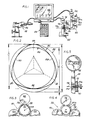
- Fig. 1 is a view of an apparatus in accordance with the invention, suitable for carrying out the method of the invention.
- Fig. 2 is a diagrammatic cross-sectional view of a trilobular body indicating various dimensions and dimensional relationships thereof;
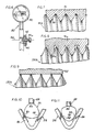
- Fig. 3 is an enlarged, partial cross-sectional view of a roller-type gage instrument of the apparatus of Fig. 1, taken on the line 3-3 of Fig. 1;
- Fig. 4 is an enlarged, partial cross-sectional view of a second roller-type gage instrument forming a part of the apparatus of Fig. 1, taken on the line 4-4 of Fig. 1;
- Figs. 5 and 6 are enlarged partial views, partially in cross-section of the respective roller gage apparatuses of Fig. 1;
- Fig. 7 is an enlarged, partial cross-sectional view through a grooved roller apparatus of a form for engagement with a threaded fastener having a conventional thread form;
- Fig. 8 is a cross-section similar to Fig. 7 showing a modified form of grooved roller formed for engagement with a threaded fastener having a modified thread form;
- Fig. 9 is a cross-sectional view similar to Figs. 7 and 8 but showing engagement of a threaded fastener by the smooth-faced roller of Fig. 4; and
- Figs. 10 and 11 illustrate engagement of a trilobular fastener with an alternate form of gaging instrument illustrated in Fig. 1.
- Referring now to the drawings and initially to Fig. 1, there is shown an apparatus in accordance with the invention which is also suitable for carrying out the method of the invention. The apparatus includes at least one gage apparatus or gage means such as a roller-
type gage 20, which will be more fully described hereinbelow. In the illustrated embodiment, a second similar roller-type gage 22, also to be more fully discussed hereinbelow is also provided. Alternatively, a gage of the type indicated byreference numeral 24 in Fig. 1 might be utilized, although roller-type gages such asgages alternate type gage 24 is of the type referred to as a V-anvil micrometer. - The method of the invention gages the out of round or so-called K dimension of a fastener which may be a threaded fastener or an unthreaded fastener blank, as the term "fastener" is to be understood, when used hereinafter. The fastener may be poly-arcuate or lobular in shape, or round. In the former case, the K dimension may also be referred to as the degree of lobulation. However, the ensuing description is facilitated by reference particularly to a
trilobular body 30, which may be a fastener blank or a trilobular threaded fastener. Atrilobular body 30 is indicated generally in Fig. 2. An unthreaded trilobular blank, which is designated byreference numeral 30a is shown in Figs. 1 and 6, while a completed threaded trilobular fastener designated byreference numeral 30b is shown in Figs. 1 and 5. Thefastener 30b may also be provided with a tapered or conical lead-in surface ortip 35, such as in a thread-forming type of fastener. - The
trilobular body 30 in the example shown in the drawings, is placed in surface-to-surface contact with one or both of thegages inscribing circles trilobular body 30. The orientation of a body 30 (which may be blank 30a or threadedfastener 30b) with respect to thegage 20 is indicated in cross-section and somewhat diagrammatically in Fig. 3. In similar fashion, the engagement of a threadedfastener 30b with thegage 22 is shown in somewhat diagrammatic cross-sectional form in Fig. 4. A somewhat enlarged view of thegages trilobular body 30 generally with the anvil-type micrometer 24 are shown in Figs. 10 and 11, respectively. The ensuing discussion will refer, in additional detail to the gages as illustrated in these respective figures of drawing and to the gaging method of the invention for gaging both threaded and unthreaded fasteners, both of poly-arcuate and round form, as well as similar bodies, to determine out-of-roundness thereof. - Referring to Fig. 1, the apparatus and method of the invention proceed by recording data corresponding to the measurements made by the respective gages and ascertaining a predetermined relationship between the inscribed circle and circumscribed circle from this recorded data. The means for recording and processing the data is indicated at Fig. 1 as a data-
processing unit 26. An additionalCRT type display 28 may also be coupled with the data-processing unit 26 to display data associated with these measurements. We have selected as a data-processing unit 26 a DATAbank Plus System from Brown & Sharpe, Inc., North Kingstown, R.I. We have modified the Databank Plus software, as indicated in the microfiche appendix. Any CRT display may be used, we have selected a Wyse monitor. - Referring now to Fig. 2, we have discovered that useful statistical data for manufacturing control and batch processing can be obtained by determining the difference between the respective pitch cylinder diameters corresponding to the respective inscribed or inscribing circle 34 (E) and circumscribed or circumscribing circle 32 (C) of a poly-arcuate or lobular body. One-half of this difference constitutes the K or out of round dimension of the body. In this regard it will be seen that a trilobular body has been illustrated in diametral cross-section in Fig. 2. This
trilobular body 30 has a geometry as is generally described in U.S. patent to Phipard, No. 3,195,156, for example. That is, the trilobular cross-sectional shape will be seen to have threelobes arcuate sides circumscribing circle 32 or diameter C will be seen to form tangents to the three lobes, while theinscribing circle 34 or diameter E forms a tangent to the arcuate sides. - As mentioned hereinabove, we have found that one-half of the difference between these diametral dimensions, sometimes designated as the K dimension, out of round, or degree of lobulation of the lobular shape, is a significant measurement in determining product acceptability.
- Briefly, when using the anvil-
type micrometer 24, and referring to Figs. 10 and 11, the circumscribing circle is measured as shown in Fig. 10 by placing thelobes body 30 in contact with the respective three relevant surfaces of the micrometer. It will be seen in this regard that the micrometer has a generally V-shapedanvil portion 46 and a selectively advanceable and retractable, preferably flat-endedcylindrical spindle member 48. Similarly, as seen in Fig. 11, the inscribing circle diameter is obtained by placing thearcuate sides anvil 46 and thespindle 48. - While the method and apparatus have been described thus far with reference to a
trilobular body 30, it should be recognized that the apparatus and method herein described is also applicable to measuring unacceptable ovality of out-of-roundness of round-bodied fasteners whether threaded or unthreaded blanks, as well. Often this condition goes undetected using presently available gaging systems. - Referring now in more detail to Figs. 3-9, the method and apparatus for obtaining these measurements with the roller-
type gages type gages such rollers central axes body 30, (be it threadedfastener 30a or blank 30b) is inserted into each gage, its axis is also coincident with thecentral gage axis - The
rollers gage 20 are arranged with smooth surfaces for contacting an outer surface of the body to be measured, which body may be an unthreaded member such as blank 30a or a threaded fastener such asfastener 30b, as well as being either lobular or round in form. These rollers can measure both the circumscribedcircle 32 and the inscribedcircle 34 of an outer surface of the body as the body to be measured is rotated therewithin. In the case of a threaded fastener such asfastener 30b, these measurements will yield a measure of the K, or out of round dimension of the outer diameter or thread crest diameters of the fastener. - In the case of a threaded fastener such as
fastener 30b, an additional gage such asgage 22, which employs groovedrollers circles gage 20 is illustrated with respect toroller 62, for example, in Fig. 9. Accordingly, for a threaded fastener two separate out of round or K dimensions will be determined, one for the outer diameter of the thread and one for the pitch line diameter of the thread. - Accordingly, the
rollers rollers reference numeral 80 in Fig. 7, and an alternative groove form indicated by reference numeral 80a in Fig. 8 are shaped to make contact with the threads of a threaded fastener in such a way as to effect the measurement of the C and E dimensions at the pitch line or pitch diameter of the fastener. Moreover, therespective grooves 80 and 80a are further shaped in complementary form to the pitch or shapes of the threads which they are intended to measure at the pitch line. For example, thegrooves 80 of Fig. 6 are generally tapered in a complementary fashion for entering the threads of thefastener 30b shown therein. - On the other hand,
exemplary fastener 130b of Fig. 8 has a somewhat different thread pitch profile and hence the grooves 80a are somewhat more rectangularly shaped at their inner aspects and convergent at their outer aspects to accommodate this thread-form offastener 130b. The thread form offastener 130b is generally that described in U.S. patent 4,820,098 to Taubert et al, wherein the flank angle of the thread is on the order of 60° and the flank angle of the thread crests extending beyond the nominal diameter of the screw is on the order of 30°. Accordingly, the form of the grooves 80a is varied somewhat to accommodate this sort of thread form. The form of thegrooves 80, 80a may be further varied as appropriate for any desired thread form angle design without departing from the invention. That is, thegrooved rollers - In accordance with the method and apparatus of the invention, suitable direct indicators or indicator means 90, 92 and 94 may also be provided on the
respective gages - The method and apparatus of the invention also contemplate measuring the shape or envelope of a tapered, lead in or thread-forming portion 35 (see Figs. 5 and 6) of a thread forming type of fastener. This is preferably accomplished using the roller-
type gages fastener 30 substantially 360° and obtaining statistical data therefrom for determining the "aggregate" out-of-round dimension of the fastener. - In the case of thread rolling or thread-forming screws, it is estimated that as much as 95% or more of the work or effort in forming internal threads is performed by the lead threads. The lead threads may be considered to be enveloped or circumscribed within a lobular, frustoconical shape with lobes corresponding in number with those of the body threads. The angle of this cone and number of lead threads is governed by the individual product specifications from one fastener to another. However, it will be appreciated that the C and E dimensions will therefore vary from thread to thread, along this tapered lead-in portion. The driving effort in the installation of such a thread-rolling or thread-forming screw is generally indicated by the applied torque measured over the degrees of rotation (expressed in radians) of the screw. As the screw is driven, the rotation is accompanied by a progressive radial outward movement of the lead threads with increasing torque in forming complementary internal mating threads in the workpiece or nut. Consequently, the method and apparatus of the invention may also be used in evaluating the relationship of the K or out-of-round dimension to the rotation of the lead threads of such a thread-forming fastener, to assure the same are formed in such a manner as to obtain the desired driving effort and thread forming action.
- Using the method and apparatus of the invention, the depth of the
grooves 80 would be dictated by product specifications, as mentioned above. However, this could be varied up to .325 P (pitch). As the point threads are captured within the grooved rolls and the screw is rotated, the gage readings will follow the generally undulating pattern of the lobular form with the measured values increasing along a slope generally the same as the slope of the point angle of the lead threads until the body threads of a uniform or constant width or diameter are reached. Accordingly, a measure is obtained of radial penetration of the threads against rotation of the fastener and the gradual formation of complementary internal or mating threads in a workpiece. This path of radial penetration versus rotation can be plotted or recorded in appropriate fashion by the data-processing means 26 and for display upon the display means 28. The taper of the lead-in portion may also be measured against a desired specification for the product by use of the method and apparatus of the invention. - We prefer the use of the roller-type gages over the method using the so-called V-anvil gage as discussed above with reference to Figs. 10 and 11. In using the anvil gage, it is necessary to hold the body to be measured stationary during measurement, and it is necessary to properly and accurately position the body, as shown in Figs. 10 and 11, to obtain the proper dimensional measurements. In practice, this may be done by rotating the body slightly and accepting or recording only the maximum and minimum relative readings as being representative of the respective circumscribed and inscribed circle diameters. It will be appreciated that with a full 360° rotation of the body as contemplated when using the roller type gages 20, 22, slight variations or irregularities of the fastener will also be measured and taken into account in arriving at an aggregate out-of-round or K reading, or data measurement.
- The invention further contemplates developing statistical data from measurements taken on a plurality of bodies or fasteners, which data may be utilized in lot control or processing control applications. The method also contemplates determining from the recorded data points of maximum deviation on the inscribed circle and circumscribed circle diameters of each body or fastener as related to mean measured values thereof.
- It will be further noted that the measurement of the out-of-round or K dimension accomplished by the apparatus and method of the invention also effectively results in a measurement of what is normally called the pitch diameter or effective diameter in the case of a threaded fastener.
- A program listing of modifications to the above-identified Databank Plus software for operating the data processor in accordance with the invention has been submitted herewith as a microfiche appendix.
- While particular embodiments of the invention have been shown and described in detail, it will be obvious to those skilled in the art that changes and modifications of the present invention, in its various aspects, may be made without departing from the invention in its broader aspects, some of which changes and modifications being matters of routine engineering or design, and others being apparent only after study. As such, the scope of the invention should not be limited by the particular embodiment and specific construction described herein but should be defined by the appended claims and equivalents thereof. Accordingly, the aim in the appended claims is to cover all such changes and modifications as fall within the true spirit and scope of the invention.
Claims (26)
- A method for gaging a body comprising: providing gage means (20 or 22) comprising a plurality of rollers (60, 62, 64 or 70, 72, 74) in a spaced circumferential array about a central axis (65 or 75), each of said rollers having an external surface shaped for engaging said body in such a way as to permit measuring predetermined cross-sectional dimensions of said body (30); rotating said body to be gaged in surface-to-surface contact with said rollers; recording information corresponding to movement of at least one of said rollers during said rotating to form recorded data, and ascertaining a predetermined relationship between said predetermined cross-sectional dimensions from said recorded data.
- The method of claim 1 and further including recording a plurality of said predetermined dimensions and the respective said predetermined relationships therebetween for a plurality of bodies and developing therefrom statistical data.
- The method of claim 1 wherein said ascertaining a predetermined relationship comprises determining an out of round dimension of the body.
- A method for gaging threaded fasteners comprising: providing gage means (20 or 22 or 24) for measuring a plurality of cross-sectional dimensions of a threaded fastener (20b); positioning a fastener in surface-to-surface contact with said gage means; recording information corresponding to the dimensions as measured by said gage means during said positioning of said fastener in surface-to-surface contact therewith, to form recorded data, and ascertaining a predetermined relationship between said cross-sectional dimensions from said recorded data.
- The method of claim 4 wherein the step of positioning comprises positioning a holding portion of said fastener in said gage means.
- The method of claim 4 wherein the step of positioning comprises positioning a lead-in portion of said fastener in said gage means.
- The method of claim 6 wherein the step of positioning includes axially advancing said lead-in portion relative to said gage means and said method further including developing data representative of the shape of said lead-in portion.
- The method of claim 7 wherein the step of developing data includes determining the envelope shape of said lead-in portion.
- The method of claim 8 and further including recording a plurality of said envelope shapes which have been determined for a plurality of fasteners and developing statistical data therefrom.
- The method of claim 4 and further including determining from said recorded data the out-of-round of a poly-arcuate fastener.
- The method of claim 4 and further including determining from said recorded data the out of round of a round body fastener.
- The method of claim 4 and further including determining from said recorded data the points of maximum deviation on the inscribed circle and circumscribed circle diameters of said fastener, as related to mean measured values thereof.
- Apparatus for gaging threaded fasteners comprising: gage means (20 or 22) comprising a plurality of roller means (60, 62, 64 or 70, 72, 74) in a spaced, circumferential array about a central axis (65 or 75), each of said roller means having an external surface shaped for engaging said fastener in such a way as to permit measuring predetermined cross-sectional dimensions of said threaded fastener; recording means (26) responsive to movement of at least one of said roller means during rotation of a fastener in surface-to-surface contact with said roller means for recording predetermined corresponding recorded data, and data processing means (26) for ascertaining a predetermined relationship between said predetermined cross-sectional dimensions from said recorded data.
- The apparatus of claim 13 wherein said external roller surfaces are smooth, continuous surfaces for measuring dimensions at a thread crest.
- The apparatus of claim 13 wherein said external roller surfaces are circumferentially formed with grooves shaped for engagement with the thread of the fastener to be gaged for measuring dimensions at the pitch line of the thread.
- The apparatus of claim 13 wherein said data processing means (26) further include means for processing a plurality of said dimensions which have been ascertained for a plurality of fasteners and developing statistical data therefrom.
- The apparatus of claim 13 and further including observable indicator means (90, 92) for direct reading of measured dimensions of each fastener.
- The apparatus of claim 13 wherein said data processing means (26) determines the out of round dimension of the fastener.
- The apparatus of claim 15 wherein said grooves of said rollers have a radial depth of no greater than the order of .325 P.
- The apparatus of claim 15 wherein said grooves are formed for gaging said pitch line dimensions of a fastener having a thread with a first flank angle of substantially on the order of 60° and a second flank angle of thread crests extending beyond the nominal diameter of the fastener of substantially on the order of 30°.
- Apparatus for gaging a body comprising; gage means (20 or 22 or 24) of complementary form for surface-to-surface contact with a body to be gaged in such a manner as to measure a plurality of cross-sectional dimensions of said body; recording means (26) responsive to said gage means for recording the dimensions of a body obtained thereby, and data processing means (26) for ascertaining predetermined relationships between the cross-sectional dimensions of a body from the recorded data.
- The apparatus of claim 21 wherein said data processing means determines an out of round dimension of said body.
- A method for gaging threaded lobular bodies comprising: providing gage means (20 o4 22 or 24) for measuring a plurality of cross-sectional dimensions of a lobular body; positioning a lobular body in surface-to-surface contact with said gage means; recording information corresponding to the dimensions as measured by said gage means during said positioning of said lobular body in surface-to-surface contact therewith, to form recorded data, and ascertaining a predetermined relationship between said cross-sectional dimensions from said recorded data.
- The method of claim 23 wherein said determining of a predetermined relationship comprises determining an out of round dimension of the lobular body.
- Apparatus for gaging threaded fasteners comprising gage means (20 or 22 or 24) of complementary form for surface-to-surface contact with a fastener to be gaged in such a manner as to measure a plurality of cross-sectional dimensions of said fastener; recording means (26) responsive to said gage means for recording the dimensions of a fastener obtained thereby, and data processing means (26) for ascertaining predetermined relationships between the cross-sectional dimensions of a fastener from the recorded data.
- The apparatus of claim 25 wherein said data processing means (26) determines an out of round dimension of said fastener.
Applications Claiming Priority (4)
| Application Number | Priority Date | Filing Date | Title |
|---|---|---|---|
| US49461290A | 1990-03-16 | 1990-03-16 | |
| US494612 | 1990-03-16 | ||
| US07/550,701 US5168458A (en) | 1990-03-16 | 1990-07-10 | Method and apparatus for gaging the degree of lobulation of bodies such as threaded fasteners |
| US550701 | 1990-07-10 |
Publications (3)
| Publication Number | Publication Date |
|---|---|
| EP0447048A2 true EP0447048A2 (en) | 1991-09-18 |
| EP0447048A3 EP0447048A3 (en) | 1992-02-12 |
| EP0447048B1 EP0447048B1 (en) | 1995-04-19 |
Family
ID=27051468
Family Applications (1)
| Application Number | Title | Priority Date | Filing Date |
|---|---|---|---|
| EP91301432A Expired - Lifetime EP0447048B1 (en) | 1990-03-16 | 1991-02-22 | Method and apparatus for gaging bodies such as threaded fasteners and blanks |
Country Status (7)
| Country | Link |
|---|---|
| US (1) | US5168458A (en) |
| EP (1) | EP0447048B1 (en) |
| JP (1) | JP3046636B2 (en) |
| BR (1) | BR9101034A (en) |
| CA (1) | CA2036439A1 (en) |
| DE (1) | DE69108966T2 (en) |
| ES (1) | ES2071209T3 (en) |
Families Citing this family (37)
| Publication number | Priority date | Publication date | Assignee | Title |
|---|---|---|---|---|
| US6145207A (en) * | 1998-03-23 | 2000-11-14 | Brunson Instrument Company | Thread pitch diameter measuring system |
| US6286227B1 (en) * | 1998-08-03 | 2001-09-11 | General Electric Company | Micrometer system and process of use therefor |
| US7752266B2 (en) | 2001-10-11 | 2010-07-06 | Ebay Inc. | System and method to facilitate translation of communications between entities over a network |
| JP4677603B2 (en) * | 2005-08-26 | 2011-04-27 | 株式会社ユタカ | Screw shaft diameter measuring device |
| US8639782B2 (en) | 2006-08-23 | 2014-01-28 | Ebay, Inc. | Method and system for sharing metadata between interfaces |
| US7684054B2 (en) | 2006-08-25 | 2010-03-23 | Gii Acquisition, Llc | Profile inspection system for threaded and axial components |
| US8041150B2 (en) * | 2006-11-29 | 2011-10-18 | The United States Of America As Represented By The Secretary Of Agriculture | Method and apparatus for determining the surface area of a threaded fastener |
| US7738088B2 (en) * | 2007-10-23 | 2010-06-15 | Gii Acquisition, Llc | Optical method and system for generating calibration data for use in calibrating a part inspection system |
| US7633634B2 (en) * | 2007-10-23 | 2009-12-15 | Gii Acquisition, Llc | Optical modules and method of precisely assembling same |
| US7777900B2 (en) * | 2007-10-23 | 2010-08-17 | Gii Acquisition, Llc | Method and system for optically inspecting parts |
| US7755754B2 (en) * | 2007-10-23 | 2010-07-13 | Gii Acquisition, Llc | Calibration device for use in an optical part measuring system |
| US8550444B2 (en) * | 2007-10-23 | 2013-10-08 | Gii Acquisition, Llc | Method and system for centering and aligning manufactured parts of various sizes at an optical measurement station |
| US7812970B2 (en) * | 2007-10-23 | 2010-10-12 | Gii Acquisition, Llc | Method and system for inspecting parts utilizing triangulation |
| US7633046B2 (en) * | 2007-10-23 | 2009-12-15 | Gii Acquisition Llc | Method for estimating thread parameters of a part |
| US7738121B2 (en) * | 2007-10-23 | 2010-06-15 | Gii Acquisition, Llc | Method and inspection head apparatus for optically measuring geometric dimensions of a part |
| US7920278B2 (en) * | 2007-10-23 | 2011-04-05 | Gii Acquisition, Llc | Non-contact method and system for inspecting parts |
| US8132802B2 (en) * | 2007-10-23 | 2012-03-13 | Gii Acquisition, Llc | Apparatus for quickly retaining and releasing parts to be optically measured |
| US8237935B2 (en) * | 2007-10-23 | 2012-08-07 | Gii Acquisition, Llc | Method and system for automatically inspecting parts and for automatically generating calibration data for use in inspecting parts |
| US7796278B2 (en) * | 2008-09-19 | 2010-09-14 | Gii Acquisition, Llc | Method for precisely measuring position of a part to be inspected at a part inspection station |
| US8004694B2 (en) * | 2009-03-27 | 2011-08-23 | Gll Acquistion LLC | System for indirectly measuring a geometric dimension related to an opening in an apertured exterior surface of a part based on direct measurements of the part when fixtured at a measurement station |
| SG181170A1 (en) * | 2010-09-15 | 2012-07-30 | Wu Naien | Apparatus for inspecting rotary parts and the method of the inspection |
| US8390826B2 (en) | 2011-04-20 | 2013-03-05 | Gii Acquisition, Llc | Method and system for optically inspecting parts |
| US9575013B2 (en) | 2011-05-17 | 2017-02-21 | Gii Acquisition, Llc | Non-contact method and system for inspecting a manufactured part at an inspection station having a measurement axis |
| US8570504B2 (en) | 2011-05-17 | 2013-10-29 | Gii Acquisition, Llc | Method and system for optically inspecting parts |
| US9372160B2 (en) | 2011-05-17 | 2016-06-21 | Gii Acquisition, Llc | Method and system for optically inspecting the ends of a manufactured part at a single inspection station having a measurement axis |
| US9047657B2 (en) | 2011-05-17 | 2015-06-02 | Gii Acquisition, Lcc | Method and system for optically inspecting outer peripheral surfaces of parts |
| US10088431B2 (en) | 2011-05-17 | 2018-10-02 | Gii Acquisition, Llc | Method and system for optically inspecting headed manufactured parts |
| US9697596B2 (en) | 2011-05-17 | 2017-07-04 | Gii Acquisition, Llc | Method and system for optically inspecting parts |
| US10094785B2 (en) | 2011-05-17 | 2018-10-09 | Gii Acquisition, Llc | Method and system for optically inspecting headed manufactured parts |
| US9228957B2 (en) | 2013-05-24 | 2016-01-05 | Gii Acquisition, Llc | High speed method and system for inspecting a stream of parts |
| US9486840B2 (en) | 2013-05-24 | 2016-11-08 | Gii Acquisition, Llc | High-speed, triangulation-based, 3-D method and system for inspecting manufactured parts and sorting the inspected parts |
| US8993914B2 (en) | 2012-12-14 | 2015-03-31 | Gii Acquisition, Llc | High-speed, high-resolution, triangulation-based, 3-D method and system for inspecting manufactured parts and sorting the inspected parts |
| US10207297B2 (en) | 2013-05-24 | 2019-02-19 | GII Inspection, LLC | Method and system for inspecting a manufactured part at an inspection station |
| US9539619B2 (en) | 2013-05-24 | 2017-01-10 | Gii Acquisition, Llc | High speed method and system for inspecting a stream of parts at a pair of inspection stations |
| US9377297B2 (en) | 2013-08-21 | 2016-06-28 | Gii Acquisition, Llc | High-resolution imaging and processing method and system for increasing the range of a geometric dimension of a part that can be determined |
| US9372077B2 (en) | 2013-08-21 | 2016-06-21 | Gii Acquistion, Llc | High-resolution imaging and processing method and system for determining a geometric dimension of a part |
| US10300510B2 (en) | 2014-08-01 | 2019-05-28 | General Inspection Llc | High speed method and system for inspecting a stream of parts |
Citations (4)
| Publication number | Priority date | Publication date | Assignee | Title |
|---|---|---|---|---|
| US3879854A (en) * | 1974-07-01 | 1975-04-29 | Johnson Co Gage | Screw thread comparator gaging device having ti-point and segmental gaging means using a single indicator |
| US4106206A (en) * | 1977-04-25 | 1978-08-15 | The United States Of America As Represented By The Secretary Of The Navy | Positively expandable and retractable thread measuring gage |
| GB2187289A (en) * | 1986-03-01 | 1987-09-03 | Skf Gmbh | Determining charactistic of a curved surface |
| EP0287502A1 (en) * | 1987-03-17 | 1988-10-19 | Horst Günter Rissmann | Thread testing and measuring device |
Family Cites Families (10)
| Publication number | Priority date | Publication date | Assignee | Title |
|---|---|---|---|---|
| US4064633A (en) * | 1976-03-10 | 1977-12-27 | Wertepny Alexander W | Gauging instrument |
| US4490800A (en) * | 1981-12-14 | 1984-12-25 | Powers Manufacturing, Inc. | Dual head gauger apparatus with automatic adjustment for pressure variation |
| IL69732A0 (en) * | 1982-09-20 | 1983-12-30 | Schweiz Ges Werkzeugmasch | Method and apparatus for determining the precision of a numerically controlled machine tool |
| US4736313A (en) * | 1984-02-24 | 1988-04-05 | Mitutoyo Mfg. Co., Ltd. | Digital indication type length measuring system |
| IT1179343B (en) * | 1984-05-28 | 1987-09-16 | Finike Italiana Marposs | APPARATUS TO CONTROL THE ROUNDNESS OF PIECES IN ROTATION |
| DE3511564A1 (en) * | 1985-03-29 | 1986-10-02 | Hommelwerke GmbH, 7730 Villingen-Schwenningen | DEVICE FOR MEASURING THE CIRCULAR DIFFERENCE OF ECCENTRIC BEARING AREAS, IN PARTICULAR CONNECTING BEARINGS |
| FR2593100B1 (en) * | 1986-01-17 | 1988-03-25 | Snecma | DEVICE FOR POSITIONING A CIRCULAR PART. |
| US4930096A (en) * | 1987-01-22 | 1990-05-29 | Man Design Co., Ltd. | Data-transmitting apparatus having connecting plug |
| GB8728016D0 (en) * | 1987-11-30 | 1988-01-06 | Grosvenor R I | Methods and apparatus for measuring transverse dimensions of workpieces |
| JPH02296127A (en) * | 1989-05-10 | 1990-12-06 | Bridgestone Corp | Method for inspecting defect of pneumatic tire |
-
1990
- 1990-07-10 US US07/550,701 patent/US5168458A/en not_active Expired - Lifetime
-
1991
- 1991-02-15 CA CA002036439A patent/CA2036439A1/en not_active Abandoned
- 1991-02-22 ES ES91301432T patent/ES2071209T3/en not_active Expired - Lifetime
- 1991-02-22 DE DE69108966T patent/DE69108966T2/en not_active Expired - Fee Related
- 1991-02-22 EP EP91301432A patent/EP0447048B1/en not_active Expired - Lifetime
- 1991-03-12 JP JP3074036A patent/JP3046636B2/en not_active Expired - Fee Related
- 1991-03-15 BR BR919101034A patent/BR9101034A/en not_active IP Right Cessation
Patent Citations (4)
| Publication number | Priority date | Publication date | Assignee | Title |
|---|---|---|---|---|
| US3879854A (en) * | 1974-07-01 | 1975-04-29 | Johnson Co Gage | Screw thread comparator gaging device having ti-point and segmental gaging means using a single indicator |
| US4106206A (en) * | 1977-04-25 | 1978-08-15 | The United States Of America As Represented By The Secretary Of The Navy | Positively expandable and retractable thread measuring gage |
| GB2187289A (en) * | 1986-03-01 | 1987-09-03 | Skf Gmbh | Determining charactistic of a curved surface |
| EP0287502A1 (en) * | 1987-03-17 | 1988-10-19 | Horst Günter Rissmann | Thread testing and measuring device |
Also Published As
| Publication number | Publication date |
|---|---|
| ES2071209T3 (en) | 1995-06-16 |
| JPH06186026A (en) | 1994-07-08 |
| DE69108966D1 (en) | 1995-05-24 |
| EP0447048A3 (en) | 1992-02-12 |
| DE69108966T2 (en) | 1995-08-24 |
| CA2036439A1 (en) | 1991-09-17 |
| JP3046636B2 (en) | 2000-05-29 |
| BR9101034A (en) | 1991-11-05 |
| EP0447048B1 (en) | 1995-04-19 |
| US5168458A (en) | 1992-12-01 |
Similar Documents
| Publication | Publication Date | Title |
|---|---|---|
| EP0447048B1 (en) | Method and apparatus for gaging bodies such as threaded fasteners and blanks | |
| US5170306A (en) | Method and apparatus for gaging the geometry of point threads and other special threads | |
| EP1835256B1 (en) | Screw measuring method, screw measuring probe, and screw measuring apparatus using the screw measuring probe | |
| CN110631534B (en) | Method for detecting pitch diameter and pitch of taper thread of oil sleeve joint | |
| CN106052576A (en) | screw-thread measuring device and method | |
| US6598305B1 (en) | Spline gage system and method | |
| US20030088991A1 (en) | Single-side measuring devices and methods | |
| US6612042B1 (en) | Thread gage system and method | |
| AU630540B2 (en) | Method and apparatus for gaging bodies such as threaded fasteners and blanks | |
| JPH02649B2 (en) | ||
| US4417402A (en) | Gauging of thread diameters | |
| US5343624A (en) | Measurement tool | |
| CN106767315B (en) | A kind of cubing of center distance between holes | |
| JPH0961102A (en) | Screw plug gauge | |
| CN206095112U (en) | Circular arc screw thread structure detection device | |
| US2680301A (en) | Pipe thread gauge | |
| US4219938A (en) | Method and means for gauging of threads | |
| US5377417A (en) | Thread pitch cylinder gage | |
| EP3088841B1 (en) | Method and device for evaluating surface characteristics based on the angle-resolved stray light measuring method with automatic determination of the position of the workpiece | |
| Ghosh et al. | Understanding Mathematical Definitions of Circularity/Roundness in ASME GD&T Y14. 5 As Related to Part Functionality | |
| RU2166729C1 (en) | Method of check of shape and diameters of inner sections of large- sized cylindrical parts | |
| CN105627884A (en) | Nut detection tool and method | |
| JPS59208414A (en) | Method and apparatus for measuring accuracy of gear | |
| JPH02648B2 (en) | ||
| CN219869417U (en) | Quick bolt detection ruler |
Legal Events
| Date | Code | Title | Description |
|---|---|---|---|
| PUAI | Public reference made under article 153(3) epc to a published international application that has entered the european phase |
Free format text: ORIGINAL CODE: 0009012 |
|
| AK | Designated contracting states |
Kind code of ref document: A2 Designated state(s): CH DE ES FR GB LI SE |
|
| PUAL | Search report despatched |
Free format text: ORIGINAL CODE: 0009013 |
|
| AK | Designated contracting states |
Kind code of ref document: A3 Designated state(s): CH DE ES FR GB LI SE |
|
| 17P | Request for examination filed |
Effective date: 19920731 |
|
| 17Q | First examination report despatched |
Effective date: 19931013 |
|
| GRAA | (expected) grant |
Free format text: ORIGINAL CODE: 0009210 |
|
| AK | Designated contracting states |
Kind code of ref document: B1 Designated state(s): CH DE ES FR GB LI SE |
|
| REF | Corresponds to: |
Ref document number: 69108966 Country of ref document: DE Date of ref document: 19950524 |
|
| ET | Fr: translation filed | ||
| REG | Reference to a national code |
Ref country code: ES Ref legal event code: FG2A Ref document number: 2071209 Country of ref document: ES Kind code of ref document: T3 |
|
| PLBE | No opposition filed within time limit |
Free format text: ORIGINAL CODE: 0009261 |
|
| STAA | Information on the status of an ep patent application or granted ep patent |
Free format text: STATUS: NO OPPOSITION FILED WITHIN TIME LIMIT |
|
| 26N | No opposition filed | ||
| REG | Reference to a national code |
Ref country code: GB Ref legal event code: IF02 |
|
| PGFP | Annual fee paid to national office [announced via postgrant information from national office to epo] |
Ref country code: ES Payment date: 20080226 Year of fee payment: 18 Ref country code: CH Payment date: 20080228 Year of fee payment: 18 |
|
| PGFP | Annual fee paid to national office [announced via postgrant information from national office to epo] |
Ref country code: GB Payment date: 20080227 Year of fee payment: 18 Ref country code: SE Payment date: 20080227 Year of fee payment: 18 |
|
| PGFP | Annual fee paid to national office [announced via postgrant information from national office to epo] |
Ref country code: FR Payment date: 20080218 Year of fee payment: 18 Ref country code: DE Payment date: 20080331 Year of fee payment: 18 |
|
| REG | Reference to a national code |
Ref country code: CH Ref legal event code: PL |
|
| EUG | Se: european patent has lapsed | ||
| GBPC | Gb: european patent ceased through non-payment of renewal fee |
Effective date: 20090222 |
|
| PG25 | Lapsed in a contracting state [announced via postgrant information from national office to epo] |
Ref country code: CH Free format text: LAPSE BECAUSE OF NON-PAYMENT OF DUE FEES Effective date: 20090228 Ref country code: LI Free format text: LAPSE BECAUSE OF NON-PAYMENT OF DUE FEES Effective date: 20090228 |
|
| REG | Reference to a national code |
Ref country code: FR Ref legal event code: ST Effective date: 20091030 |
|
| PG25 | Lapsed in a contracting state [announced via postgrant information from national office to epo] |
Ref country code: DE Free format text: LAPSE BECAUSE OF NON-PAYMENT OF DUE FEES Effective date: 20090901 |
|
| REG | Reference to a national code |
Ref country code: ES Ref legal event code: FD2A Effective date: 20090223 |
|
| PG25 | Lapsed in a contracting state [announced via postgrant information from national office to epo] |
Ref country code: GB Free format text: LAPSE BECAUSE OF NON-PAYMENT OF DUE FEES Effective date: 20090222 Ref country code: FR Free format text: LAPSE BECAUSE OF NON-PAYMENT OF DUE FEES Effective date: 20090302 |
|
| PG25 | Lapsed in a contracting state [announced via postgrant information from national office to epo] |
Ref country code: ES Free format text: LAPSE BECAUSE OF NON-PAYMENT OF DUE FEES Effective date: 20090223 |
|
| PG25 | Lapsed in a contracting state [announced via postgrant information from national office to epo] |
Ref country code: SE Free format text: LAPSE BECAUSE OF NON-PAYMENT OF DUE FEES Effective date: 20090223 |