EP0446736B1 - Machine de cerclage pour palettes - Google Patents
Machine de cerclage pour palettes Download PDFInfo
- Publication number
- EP0446736B1 EP0446736B1 EP91103169A EP91103169A EP0446736B1 EP 0446736 B1 EP0446736 B1 EP 0446736B1 EP 91103169 A EP91103169 A EP 91103169A EP 91103169 A EP91103169 A EP 91103169A EP 0446736 B1 EP0446736 B1 EP 0446736B1
- Authority
- EP
- European Patent Office
- Prior art keywords
- bayonet
- hoop
- aggregate
- casing
- pallet
- Prior art date
- Legal status (The legal status is an assumption and is not a legal conclusion. Google has not performed a legal analysis and makes no representation as to the accuracy of the status listed.)
- Expired - Lifetime
Links
- 229920001169 thermoplastic Polymers 0.000 claims description 2
- 239000004416 thermosoftening plastic Substances 0.000 claims description 2
- 230000000295 complement effect Effects 0.000 claims 1
- 238000007789 sealing Methods 0.000 claims 1
- 239000003795 chemical substances by application Substances 0.000 description 2
- 229910000831 Steel Inorganic materials 0.000 description 1
- 230000000712 assembly Effects 0.000 description 1
- 238000000429 assembly Methods 0.000 description 1
- 238000010276 construction Methods 0.000 description 1
- 230000000284 resting effect Effects 0.000 description 1
- 238000000926 separation method Methods 0.000 description 1
- 239000010959 steel Substances 0.000 description 1
- 230000001502 supplementing effect Effects 0.000 description 1
- 238000004804 winding Methods 0.000 description 1
Images

Classifications
-
- B—PERFORMING OPERATIONS; TRANSPORTING
- B65—CONVEYING; PACKING; STORING; HANDLING THIN OR FILAMENTARY MATERIAL
- B65B—MACHINES, APPARATUS OR DEVICES FOR, OR METHODS OF, PACKAGING ARTICLES OR MATERIALS; UNPACKING
- B65B13/00—Bundling articles
- B65B13/02—Applying and securing binding material around articles or groups of articles, e.g. using strings, wires, strips, bands or tapes
- B65B13/04—Applying and securing binding material around articles or groups of articles, e.g. using strings, wires, strips, bands or tapes with means for guiding the binding material around the articles prior to severing from supply
- B65B13/06—Stationary ducts or channels
Definitions
- the invention relates to a machine for strapping palletized packaged goods including the pallet with a strapping agent, in particular a thermoplastic band, consisting essentially of a portal, a bayonet supplementing this to a circumferential band guide channel for the strapping agent and an assembly for the preparation, conveying and the closure of the strapping means, both the bayonet and the unit are each equipped with a drive motor and a linear guide for their essentially horizontal relative movement to the packaged goods and portal.
- a strapping agent in particular a thermoplastic band, consisting essentially of a portal, a bayonet supplementing this to a circumferential band guide channel for the strapping agent and an assembly for the preparation, conveying and the closure of the strapping means
- both the bayonet and the unit are each equipped with a drive motor and a linear guide for their essentially horizontal relative movement to the packaged goods and portal.
- the linear guides are realized by means of ball screws. Electric motors each drive a threaded spindle along which a ball screw nut mounted on it is adjusted, to which the movable machine parts are in turn attached.
- the bayonet and / or unit is driven by chain drives controlled by end positions or pneumatic cable cylinders.
- the invention is therefore based on the object of making available a machine which is outlined in the preamble of claim 1 and which is capable of fulfilling the safety requirements in a considerably simplified manner and which can be used in the technically inexpensive linear guides.
- the invention solves this problem primarily and essentially by using rotating field magnets as drive motors for the bayonet and the unit.
- Three-phase magnets are three-phase motors with squirrel-cage rotors, the stators of which are 'overwound', i.e. are provided with a significantly larger number of turns than usual. They are designed electrically so that they can be used at rated voltage with a braked shaft in continuous and intermittent operation with unlimited duty cycle and develop their greatest torque (standstill torque). In principle, you could compare a rotating field magnet with an electric spring with infinite spring travel.
- the invention utilizes these properties of rotating field magnets, which were previously used, for example, to drive church bells or for the winding devices on drums of trailing cables for cranes, to an astonishingly advantageous extent to control the linear movements of the bayonet and / or assembly.
- a rotating field magnet as a direct drive motor for the bayonet and / or unit is considerably simpler and therefore less expensive than, in particular, a ball screw drive or a pneumatic cable cylinder, which besides the electrical connection, which is in any case necessary for the machine, also requires a compressed air supply.
- the linear drive can consequently be designed in a simplest embodiment, which is characterized approximately in that a drive pinion is arranged on the shaft of the rotating field magnet, which meshes with a rack attached to the bayonet or to the unit. It is of further advantage, in particular for reasons of constructive simplification, if the toothed rack is connected to carriages guided on a carrier rail by means of rollers.
- a pallet strapping machine designated overall by 10, includes a portal 11 with posts 12 and 13 and a bar 14, the actual machine unit 15 and a bayonet 16.
- the palletized packaged goods 17/18 are first moved into the portal by means of a transport device indicated by 20, such as roller conveyors. Then the bayonet 16, which is waiting in the rest position on the right in FIG. 1, passes under the pallet 17 and docks at 21 on the post 12. In the usual way, the assembly now shoots the strapping means in the direction of circulation 22 through the strapping channel 19 until the front end of the strapping means is inserted into a closure head 23 of the assembly 15 and is held there. Now the unit 15 moves against that Packaged goods 18 in the position 15 'shown in dashed lines, and the strapping means is then withdrawn against its weft direction, thus pulled out of the strapping channel and finally tightened around the packaged goods. The overlapping strapping sections are ultimately firmly connected to one another in the closure head 23, that is to say generally thermally welded.
- the drive 24 for the bayonet 16 and the drive 25 for the assembly 15 are new and essential to the invention, also in connection with their linear guides 31 and 38.
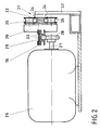
- a rotating field magnet 26 serves as the drive motor for the bayonet 16.
- a pinion 28 is rotatably mounted on its shaft 27 (FIG. 2) and meshes with a toothed rack 29 fastened under the bayonet 16. With 30 the strapping channel in the bayonet 16 is designated, which is mounted on a very simple linear guide 31.
- the linear guide 31 comprises a rail 33 carried by two supports 32 standing on the floor with rail heads 34 made of round steel bars, on which rollers 35 rotatably mounted on carriages 36 run.
- the bayonet 16 is in turn attached to the carriage.
- the pinion 28 drives the bayonet mounted on the linear guide described and, depending on the direction of rotation, either pushes it forward or pulls it back.
- a very similar drive is provided for the assembly 15, whose rotating field magnet is designated 37 and its linear guide is designated 38 (FIG. 1).
- the shaft of the rotating field magnet 37 meshes with a rack secured under the assembly 15.
- the linear guide 38 is attached to the top of the unit 15. Thereby, i.e. due to the spatial separation of drive and guidance, a very stable position of the assembly 15 is achieved.
- the guide rail 39 is connected to the unit 15 in a uniform movement, while the rollers 40 are mounted on a bracket 41 held in a fixed position.
Landscapes
- Engineering & Computer Science (AREA)
- Mechanical Engineering (AREA)
- Basic Packing Technique (AREA)
Claims (4)
- Machine à fardeler un produit à emballer, palettisé, y compris la palette, avec un produit de fardelage, en particulier une bande termoplastique, composée essentiellement d'un portique, d'une baïonnette complétant le portique pour constituer un canal de guidage de bande faisant le pourtour, pour le produit de fardelage, et d'un groupe pour la mise à disposition, le transport et la fermeture du produit de fardelage, où aussi bien la baïonnette qu'également le groupe sont chacun équipés d'un moteur d'entraînement et d'un guidage linéaire pour leur déplacement rotatif sensiblement horizontal par rapport au produit à emballer et au portique, caractérisé par l'utilisation d'un aimant à champ rotatif (26;37) comme moteur d'entraînement pour la baïonnette (16) et/ou le groupe (15).
- Fardeleuse de palettes selon la revendication 1, caractérisée en ce que, sur l'arbre (27) de l'aimant à champ rotatif (26), respectivement (37), est disposé un pignon d'entraînement (28), qui engrène avec une crémaillère (29) fixée sur la baïonnette (16), respectivement sur le groupe (15).
- Fardeleuse à palette selon la revendication 2, caractérisée en ce que la crémaillère est reliée à un chariot (36) guidé sur un rail-support (33) au moyen de galets (35).
- Fardeuleuse à palette selon la revendication 2, caractérisée en ce que l'aimant à champ rotatif (37) destiné à l'entraînement du groupe (25), d'une part, et son guidage linéaire (38), d'autre part, sont disposés sur des côtés opposés du groupe (15).
Applications Claiming Priority (2)
| Application Number | Priority Date | Filing Date | Title |
|---|---|---|---|
| DE4007931A DE4007931A1 (de) | 1990-03-13 | 1990-03-13 | Paletten-umreifungsmaschine |
| DE4007931 | 1990-03-13 |
Publications (2)
| Publication Number | Publication Date |
|---|---|
| EP0446736A1 EP0446736A1 (fr) | 1991-09-18 |
| EP0446736B1 true EP0446736B1 (fr) | 1995-02-01 |
Family
ID=6402065
Family Applications (1)
| Application Number | Title | Priority Date | Filing Date |
|---|---|---|---|
| EP91103169A Expired - Lifetime EP0446736B1 (fr) | 1990-03-13 | 1991-03-02 | Machine de cerclage pour palettes |
Country Status (2)
| Country | Link |
|---|---|
| EP (1) | EP0446736B1 (fr) |
| DE (2) | DE4007931A1 (fr) |
Families Citing this family (7)
| Publication number | Priority date | Publication date | Assignee | Title |
|---|---|---|---|---|
| US5355786A (en) * | 1993-09-21 | 1994-10-18 | Signode Corporation | Strap guide for guiding strap through aligned openings in pallet stringers |
| EP2729378B1 (fr) * | 2011-07-04 | 2015-08-12 | Ecolean AB | Unite de transport et procede pour sa fabrication |
| CN103086002B (zh) * | 2013-02-22 | 2014-12-10 | 杭州永创智能设备股份有限公司 | 一种打包机的机芯 |
| AT514165B1 (de) * | 2013-04-11 | 2015-09-15 | Klein Thomas | Verfahren zur Umreifung von palettierten Waren |
| DE102019118307B4 (de) * | 2019-04-24 | 2025-10-09 | Mosca Gmbh | Verfahren und Vorrichtung zur Umreifung von Paletten |
| CN110342009B (zh) * | 2019-08-16 | 2020-09-11 | 南京斯杩克机器人技术有限公司 | 一种起爆具装箱系统用自动调整捆包机及其自动调整捆包方法 |
| CN111907766A (zh) * | 2020-08-04 | 2020-11-10 | 池州市新辰包装科技有限公司 | 一种单机头双带槽垂直打捆系统 |
Family Cites Families (3)
| Publication number | Priority date | Publication date | Assignee | Title |
|---|---|---|---|---|
| US3899963A (en) * | 1973-12-11 | 1975-08-19 | Signode Corp | Articulated strap chute and guide means therefor |
| US3949662A (en) * | 1975-04-29 | 1976-04-13 | Fmc Corporation | Pallet strapper with projectable lance |
| DE3507091A1 (de) * | 1985-02-28 | 1986-08-28 | Kraftwerk Union AG, 4330 Mülheim | Armatur zum absperren einer stroemung |
-
1990
- 1990-03-13 DE DE4007931A patent/DE4007931A1/de not_active Withdrawn
-
1991
- 1991-03-02 DE DE59104449T patent/DE59104449D1/de not_active Expired - Lifetime
- 1991-03-02 EP EP91103169A patent/EP0446736B1/fr not_active Expired - Lifetime
Also Published As
| Publication number | Publication date |
|---|---|
| DE4007931A1 (de) | 1991-09-19 |
| DE59104449D1 (de) | 1995-03-16 |
| EP0446736A1 (fr) | 1991-09-18 |
Similar Documents
| Publication | Publication Date | Title |
|---|---|---|
| EP1132321B1 (fr) | Transporteur à rouleaux | |
| EP2616379B2 (fr) | Système collecteur de courant, système de grue et procédé permettant de faire avancer un chariot collecteur de courant sur un rail conducteur | |
| DE69208828T2 (de) | Vorrichtung zum Umwickeln von ringförmigen Gegenständen | |
| EP1446315B1 (fr) | Dispositif de divertissement populaire comportant des moyens de freinage a courants de foucault debrayables | |
| EP0000877A1 (fr) | Manipulateur pour positionner des pièces ou d'autres charges | |
| DE1580909A1 (de) | Transportanlage | |
| DE4317998C2 (de) | Spritzgießeinheit für eine Kunststoff-Spritzgießmaschine | |
| DE2208514A1 (de) | Linearmotor mit Wagen | |
| EP0069239B1 (fr) | Dispositif d'entraînement pour le déplacement de demi-produits oblongs | |
| EP0446736B1 (fr) | Machine de cerclage pour palettes | |
| DE2823327A1 (de) | Vorrichtung zum aufwickeln oder abwickeln von materialbahnen fuer bandfoermiges material behandelnde maschinen | |
| DE69603349T2 (de) | Einrichtung zur Handhabung von Wickelrollen | |
| DE19539752C2 (de) | Holmlose Zwei-Platten-Spritzgießmaschine | |
| DE2635437A1 (de) | Drahtziehmaschine | |
| EP0481323B1 (fr) | Procédé pour alimenter une machine de production avec un centrage de précision et dispositif à cet effet | |
| DE4204545C2 (de) | Greifer für einen Linearantrieb | |
| WO2006114128A1 (fr) | Procede et dispositif pour enrouler un produit a enrouler de forme allongee | |
| DE3225595A1 (de) | Transportbahn | |
| EP0289784A1 (fr) | Machine d'enveloppement à feuille | |
| DE1774717A1 (de) | Schleppkabelanlage | |
| DE2915174A1 (de) | Sortiermaschine fuer werkstuecke | |
| DE2832991A1 (de) | Kettenaufzug fuer aneinandergekuppelte fahrzeuggruppen von belustigungsvorrichtungen | |
| DE19612563B4 (de) | Vorrichtung zum Verschieben von zu verpackenden Gegenständen | |
| DE1186300B (de) | Abwickelhaspel fuer Stranggut, insbesondere fuer Bandbunde | |
| DE102004042595A1 (de) | Bandspeicher |
Legal Events
| Date | Code | Title | Description |
|---|---|---|---|
| PUAI | Public reference made under article 153(3) epc to a published international application that has entered the european phase |
Free format text: ORIGINAL CODE: 0009012 |
|
| AK | Designated contracting states |
Kind code of ref document: A1 Designated state(s): CH DE FR GB IT LI |
|
| 17P | Request for examination filed |
Effective date: 19911030 |
|
| 17Q | First examination report despatched |
Effective date: 19940722 |
|
| ITF | It: translation for a ep patent filed | ||
| GRAA | (expected) grant |
Free format text: ORIGINAL CODE: 0009210 |
|
| AK | Designated contracting states |
Kind code of ref document: B1 Designated state(s): CH DE FR GB IT LI |
|
| GBT | Gb: translation of ep patent filed (gb section 77(6)(a)/1977) |
Effective date: 19950126 |
|
| ET | Fr: translation filed | ||
| REF | Corresponds to: |
Ref document number: 59104449 Country of ref document: DE Date of ref document: 19950316 |
|
| PGFP | Annual fee paid to national office [announced via postgrant information from national office to epo] |
Ref country code: CH Payment date: 19950412 Year of fee payment: 5 |
|
| PLBE | No opposition filed within time limit |
Free format text: ORIGINAL CODE: 0009261 |
|
| STAA | Information on the status of an ep patent application or granted ep patent |
Free format text: STATUS: NO OPPOSITION FILED WITHIN TIME LIMIT |
|
| 26N | No opposition filed | ||
| PG25 | Lapsed in a contracting state [announced via postgrant information from national office to epo] |
Ref country code: CH Effective date: 19960331 Ref country code: LI Effective date: 19960331 |
|
| REG | Reference to a national code |
Ref country code: CH Ref legal event code: PL |
|
| REG | Reference to a national code |
Ref country code: GB Ref legal event code: IF02 |
|
| PGFP | Annual fee paid to national office [announced via postgrant information from national office to epo] |
Ref country code: FR Payment date: 20100406 Year of fee payment: 20 |
|
| PGFP | Annual fee paid to national office [announced via postgrant information from national office to epo] |
Ref country code: GB Payment date: 20100326 Year of fee payment: 20 |
|
| PGFP | Annual fee paid to national office [announced via postgrant information from national office to epo] |
Ref country code: DE Payment date: 20100329 Year of fee payment: 20 Ref country code: IT Payment date: 20100329 Year of fee payment: 20 |
|
| REG | Reference to a national code |
Ref country code: DE Ref legal event code: R071 Ref document number: 59104449 Country of ref document: DE |
|
| REG | Reference to a national code |
Ref country code: GB Ref legal event code: PE20 Expiry date: 20110301 |
|
| PG25 | Lapsed in a contracting state [announced via postgrant information from national office to epo] |
Ref country code: GB Free format text: LAPSE BECAUSE OF EXPIRATION OF PROTECTION Effective date: 20110301 |
|
| PG25 | Lapsed in a contracting state [announced via postgrant information from national office to epo] |
Ref country code: DE Free format text: LAPSE BECAUSE OF EXPIRATION OF PROTECTION Effective date: 20110302 |