EP0446687B1 - Revolverkopfartig rotierende Stangenzuführvorrichtung - Google Patents
Revolverkopfartig rotierende Stangenzuführvorrichtung Download PDFInfo
- Publication number
- EP0446687B1 EP0446687B1 EP91102615A EP91102615A EP0446687B1 EP 0446687 B1 EP0446687 B1 EP 0446687B1 EP 91102615 A EP91102615 A EP 91102615A EP 91102615 A EP91102615 A EP 91102615A EP 0446687 B1 EP0446687 B1 EP 0446687B1
- Authority
- EP
- European Patent Office
- Prior art keywords
- rod
- machine
- turret
- rotation
- roll
- Prior art date
- Legal status (The legal status is an assumption and is not a legal conclusion. Google has not performed a legal analysis and makes no representation as to the accuracy of the status listed.)
- Expired - Lifetime
Links
Images

Classifications
-
- B—PERFORMING OPERATIONS; TRANSPORTING
- B21—MECHANICAL METAL-WORKING WITHOUT ESSENTIALLY REMOVING MATERIAL; PUNCHING METAL
- B21C—MANUFACTURE OF METAL SHEETS, WIRE, RODS, TUBES, PROFILES OR LIKE SEMI-MANUFACTURED PRODUCTS OTHERWISE THAN BY ROLLING; AUXILIARY OPERATIONS USED IN CONNECTION WITH METAL-WORKING WITHOUT ESSENTIALLY REMOVING MATERIAL
- B21C47/00—Winding-up, coiling or winding-off metal wire, metal band or other flexible metal material characterised by features relevant to metal processing only
- B21C47/16—Unwinding or uncoiling
- B21C47/18—Unwinding or uncoiling from reels or drums
-
- B—PERFORMING OPERATIONS; TRANSPORTING
- B21—MECHANICAL METAL-WORKING WITHOUT ESSENTIALLY REMOVING MATERIAL; PUNCHING METAL
- B21C—MANUFACTURE OF METAL SHEETS, WIRE, RODS, TUBES, PROFILES OR LIKE SEMI-MANUFACTURED PRODUCTS OTHERWISE THAN BY ROLLING; AUXILIARY OPERATIONS USED IN CONNECTION WITH METAL-WORKING WITHOUT ESSENTIALLY REMOVING MATERIAL
- B21C47/00—Winding-up, coiling or winding-off metal wire, metal band or other flexible metal material characterised by features relevant to metal processing only
- B21C47/24—Transferring coils to or from winding apparatus or to or from operative position therein; Preventing uncoiling during transfer
- B21C47/245—Devices for the replacement of full reels by empty reels or vice versa, without considerable loss of time
Definitions
- This invention concerns a turret-type rotary rod-feeder machine.
- the invention concerns a rotary machine to feed rolls of rod for reinforced concrete to machines which process such rod, such as straightening and shearing machines and/or automatic stirrup- forming and bending machines, the rotary machine being capable of being positioned in direct relation to the working programme of the processing machines(see for example FR-A- 2 182 594).
- a roll of 2000 kgs. will contain: 9,049 mts. of rolled rod with a diameter of 6 mm. 5,075 mts. of rolled rod with a diameter of 8 mm. 3,246 mts. of rolled rod with a diameter of 10 mm. 2,254 mts. of rolled rod with a diameter of 12 mm. 1,657 mts. of rolled rod with a diameter of 14 mm. 1,268 mts. of rolled rod with a diameter of 16 mm. 1,002 mts. of rolled rod with a diameter of 18 mm. 811 mts. of rolled rod with a diameter of 20 mm.
- the present applicant has designed, tested and embodied a turret-type rotary rod-feeder machine to change and/or replace rolls being processed.
- the device according to the invention consists of a turret-type rotary rod-feeder machine as set forth and characterized in the main claim, while the dependent claims describe variants of the idea of the embodiment.
- a support which can rotate about a substantially vertical axis.
- This support holds at least two reels which have their axes substantially parallel to the axis of the rotary support and are positioned along a circumference having as its generating centre the axis of rotation of the rotary support.
- the reels may be of a powered type or an idler type which can be halted by a brake.
- a stand to engage and guide the rod is included in cooperation with each reel fitted to the support; these engagement and guide stands are positioned radially to the axis of rotation of the rotary support.
- the rotary support is enabled to rotate in coordination with the position of the engagement and guide stands in relation to the downstream usage means, whether this latter be a straightening machine or another means.
- the engagement and guide stand is positioned at about the height of entry of the rod into the downstream usage machine.
- the engagement and guide stand is positioned in direct correlation with the downstream usage machine in relation to the selected roll of rod.
- the whole machine is located advantageously in a pit when the rolls of rod are of a hot rolled type and therefore are more than 1500 mm. high.
- the turret-type rotary rod-feeder machine can be installed without a pit since the departure of the rod from the engagement and guide stand takes place at a height suitable for the downstream usage means and generates the required upward component at the same time.
- the height of the compact rolls is never greater than 1000 mm. and therefore the need to raise the rod to bring it to the height required by the downstream usage means generates in any case the effect of raising the rod from the roll.
- a protective shield suitable to enable the rolls to be replaced and the end of the rod to be positioned even where there is a roll being processed.
- These protective shields may be stationary or be capable of being opened and will rotate together with the rotary support.
- a gangway is provided between the reels to facilitate the operations of changing and installing the rolls.
- the rotation of the rotary feeder machine is actuated automatically.
- the actuation is linked to an automatic programme that governs the work of the downstream usage means.
- the roll 15 being processed has its rod 12 on its engagement and guide stand 13 before feeding the rod 12 to a downstream usage means 14 and thence in the form of shaped or straightened rods to a storage bench 16.
- the rod 12 When it is necessary to process the rod 212 in the roll 215 on the reel 211, for instance, and therefore to change the diameter, the rod 12 is secured to its stand 13, and the rod 212 is then engaged and fed to the usage means 14. The whole plant is halted while the size of rod is being changed.
- the changing of the roll being processed may be caused by the need to change the size of the rod or by the need of replace the exhausted roll.
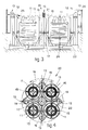
- a turret-type rotary feeder machine 20 comprises two or more reels 11 (four in this example), and a rotary support 22 rotates in a controlled manner about its axis 17 on wheels 24.
- the reels 11 cooperate with relative stands 13, which engage and guide the rods 12 and are located on an outer position and which induce in the rod 12 an upward component 25 that assists detachment of the rod 12 from the roll 11.
- the axis of rotation 17 of the support 22 lies substantially on a vertical plane passing through the line of work of the downstream usage means 14.
- the segments of the metallic shield 19 may be able to slide along each other horizontally and vertically so as to provide a total closure when the roll in question is being processed or to provide a required opening of the shield if the roll has to be tended.
- the rotary feeder machine 20 will include along its periphery a screen 26 with access doors.
- a safety device is provided to prevent rotation of the rotary support 22 when any of the access doors are open or when the shield 19 of the roll being processed is open.
- a pit 23, if provided, may be square or circular and may include or not a gangway 21 around the reels 11.
- the reels 11 being processed may include a brake device synchronized with the downstream usage machine and possibly also a start-up and/or powered device to assist the unwinding of the roll at high speeds of feed of the rod.
- the drive of the reels 11 may also be capable of an inverted movement and therefore may be employed to wind back the rod remaining in the downstream usage machines when the size of rod is changed.
- Inversion of the movement may be actuated automatically or by hand in such a way that the rod will remain protruding from the engagement and guide stand 13 by the length necessary for it to be re-engaged later by a device able to insert it into the usage machine or by the machine operator for manual insertion.
Landscapes
- Mechanical Engineering (AREA)
- Engineering & Computer Science (AREA)
- Unwinding Of Filamentary Materials (AREA)
- Specific Conveyance Elements (AREA)
- Golf Clubs (AREA)
- Supplying Of Containers To The Packaging Station (AREA)
- Replacing, Conveying, And Pick-Finding For Filamentary Materials (AREA)
- Unwinding Webs (AREA)
- Toys (AREA)
- Guides For Winding Or Rewinding, Or Guides For Filamentary Materials (AREA)
- Wire Processing (AREA)
- Bending Of Plates, Rods, And Pipes (AREA)
- Soil Working Implements (AREA)
- Jib Cranes (AREA)
- Winding, Rewinding, Material Storage Devices (AREA)
Claims (8)
- Revolverkopfartig rotierende Stangenzuführvorrichtung, die vor einer Bearbeitungsmaschine, wie eine Richtmaschine, eine Scher-und/oder Biege-und Formmaschine, angeordnet ist, wobei die Stangenzuführvorrichtung zum Tragen von Rollen von warm oder kalt hergestellten Stangen zur Bewehrung von Beton ausgebildet ist und einen drehenden Träger (22) aufweist, der eine im wesentlichen vertikale Drehachse (17) besitzt und entlang eines Umfanges mindestens zwei Trommeln (11) trägt, die Rollen (15) von Stangen halten und Drehachsen aufweisen, die im wesentlichen parallel zur Drehachse (17) des drehenden Trägers (22) verlaufen, wobei jede Trommel (11) mit einem bestimmten Gestell (13) zusammenwirkt, das die Stange ergreift und führt, durch welches Gestell (13) die Stange (15) durchgeführt wird, während sie von der Rolle abgewickelt wird, dadurch gekennzeichnet, daß das Stangengreif- und Führungsgestell (13) auf dem drehenden Träger (22) seitlich und radial außerhalb der bestimmten Trommel (11) angeordnet ist.
- Revolverkopfartig rotierende Stangenzuführvorrichtung nach Anspruch 1, bei der das Stangenführungsgestell (13) höher als die Stangenrolle (15) ist und auf die abgewickelte Stange (12) eine aufwärts gerichtete Zugwirkung längs einer Tangente an die Rolle (15) ausübt, wobei das Stangenführungsgestell (13) in einer senkrecht auf den drehenden Träger (22) vertikal verlaufenden Ebene liegt.
- Revolverkopfartig rotierende Stangenzuführvorrichtung nach einem der vorstehenden Ansprüche, die mindestens für die abzuwickelnde Rolle (15) einen Schutzschirm (19) aufweist.
- Revolverkopfartig rotierende Stangenzuführvorrichtung nach einem der vorstehenden Ansprüche, bei der zwischen den Trommelm (11) ein Laufgang (21) angeordnet ist.
- Revolverkopfartig rotierende Stangenzuführvorrichtung nach einem der vorstehenden Ansprüche, bei der die Drehachse (17) des drehenden Trägers (22) im wesentlichen in einer vertikalen Ebene liegt, die die Arbeitslinie der anschließenden Bearbeitungsmaschine (14) enthält.
- Revolverkopfartig rotierende Stangenzuführvorrichtung nach einem der vorstehenden Ansprüche, bei der die die Drehachse (17) des drehenden Trägers (22) enthaltende vertikale Ebene eine diametrale Ebene ist und auch die Durchgangsachse der Stange (12) durch das Stangenführungsgestell (13) enthält.
- Revolverkopfartig rotierende Stangenzuführvorrichtung nach einem der vorstehenden Ansprüche, deren Drehung servounterstützt und ferngesteuert ist.
- Revolverkopfartig rotierende Stangenzuführvorrichtung nach einem der vorstehenden Ansprüche, deren Drehung durch einen Computer (27) gesteuert wird, der auch die anschließende Bearbeitungsmaschine (14) steuert.
Applications Claiming Priority (2)
| Application Number | Priority Date | Filing Date | Title |
|---|---|---|---|
| IT8334790 | 1990-03-15 | ||
| IT83347A IT1239666B (it) | 1990-03-15 | 1990-03-15 | Aspo rotante a revolver |
Publications (2)
| Publication Number | Publication Date |
|---|---|
| EP0446687A1 EP0446687A1 (de) | 1991-09-18 |
| EP0446687B1 true EP0446687B1 (de) | 1994-09-07 |
Family
ID=11320513
Family Applications (1)
| Application Number | Title | Priority Date | Filing Date |
|---|---|---|---|
| EP91102615A Expired - Lifetime EP0446687B1 (de) | 1990-03-15 | 1991-02-22 | Revolverkopfartig rotierende Stangenzuführvorrichtung |
Country Status (9)
| Country | Link |
|---|---|
| US (1) | US5205508A (de) |
| EP (1) | EP0446687B1 (de) |
| JP (1) | JPH04213560A (de) |
| AT (1) | ATE110991T1 (de) |
| CA (1) | CA2038312A1 (de) |
| DE (1) | DE69103789T2 (de) |
| DK (1) | DK0446687T3 (de) |
| ES (1) | ES2058954T3 (de) |
| IT (1) | IT1239666B (de) |
Families Citing this family (12)
| Publication number | Priority date | Publication date | Assignee | Title |
|---|---|---|---|---|
| US4833172A (en) * | 1987-04-24 | 1989-05-23 | Ppg Industries, Inc. | Stretched microporous material |
| EP0587588B1 (de) * | 1991-06-04 | 1998-07-08 | Donaldson Company, Inc. | Mit fluessigkeiten behandelte polytetrafluroaethylenprodukte und ihre herstellung |
| IT1252963B (it) * | 1991-10-15 | 1995-07-07 | Piegatrici Macch Elettr | Dispositivo multifunzionale per rotoli di profilati |
| JPH0767895A (ja) * | 1993-06-25 | 1995-03-14 | Sumitomo Electric Ind Ltd | 抗菌性人工血管及び抗菌性手術用縫合糸 |
| US5810283A (en) * | 1996-08-16 | 1998-09-22 | United Technologies Automotive, Inc. | Apparatus and method for wire coil payoff |
| US5941476A (en) * | 1998-11-10 | 1999-08-24 | Copass; Nicholas S. | Portable enclosure for storage and dispensing of multiple paper rolls |
| CN109317535A (zh) * | 2018-10-23 | 2019-02-12 | 佛山市高明基业冷轧钢板有限公司 | 一种拉丝机立式开卷装置 |
| IT201800010631A1 (it) * | 2018-11-27 | 2020-05-27 | Schnell Spa | Metodo ed apparecchiatura per alimentare materiali metallici filiformi |
| EP3695914A1 (de) * | 2019-02-12 | 2020-08-19 | SMS group GmbH | Abhaspelvorrichtung und -verfahren |
| US11111101B2 (en) | 2019-03-29 | 2021-09-07 | SMS group GmbH Sitz Duesseldorf | Unreeling apparatus and method |
| DE102020212480A1 (de) | 2020-10-02 | 2022-04-07 | Wafios Aktiengesellschaft | Verfahren und Vorrichtung zum Zuführen eines langgestreckten Werkstücks zu einer Umformmaschine |
| CN113800265B (zh) * | 2021-09-16 | 2022-12-27 | 湖南高华新材料科技有限公司 | 一种箍筋收料装置 |
Family Cites Families (6)
| Publication number | Priority date | Publication date | Assignee | Title |
|---|---|---|---|---|
| US1629524A (en) * | 1923-08-16 | 1927-05-24 | Frank H Nullmeyer | Method and apparatus for drawing wire |
| US2263889A (en) * | 1939-07-18 | 1941-11-25 | George H Rose | Apparatus for unreeling bundles of coiled wire and the like |
| US2575785A (en) * | 1946-09-18 | 1951-11-20 | Morgan Construction Co | Wire handling apparatus |
| US2612324A (en) * | 1949-07-16 | 1952-09-30 | David M Yorburg | Material-selecting reel |
| FR2182594B1 (de) * | 1972-02-08 | 1974-12-06 | Normandie Ste Metallurg | |
| US3870244A (en) * | 1973-05-29 | 1975-03-11 | Rafael Tevosovich Sarkisov | Metal strip coil changing device |
-
1990
- 1990-03-15 IT IT83347A patent/IT1239666B/it active IP Right Grant
-
1991
- 1991-02-22 DK DK91102615.1T patent/DK0446687T3/da active
- 1991-02-22 AT AT91102615T patent/ATE110991T1/de active
- 1991-02-22 ES ES91102615T patent/ES2058954T3/es not_active Expired - Lifetime
- 1991-02-22 EP EP91102615A patent/EP0446687B1/de not_active Expired - Lifetime
- 1991-02-22 DE DE69103789T patent/DE69103789T2/de not_active Expired - Fee Related
- 1991-03-11 US US07/667,649 patent/US5205508A/en not_active Expired - Fee Related
- 1991-03-14 CA CA002038312A patent/CA2038312A1/en not_active Abandoned
- 1991-03-14 JP JP3049642A patent/JPH04213560A/ja active Pending
Also Published As
| Publication number | Publication date |
|---|---|
| ATE110991T1 (de) | 1994-09-15 |
| CA2038312A1 (en) | 1991-09-16 |
| DK0446687T3 (da) | 1994-10-10 |
| IT1239666B (it) | 1993-11-11 |
| US5205508A (en) | 1993-04-27 |
| EP0446687A1 (de) | 1991-09-18 |
| JPH04213560A (ja) | 1992-08-04 |
| DE69103789T2 (de) | 1995-03-30 |
| ES2058954T3 (es) | 1994-11-01 |
| DE69103789D1 (de) | 1994-10-13 |
| IT9083347A0 (it) | 1990-03-15 |
| IT9083347A1 (it) | 1991-09-15 |
Similar Documents
| Publication | Publication Date | Title |
|---|---|---|
| EP0446687B1 (de) | Revolverkopfartig rotierende Stangenzuführvorrichtung | |
| EP1126934B1 (de) | Wickelmaschine für walzgut | |
| US4355526A (en) | Method and apparatus for uncoiling and straightening material for processing thereof | |
| EP0406249A1 (de) | Anlage zum herstellen von warmgewalztem stahlband. | |
| KR100387022B1 (ko) | 미리직선화된금속와이어의원통형드럼에의포장방법및상기금속와이어가공급되는기계가공장치 | |
| JPS6347251A (ja) | 巻き取つた帯状材料のコイルを保管し、該材料の加工機械に供給する方法及び装置 | |
| US5275034A (en) | Multipurpose device for rolls of round bars of reinforced concrete | |
| CN102847749A (zh) | 一种卷取机卷筒钳口定位方法 | |
| EP0497182A1 (de) | Maschine zum Scheren des vorderen Endes und zur Entnahme von Probenstücken von einem auf eine Wickelrolle gewickelten Band | |
| US2750984A (en) | Apparatus for uncoiling sheet metal | |
| CN208880145U (zh) | 一种用于螺栓加工的放卷剪切装置 | |
| JP6514249B2 (ja) | 金属ストリップのための組み合わされた溶接および圧延プラント | |
| CN201300149Y (zh) | 一种对翘头带材自动进行导正的装置 | |
| US3470723A (en) | Strand handling apparatus | |
| CN212976328U (zh) | 一种低摩擦的钢丝卷绕装置 | |
| US4094049A (en) | Casting rolling mill for wire | |
| CN224000771U (zh) | 一种导爆索用盘卷装置 | |
| US3595052A (en) | Pipe bending device | |
| CN101480666A (zh) | 一种对翘头带材自动进行导正的方法及装置 | |
| EP0509232A1 (de) | Ausricht- und Zieheinrichtung, einer Haspeleinrichtung nachgeschaltet | |
| CN213134549U (zh) | 一种安全警示钢丝卷绕装置 | |
| SU1030107A1 (ru) | Агрегат дл резки стальных полос | |
| CN212976329U (zh) | 一种钢丝卷绕装置 | |
| PL190054B1 (pl) | Sposób wytwarzania taśmy metalowej zwijanej w krąg i urządzenie do wytwarzania taśmy metalowej zwijanej w krąg | |
| CN224159540U (zh) | 一种带钢卧卷的手动打包装置 |
Legal Events
| Date | Code | Title | Description |
|---|---|---|---|
| PUAI | Public reference made under article 153(3) epc to a published international application that has entered the european phase |
Free format text: ORIGINAL CODE: 0009012 |
|
| AK | Designated contracting states |
Kind code of ref document: A1 Designated state(s): AT BE CH DE DK ES FR GB GR LI LU NL SE |
|
| 17P | Request for examination filed |
Effective date: 19920221 |
|
| 17Q | First examination report despatched |
Effective date: 19930605 |
|
| GRAA | (expected) grant |
Free format text: ORIGINAL CODE: 0009210 |
|
| AK | Designated contracting states |
Kind code of ref document: B1 Designated state(s): AT BE CH DE DK ES FR GB GR LI LU NL SE |
|
| REF | Corresponds to: |
Ref document number: 110991 Country of ref document: AT Date of ref document: 19940915 Kind code of ref document: T |
|
| ET | Fr: translation filed | ||
| REG | Reference to a national code |
Ref country code: DK Ref legal event code: T3 |
|
| REF | Corresponds to: |
Ref document number: 69103789 Country of ref document: DE Date of ref document: 19941013 |
|
| REG | Reference to a national code |
Ref country code: ES Ref legal event code: FG2A Ref document number: 2058954 Country of ref document: ES Kind code of ref document: T3 |
|
| REG | Reference to a national code |
Ref country code: GR Ref legal event code: FG4A Free format text: 3013416 |
|
| EAL | Se: european patent in force in sweden |
Ref document number: 91102615.1 |
|
| PLBE | No opposition filed within time limit |
Free format text: ORIGINAL CODE: 0009261 |
|
| STAA | Information on the status of an ep patent application or granted ep patent |
Free format text: STATUS: NO OPPOSITION FILED WITHIN TIME LIMIT |
|
| 26N | No opposition filed | ||
| PGFP | Annual fee paid to national office [announced via postgrant information from national office to epo] |
Ref country code: GR Payment date: 19970128 Year of fee payment: 7 |
|
| PGFP | Annual fee paid to national office [announced via postgrant information from national office to epo] |
Ref country code: CH Payment date: 19970130 Year of fee payment: 7 |
|
| PGFP | Annual fee paid to national office [announced via postgrant information from national office to epo] |
Ref country code: LU Payment date: 19970206 Year of fee payment: 7 |
|
| PGFP | Annual fee paid to national office [announced via postgrant information from national office to epo] |
Ref country code: BE Payment date: 19970212 Year of fee payment: 7 |
|
| PGFP | Annual fee paid to national office [announced via postgrant information from national office to epo] |
Ref country code: GB Payment date: 19970213 Year of fee payment: 7 |
|
| PGFP | Annual fee paid to national office [announced via postgrant information from national office to epo] |
Ref country code: SE Payment date: 19970217 Year of fee payment: 7 Ref country code: DK Payment date: 19970217 Year of fee payment: 7 |
|
| PGFP | Annual fee paid to national office [announced via postgrant information from national office to epo] |
Ref country code: AT Payment date: 19970218 Year of fee payment: 7 |
|
| PGFP | Annual fee paid to national office [announced via postgrant information from national office to epo] |
Ref country code: NL Payment date: 19970228 Year of fee payment: 7 |
|
| PGFP | Annual fee paid to national office [announced via postgrant information from national office to epo] |
Ref country code: DE Payment date: 19970429 Year of fee payment: 7 |
|
| PGFP | Annual fee paid to national office [announced via postgrant information from national office to epo] |
Ref country code: FR Payment date: 19980130 Year of fee payment: 8 |
|
| PGFP | Annual fee paid to national office [announced via postgrant information from national office to epo] |
Ref country code: ES Payment date: 19980205 Year of fee payment: 8 |
|
| PG25 | Lapsed in a contracting state [announced via postgrant information from national office to epo] |
Ref country code: LU Free format text: LAPSE BECAUSE OF NON-PAYMENT OF DUE FEES Effective date: 19980222 Ref country code: GB Free format text: LAPSE BECAUSE OF NON-PAYMENT OF DUE FEES Effective date: 19980222 Ref country code: AT Free format text: LAPSE BECAUSE OF NON-PAYMENT OF DUE FEES Effective date: 19980222 |
|
| PG25 | Lapsed in a contracting state [announced via postgrant information from national office to epo] |
Ref country code: SE Free format text: LAPSE BECAUSE OF NON-PAYMENT OF DUE FEES Effective date: 19980223 |
|
| PG25 | Lapsed in a contracting state [announced via postgrant information from national office to epo] |
Ref country code: LI Free format text: LAPSE BECAUSE OF NON-PAYMENT OF DUE FEES Effective date: 19980228 Ref country code: GR Free format text: LAPSE BECAUSE OF NON-PAYMENT OF DUE FEES Effective date: 19980228 Ref country code: CH Free format text: LAPSE BECAUSE OF NON-PAYMENT OF DUE FEES Effective date: 19980228 Ref country code: BE Free format text: LAPSE BECAUSE OF NON-PAYMENT OF DUE FEES Effective date: 19980228 |
|
| PG25 | Lapsed in a contracting state [announced via postgrant information from national office to epo] |
Ref country code: DK Free format text: LAPSE BECAUSE OF NON-PAYMENT OF DUE FEES Effective date: 19980302 |
|
| BERE | Be: lapsed |
Owner name: MACCHINE ELETTRONICHE PIEGATRICI S.P.A. MEP Effective date: 19980228 |
|
| PG25 | Lapsed in a contracting state [announced via postgrant information from national office to epo] |
Ref country code: NL Free format text: LAPSE BECAUSE OF NON-PAYMENT OF DUE FEES Effective date: 19980901 |
|
| GBPC | Gb: european patent ceased through non-payment of renewal fee |
Effective date: 19980222 |
|
| REG | Reference to a national code |
Ref country code: CH Ref legal event code: PL |
|
| EUG | Se: european patent has lapsed |
Ref document number: 91102615.1 |
|
| NLV4 | Nl: lapsed or anulled due to non-payment of the annual fee |
Effective date: 19980901 |
|
| PG25 | Lapsed in a contracting state [announced via postgrant information from national office to epo] |
Ref country code: DE Free format text: LAPSE BECAUSE OF NON-PAYMENT OF DUE FEES Effective date: 19981103 |
|
| PG25 | Lapsed in a contracting state [announced via postgrant information from national office to epo] |
Ref country code: ES Free format text: LAPSE BECAUSE OF NON-PAYMENT OF DUE FEES Effective date: 19990223 |
|
| PG25 | Lapsed in a contracting state [announced via postgrant information from national office to epo] |
Ref country code: FR Free format text: LAPSE BECAUSE OF NON-PAYMENT OF DUE FEES Effective date: 19991029 |
|
| REG | Reference to a national code |
Ref country code: FR Ref legal event code: ST |
|
| REG | Reference to a national code |
Ref country code: DK Ref legal event code: EBP |
|
| REG | Reference to a national code |
Ref country code: ES Ref legal event code: FD2A Effective date: 20010503 |