EP0446501A1 - Vorrichtung zur Verringerung der magnetischen Strahlung ausserhalb einer Kathodenstrahlanzeigeeinrichtung - Google Patents
Vorrichtung zur Verringerung der magnetischen Strahlung ausserhalb einer Kathodenstrahlanzeigeeinrichtung Download PDFInfo
- Publication number
- EP0446501A1 EP0446501A1 EP90302248A EP90302248A EP0446501A1 EP 0446501 A1 EP0446501 A1 EP 0446501A1 EP 90302248 A EP90302248 A EP 90302248A EP 90302248 A EP90302248 A EP 90302248A EP 0446501 A1 EP0446501 A1 EP 0446501A1
- Authority
- EP
- European Patent Office
- Prior art keywords
- ring
- magnetic field
- tube
- field
- deflection
- Prior art date
- Legal status (The legal status is an assumption and is not a legal conclusion. Google has not performed a legal analysis and makes no representation as to the accuracy of the status listed.)
- Ceased
Links
- 230000001603 reducing effect Effects 0.000 title claims abstract description 17
- 230000005855 radiation Effects 0.000 title description 15
- 230000000694 effects Effects 0.000 claims abstract description 18
- 239000000463 material Substances 0.000 claims abstract description 8
- 239000002245 particle Substances 0.000 claims abstract description 3
- 229910000859 α-Fe Inorganic materials 0.000 description 20
- 230000005415 magnetization Effects 0.000 description 12
- 238000010586 diagram Methods 0.000 description 11
- 230000035699 permeability Effects 0.000 description 7
- 238000010894 electron beam technology Methods 0.000 description 6
- 238000004804 winding Methods 0.000 description 4
- 230000008878 coupling Effects 0.000 description 3
- 238000010168 coupling process Methods 0.000 description 3
- 238000005859 coupling reaction Methods 0.000 description 3
- 230000010287 polarization Effects 0.000 description 3
- 238000002474 experimental method Methods 0.000 description 2
- 229910000595 mu-metal Inorganic materials 0.000 description 2
- 238000000926 separation method Methods 0.000 description 2
- 230000002411 adverse Effects 0.000 description 1
- 230000003247 decreasing effect Effects 0.000 description 1
- 230000001419 dependent effect Effects 0.000 description 1
- 238000009413 insulation Methods 0.000 description 1
- 238000004519 manufacturing process Methods 0.000 description 1
- 239000007787 solid Substances 0.000 description 1
- 238000010408 sweeping Methods 0.000 description 1
Images


Classifications
-
- H—ELECTRICITY
- H01—ELECTRIC ELEMENTS
- H01J—ELECTRIC DISCHARGE TUBES OR DISCHARGE LAMPS
- H01J29/00—Details of cathode-ray tubes or of electron-beam tubes of the types covered by group H01J31/00
- H01J29/003—Arrangements for eliminating unwanted electromagnetic effects, e.g. demagnetisation arrangements, shielding coils
-
- H—ELECTRICITY
- H01—ELECTRIC ELEMENTS
- H01J—ELECTRIC DISCHARGE TUBES OR DISCHARGE LAMPS
- H01J29/00—Details of cathode-ray tubes or of electron-beam tubes of the types covered by group H01J31/00
- H01J29/46—Arrangements of electrodes and associated parts for generating or controlling the ray or beam, e.g. electron-optical arrangement
- H01J29/70—Arrangements for deflecting ray or beam
-
- H—ELECTRICITY
- H01—ELECTRIC ELEMENTS
- H01J—ELECTRIC DISCHARGE TUBES OR DISCHARGE LAMPS
- H01J2229/00—Details of cathode ray tubes or electron beam tubes
- H01J2229/0007—Elimination of unwanted or stray electromagnetic effects
- H01J2229/0015—Preventing or cancelling fields leaving the enclosure
Definitions
- the present invention relates to CRT display apparatus, and more particularly relates to apparatus for reducing unwanted magnetic radiation external to a cathode ray tube display device without affecting the intended electron beam deflection magnetic field within the device.
- Cathode ray tube (CRT) display apparatus generally has associated coils, or yokes, to provide a varying magnetic field for electron beam deflection, for example for a raster scan.
- this magnetic field also extends around the outside of the CRT and beyond the display apparatus. This external magnetic field serves no useful purpose and an effort is frequently made to reduce this unwanted magnetic field.
- the unwanted frequency range is from 1K to 350K hertz (VLF).
- Helmholtz coils to provide reduction of this radiation.
- the Helmholtz coils are "on top” and “below” a saddle-shaped deflection yoke.
- the Helmholtz coils are behind the yoke.
- the Helmholtz coils are coupled to the deflection coils and an EMF is induced in the Helmholtz coils, giving rise to a magnetic field which tends to cancel the unwanted radiated magnetic field.
- EMF EMF
- EP-A- 302995 discloses the use of a magnetic shunt in the form of a ring of magnetic permeable material located between the deflection coil and the viewing screen of a CRT display apparatus in order to reduce unwanted magnetic radiation which extends outside the CRT.
- the object of the present invention is to provide an improved arrangement for reducing the unwanted magnetic radiation which extends outside a CRT display apparatus.
- the present invention relates to a cathode ray tube display apparatus
- a cathode ray tube display apparatus comprising a cathode ray tube including a viewing screen, means for producing a charged particle beam directed at the screen from the rear thereof and aligned with a central axis of the apparatus, deflection coils generating a first magnetic field which extends within the tube for deflecting the beam across the screen and a second magnetic field which extends outside the tube, and means for reducing the second magnetic field which extends outside the tube including a ring of magnetically permeable material centred substantially on the central axis and positioned adjacent to the coil.
- the apparatus is characterised in that the means for reducing the second magnetic field comprises at least one pair of wire loops extending round and through the ring and electrically connected to the deflection coils so as to induce a magnetic field within the ring to counteract and reduce the second magnetic field which extends outside the tube but to have negligible effect on the first magnetic field within the tube.
- Fig. 1 shows the pertinent portions of the deflection yoke of a CRT display apparatus 10 which includes a CRT 12, having a front screen 14, and upper and lower horizontal deflection coils 16, 18.
- the deflection coils 16, 18 generate a varying magnetic field between them, inside CRT 12, to deflect an electron beam within the tube 12 for horizontal sweeping across the fact of the screen 14, as is well known in the art.
- Fig. 2 is a simplified diagram of one winding each from the upper and lower deflection coils 16, 18 of Fig. 1.
- loop 20 is a single loop from coil 16
- loop 22 is a single loop from coil 18.
- a current i flows through each of the coils so as to generate the above described varying magnetic field for horizontal deflection of the electron beam.
- X, Y, and Z are axes having their common origin in the plane of circumferential coil portions 34, 38 of loops 20, 22 and centrally located between them.
- the X axis coincides with the central axis of CRT 12 (Fig. 1). Note that the upper and lower loops 20, 22 are symmetrical about the X-Z and Y-Z planes.
- the upper and lower loops 20, 22 are interconnected to produce a dipole field on the Z axis as is known.
- the B field is given by: where J is the current, R is the direction and R is the distance to a point of interest P on the Z axis. This equation is used in computing the field distribution of Figs. 3 and 6 to 11.
- FIG. 3 A plot of the computed B field distribution of an air core horizontal deflection coil, such as is shown in Fig. 1, without any high permeability material, like ferrite shielding, is shown in Fig. 3.
- the actual B field is a directional field, and the plot shown in Fig. 3 shows only the magnitude, or intensity, of such a magnetic field along the Z axis.
- the units depicted in the horizontal axis are centimetres, while the units in the vertical axis are gauss.
- the curve reflects a typical coil having current flowing so as to produce a field which deflects a 20 kilovolt electron beam to an angle of about 40 degrees.
- Curves A, B, and C of Fig. 3 represent the total field, the partial field from the axial wires and the partial field from the end turns, respectively.
- Curve A is the magnitude along the Z axis of the vector sum of the fields represented by curves B and C.
- the field can be in the range of approximately 1,000 - 2,000 nano- Tesla. Clearly, this is not a very large magnetic field. However, in accordance with the arrangements described herein this field can be reduced to an even smaller quantity. In actual experiments using the arrangements described below, reduction to below 200 nano-tesla at 55 centimetres was measured.
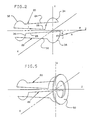
- Fig. 4 shows the apparatus 10 of Fig. 1 having added thereto a ring 50 of linear ferrite operating as a magnetic shunt, in accordance with the arrangement described in EP-A- 302995.
- Fig. 5 shows the loops 20, 22 of Fig. 2, with the ferrite ring 50 disposed in front thereof, to illustrate the relative shape and position of ring 50.
- Ring 50 is made from linear ferrite.
- Linear ferrite is a well known material commonly used in transformer and yoke production.
- the ring 50 has a relatively high magnetic permeability, ( ⁇ above 2,500). It also has a high volume resistivity, for example 1 Meg Ohm or more per cubic centimetre. The high resistivity value keeps eddy currents induced in the ring at a minimum. Otherwise the loading effects on the yoke would result in a need for more energy to drive the yoke. While embodiments could be constructed, for example out of conventional ⁇ laminates, having this loading effect, it was deemed desirable to keep the eddy currents low, and avoid this loading effect in the arrangement described.
- the cross section of the ring 50 is large enough to avoid saturation.
- Fig. 6 is a set of curves, on the same set of axes as those of Fig. 3, showing the effect along the Z axis on the net field A shown in Fig. 3 of a flat ring, such as ring 50 in Fig. 4.
- Curve A in Fig. 6 is the same as curve A in Fig. 3.
- Curve D in Fig. 6 represents the field contribution from the magnetization effect of the ring 50, while curve E represents the resultant curve from the combination of curves A and D.
- Fig. 7 a set of curves is shown in Fig. 7 including curve D, and the end turn magnetic field component C.
- Curve C is the same curve C as shown in Fig. 3.
- Curve F is a curve representing the resultant field from the combination of curves D and C. Note that in Fig. 7 the horizontal axis scale is the same in Figs. 3 and 7 while the vertical axis scale has been expanded, to aid in clarity.
- curve D is the theoretical field produced by the ring 50 alone. This is an intrinsic field which is created by the magnetization force of the end turn field. It should be noted that the presence of the ring attenuates the end turn field. The degree of attenuation is controlled by the variables such as ring dimensions and ring yoke separation, as is discussed in more detail below. It should be further noted that the end turn field combines with the main deflection field in the area in front of the CRT screen, to form the net measurable residual field whose reduction is an object of this invention. At optimum attenuation, the modified end turn field F is equal in magnitude but opposite in direction to the main deflection field, resulting in a zero vector sum. As a practical matter, the net measurable residual field in front of the CRT screen can never be reduced to zero. However, by application of the principles described in EP-A- 302995, this field can be reduced to very small levels.
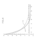
- Fig. 8 The portion of Fig. 6 beyond approximately 2.5 centimetres to the right thereof along the Z axis is shown in Fig. 8. In order to see clearly the curve behaviour in that region, the scale is expanded in the vertical direction as compared with Fig. 6. Curves A and E are described in connection with Fig. 6. Curve D is not shown in this figure in the interest of providing more clarity for curves A and E. Note that curve E is very nearly at a zero field magnitude at approximately 9.5 centimetres along the Z axis.
- the compensated curve E is for a typical CRT-yoke configuration, having a ring 50 of ferrite with a permeability of 1,000 - 3,000 and high volume resistivity, and having an inner dimension of 4 centimetres, a thickness of 0.2 centimetres, and a width of 1 centimetre, placed at a distance of 0.4 centimetres from the end of the yoke.
- the term "width" of the ring refers to its radial extent from inner surface to outer surface.
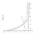
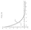
- Figs. 9 - 11 are plots like the plot shown in Fig. 8, for slightly different ring configurations from the configuration producing the curves of Fig. 8.
- all of the parameters for the ring 50 are the same as those corresponding to Fig. 8, except the distance of the ring from the end of the yoke.
- the curves correspond to a configuration in which this dimension is 0.3 centimetres. It will be appreciated that this reveals over-compensation, as the curve E′ is slightly above the horizontal axis, for example at 9.5 centimetres, and slightly above curve E in Fig. 8.
- Fig. 10 The curves of Fig. 10 are for a configuration in which the dimensions of the ring 50 are the same as those corresponding to Fig. 8, but wherein the inner surface radius is 5 centimetres, instead of 4 centimetres. It can be seen that significantly less compensation is provided, as curve E ⁇ is here below the horizontal axis.
- Fig. 11 shows a curve for a configuration wherein the dimensions of ring 50 are as in Fig. 8, but wherein the distance of the ring from the end of the yoke is 0.6 centimetres, instead of 0.4 centimetres. It can be seen that slightly less compensation is provided, causing curve E′′′ to cross the horizontal axis at 9.5 centimetres along the Z axis. This was deemed to represent optimum compensation.
- the CRT tube 10 has air core horizontal deflection coils without any high permeability shielding about the neck of the tube.
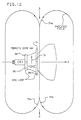
- the direction of the horizontal deflection field to move the electron beam toward the right edge of the screen as viewed from the front is represented by arrow 70 in Fig. 12.
- the horizontal deflection coils have ferrite shielding (ferrite core) 68 about the horizontal deflection coils as shown in Fig. 12.
- ferrite shielding ferrite core
- vertical deflection coils (not shown) positioned about the horizontal deflection coils and under the ferrite core.
- the magnetic field produced by the horizontal coils with the end loops 32, 34, 36 and 38 extending beyond the ferrite core includes a radiated field which is in the form of a dipole centred forward of the deflection coil loop nearest the screen as shown by arrows 70a in Fig. 12 and this radiated field extends outside the CRT display apparatus.
- the ferrite core 68 reverses the polarity of the radiated field.
- a ferrite ring 50 as shown and illustrated in Fig. 13 is mounted forward of the horizontal deflection coils near the centre of the radiated field produced by the horizontal coils.
- the manner in which this ring compensates for or reduces the radiated field without measurably affecting the deflection field is illustrated in connection with Figs. 14 and 15.
- Fig. 14 is a sketch of a plan view of the deflection coil 16, ferrite core 68 and ferrite ring 50 illustrating the deflection current in the deflection coil, the magnetization currents induced in the ferrite components and the resulting magnetic fields.
- Fig. 15 is a front view of the arrangement illustrated in Fig. 14.
- the counterclockwise current in the horizontal deflection coil 16 seen in the plan view is represented by 71.
- the magnetic field produced by this current is represented by O H and is directed up out of the Figure towards the viewer. This corresponds to the arrow 70 in Fig. 12.
- the ferrite core 68 is magnetically coupled to the deflection coil 16 and there is induced in the core 68 an even stronger equivalent magnetization current M1 represented by the heavy lines 72.
- the induced current 72 circulates in the opposite direction (clockwise in Fig. 14) with the currents along the adjacent surfaces of the coil and the core flowing in the same direction.
- the result is a first magnetic field X1 (with a direction into the Figure as viewed) in the centre of the core.
- the field X1 combines with field O H and produces a net radiated field O1 equivalent to the radiated field 70a of Fig. 12 which is the vector sum of O H and X1 in front of the ring 50.
- the radiated field O1 is a dipole field and is the major component of the unwanted magnetic radiation extending outside the CRT display apparatus.
- the exposed end turns of the deflection coils 16, 18 are also radiating a minor quadrapole magnetic field which is designated an X E .
- Symbols "X" and "O" which are consistent with the sign convention established earlier where X means the field is pointing down into the Figure, and O means the field is pointing up towards the viewer.
- the sum of X1 and X E is the total radiated magnetic field without considering the effect of the ring 50.
- the front end-turns of the horizontal deflection coils 16, 18 induce equivalent magnetization currents M3 in the ring 50 in a clockwise direction.
- the resulting field is pointing down within the ring X3 and pointing up outside of the ring O3 as illustrated in Fig. 14.
- the polarization of this field is also shown in Fig. 15 with letters "N′" (north) and "S" (south).
- the induced field X1 in the yoke shield 68 sets up a dipole magnetization O2 in the ring 50 which opposes the radiated dipole field O1.
- the quadrapole component X E of the radiated field due to the exposed end-turns of the horizontal deflection coils 16, 18 induces a quadrapole magnetization in the ring 50 which cancels the radiated quadrapole field.
- Variables such as the thickness, inside diameter, outside diameter and permeability of the ring 50 and yoke-ring separation can be selected so as to tune for optimum performance (reduction of the unwanted radiated field).
- the lower limits of the ring dimensions are dictated by the given CRT and yoke combination. In practice, the tendency is to bring the ring 50 as close to the front of the yoke as possible without adversely effecting the deflection field within the tube. This reduces the ring dimensions and ensures minimum cost.
- the ring has a lower limit of permeability of about 1,000 with the ring placed closest to the yoke. The higher the permeability the greater the distance the ring can be from the yoke.
- a ferrite ring 50 of ordinary linear ferrite was provided, having a ⁇ of approximately 1,000 - 3,000 and a volume of resistivity of greater than 1 meg ohm per cc, with ring dimensions of: an inner dimension of 4-3/8 inches (11 cms), a width of 3/8 inches (1 cm), and a thickness of 1/8 inch (0.3 cm).
- This ring was found to produce excellent radiated field cancellation effects when it was placed against the circumferential wire portions (end closest to the screen) of the yoke provided with this CRT display apparatus with spacing resulting only from the insulation of the yoke wires.
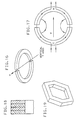
- Embodiments of the ring 50 may be made with conventional ⁇ metal laminates, yielding rings having a cross-section as shown in Fig. 18.
- Fig. 19 shows a hexagonally shaped ring, representing a still further embodiment for use with, for example, a hexagonally configured yoke.
- Fig. 20 is a top view of the deflection yoke, the tube and the ring.
- Fig. 21 is an electrical diagram showing the terminals. Terminal 1 is coupled to one end of the driver for the deflection coils and terminal 4 is the return to the driver. "Upper” refers to the upper yoke coil and “Lower” refers to the lower yoke coil.
- Fig. 22 illustrates an upper yoke coil 220 and a lower yoke coil 221.
- the first loop 210 begins at terminal 1 on the rear bundle terminal, passes clockwise round and through the ring 50 and terminates at terminal 2.
- the upper and lower yoke coils are connected in parallel at one end to terminal 2 and at the other end to terminal 3.
- the second loop 211 extends from terminal 3 and passes clockwise round and through the ring 50 on the opposite side of the ring from loop 210 (diametrically opposite positions in the horizontal plane) and terminates at terminal 4.
- the loops 210, 211 are in series with each other and in series with the parallel yoke coils.
- An end view of the ring 50 as seen from the screen with the loops 210, 211 is illustrated in Fig. 23. Note the directions of arrows 215 and 216 match in Figs. 20 and 22.
- compensation for the quadrapole radiated field can be by the loops 210, 211 passing round and through the ring 50 and also through quadrature placed holes 218 in the ring 50 as shown in Figs. 24 and 25 before returning to the terminals 1, 2, 3, 4 illustrated in Fig. 20.
- the ring 50 may be any of the shapes, sizes, dimensions and material discussed herein and that the number of loop turns can be selected according to the required coupling to achieve the desired reduced radiation.
Landscapes
- Physics & Mathematics (AREA)
- Electromagnetism (AREA)
- Video Image Reproduction Devices For Color Tv Systems (AREA)
Applications Claiming Priority (2)
| Application Number | Priority Date | Filing Date | Title |
|---|---|---|---|
| US32247089A | 1989-03-13 | 1989-03-13 | |
| US322470 | 1989-03-13 |
Publications (1)
| Publication Number | Publication Date |
|---|---|
| EP0446501A1 true EP0446501A1 (de) | 1991-09-18 |
Family
ID=23255050
Family Applications (1)
| Application Number | Title | Priority Date | Filing Date |
|---|---|---|---|
| EP90302248A Ceased EP0446501A1 (de) | 1989-03-13 | 1990-03-02 | Vorrichtung zur Verringerung der magnetischen Strahlung ausserhalb einer Kathodenstrahlanzeigeeinrichtung |
Country Status (9)
| Country | Link |
|---|---|
| EP (1) | EP0446501A1 (de) |
| JP (1) | JPH02299134A (de) |
| KR (1) | KR920005005B1 (de) |
| CN (1) | CN1046636A (de) |
| AU (1) | AU623227B2 (de) |
| BR (1) | BR9001146A (de) |
| CA (1) | CA2011508A1 (de) |
| MY (1) | MY107095A (de) |
| NZ (1) | NZ232662A (de) |
Citations (3)
| Publication number | Priority date | Publication date | Assignee | Title |
|---|---|---|---|---|
| EP0258891A2 (de) * | 1986-09-05 | 1988-03-09 | Murata Manufacturing Co., Ltd. | Ablenkeinheit mit Mitteln zur Unterdrückung ungewünschter Abstrahlung |
| WO1988006346A1 (en) * | 1987-02-19 | 1988-08-25 | Hantarex Spa | Device for limiting the magnetic emission in cathode ray tube monitors |
| EP0302995A1 (de) * | 1987-08-13 | 1989-02-15 | International Business Machines Corporation | Magnetischer Shunt für Ablenkjoche |
Family Cites Families (4)
| Publication number | Priority date | Publication date | Assignee | Title |
|---|---|---|---|---|
| JPS60103382A (ja) * | 1983-11-10 | 1985-06-07 | 積水樹脂株式会社 | 模様付塗装柵の模様寸法取り方法 |
| DE3439808A1 (de) * | 1984-10-31 | 1986-04-30 | Standard Elektrik Lorenz Ag, 7000 Stuttgart | Ablenksystem fuer farbbildroehren |
| JPS6293841A (ja) * | 1985-10-17 | 1987-04-30 | Mitsubishi Electric Corp | 不要輻射防止装置 |
| SE456056B (sv) * | 1986-12-10 | 1988-08-29 | Telub Holding Ab | Anordning vid bildror for att reducera den magnetiska feltstyrkan i bildrorets omgivning |
-
1990
- 1990-02-14 MY MYPI90000246A patent/MY107095A/en unknown
- 1990-02-23 NZ NZ232662A patent/NZ232662A/en unknown
- 1990-02-26 AU AU50182/90A patent/AU623227B2/en not_active Ceased
- 1990-02-26 KR KR1019900002400A patent/KR920005005B1/ko not_active Expired
- 1990-03-02 EP EP90302248A patent/EP0446501A1/de not_active Ceased
- 1990-03-03 CN CN90101129A patent/CN1046636A/zh active Pending
- 1990-03-05 CA CA002011508A patent/CA2011508A1/en not_active Abandoned
- 1990-03-12 BR BR909001146A patent/BR9001146A/pt unknown
- 1990-03-12 JP JP2058251A patent/JPH02299134A/ja active Pending
Patent Citations (3)
| Publication number | Priority date | Publication date | Assignee | Title |
|---|---|---|---|---|
| EP0258891A2 (de) * | 1986-09-05 | 1988-03-09 | Murata Manufacturing Co., Ltd. | Ablenkeinheit mit Mitteln zur Unterdrückung ungewünschter Abstrahlung |
| WO1988006346A1 (en) * | 1987-02-19 | 1988-08-25 | Hantarex Spa | Device for limiting the magnetic emission in cathode ray tube monitors |
| EP0302995A1 (de) * | 1987-08-13 | 1989-02-15 | International Business Machines Corporation | Magnetischer Shunt für Ablenkjoche |
Also Published As
| Publication number | Publication date |
|---|---|
| KR920005005B1 (ko) | 1992-06-22 |
| AU5018290A (en) | 1990-09-13 |
| MY107095A (en) | 1995-09-30 |
| JPH02299134A (ja) | 1990-12-11 |
| AU623227B2 (en) | 1992-05-07 |
| NZ232662A (en) | 1992-01-29 |
| CN1046636A (zh) | 1990-10-31 |
| CA2011508A1 (en) | 1990-09-13 |
| KR900015235A (ko) | 1990-10-26 |
| BR9001146A (pt) | 1991-03-05 |
Similar Documents
| Publication | Publication Date | Title |
|---|---|---|
| EP0258891B1 (de) | Ablenkeinheit mit Mitteln zur Unterdrückung ungewünschter Abstrahlung | |
| US4740758A (en) | Apparatus for generating a magnetic field in a volume having bodies influencing the field pattern | |
| CA1276674C (en) | Picture display device with interference suppression coils | |
| US4943753A (en) | Magnetic shunt for deflection yokes | |
| EP0346972B1 (de) | Bildwiedergabeanordnung mit ausgleichsspulenbestückten Kernmitteln | |
| US4864192A (en) | CRT magnetic field compensation | |
| EP0327161B1 (de) | Bildwiedergabeanordnung mit einem Ausgleichsspulenbestückten, magnetisierbaren Kernmittel | |
| US3534208A (en) | Cathode ray tube having three in-line guns and center beam convergence shield modifying center beam raster size | |
| EP0446501A1 (de) | Vorrichtung zur Verringerung der magnetischen Strahlung ausserhalb einer Kathodenstrahlanzeigeeinrichtung | |
| CA1306281C (en) | Magnetic shunt for deflection yokes | |
| EP0146267A2 (de) | Magnetische Anlage | |
| US5200673A (en) | Method and device for suppression of leakage of magnetic flux in display apparatus | |
| EP0401831B1 (de) | Kathodenstrahlrohreinrichtung zur Verringerung von magnetischen Streuflüssen ausserhalb der Einrichtung | |
| US5432492A (en) | Deflection yoke apparatus with auxiliar coils to compensensate magnetic leakage | |
| JP3569136B2 (ja) | ブラウン管の磁気シールド装置 | |
| JPH0246085A (ja) | 陰極線管デイスプレー装置 | |
| EP0520556A1 (de) | Bildwiedergabeanordnung mit Ausgleichspulen | |
| JPH04245149A (ja) | 陰極線管装置 | |
| Meinander | Generation of magnetic fields for accelerators with permanent magnets | |
| GB1597604A (en) | Lateral convergence assembly for cathode ray tube | |
| JPH01154442A (ja) | 陰極線管表示装置 | |
| EP0540096A1 (de) | Ablenkjochvorrichtung mit Mitteln zur Verringerung von Leckmagnetfeldern | |
| JPH01154441A (ja) | 偏向ヨーク装置 | |
| JPH01253142A (ja) | 偏向ヨーク装置 | |
| JPH01225047A (ja) | カラー受像管装置 |
Legal Events
| Date | Code | Title | Description |
|---|---|---|---|
| PUAI | Public reference made under article 153(3) epc to a published international application that has entered the european phase |
Free format text: ORIGINAL CODE: 0009012 |
|
| 17P | Request for examination filed |
Effective date: 19901213 |
|
| AK | Designated contracting states |
Kind code of ref document: A1 Designated state(s): BE CH DE ES FR GB LI NL SE |
|
| 17Q | First examination report despatched |
Effective date: 19931102 |
|
| STAA | Information on the status of an ep patent application or granted ep patent |
Free format text: STATUS: THE APPLICATION HAS BEEN REFUSED |
|
| 18R | Application refused |
Effective date: 19940425 |