EP0346972B1 - Bildwiedergabeanordnung mit ausgleichsspulenbestückten Kernmitteln - Google Patents
Bildwiedergabeanordnung mit ausgleichsspulenbestückten Kernmitteln Download PDFInfo
- Publication number
- EP0346972B1 EP0346972B1 EP89201464A EP89201464A EP0346972B1 EP 0346972 B1 EP0346972 B1 EP 0346972B1 EP 89201464 A EP89201464 A EP 89201464A EP 89201464 A EP89201464 A EP 89201464A EP 0346972 B1 EP0346972 B1 EP 0346972B1
- Authority
- EP
- European Patent Office
- Prior art keywords
- plane
- core means
- core
- coil
- compensation
- Prior art date
- Legal status (The legal status is an assumption and is not a legal conclusion. Google has not performed a legal analysis and makes no representation as to the accuracy of the status listed.)
- Expired - Lifetime
Links
- 230000005855 radiation Effects 0.000 claims description 25
- 238000010894 electron beam technology Methods 0.000 claims description 6
- 239000000696 magnetic material Substances 0.000 claims description 3
- 238000004804 winding Methods 0.000 claims description 3
- OAICVXFJPJFONN-UHFFFAOYSA-N Phosphorus Chemical compound [P] OAICVXFJPJFONN-UHFFFAOYSA-N 0.000 claims description 2
- 230000001154 acute effect Effects 0.000 claims description 2
- 239000000463 material Substances 0.000 description 4
- 230000035945 sensitivity Effects 0.000 description 4
- 230000006698 induction Effects 0.000 description 2
- 238000000034 method Methods 0.000 description 2
- 238000010168 coupling process Methods 0.000 description 1
- 238000005859 coupling reaction Methods 0.000 description 1
- 230000003247 decreasing effect Effects 0.000 description 1
- 230000001419 dependent effect Effects 0.000 description 1
- 238000010586 diagram Methods 0.000 description 1
- 230000004907 flux Effects 0.000 description 1
- 230000002452 interceptive effect Effects 0.000 description 1
- 230000001681 protective effect Effects 0.000 description 1
- 230000007704 transition Effects 0.000 description 1
- 229910000859 α-Fe Inorganic materials 0.000 description 1
Images


Classifications
-
- H—ELECTRICITY
- H01—ELECTRIC ELEMENTS
- H01J—ELECTRIC DISCHARGE TUBES OR DISCHARGE LAMPS
- H01J29/00—Details of cathode-ray tubes or of electron-beam tubes of the types covered by group H01J31/00
- H01J29/46—Arrangements of electrodes and associated parts for generating or controlling the ray or beam, e.g. electron-optical arrangement
- H01J29/70—Arrangements for deflecting ray or beam
- H01J29/72—Arrangements for deflecting ray or beam along one straight line or along two perpendicular straight lines
- H01J29/76—Deflecting by magnetic fields only
-
- H—ELECTRICITY
- H01—ELECTRIC ELEMENTS
- H01J—ELECTRIC DISCHARGE TUBES OR DISCHARGE LAMPS
- H01J29/00—Details of cathode-ray tubes or of electron-beam tubes of the types covered by group H01J31/00
- H01J29/003—Arrangements for eliminating unwanted electromagnetic effects, e.g. demagnetisation arrangements, shielding coils
-
- H—ELECTRICITY
- H01—ELECTRIC ELEMENTS
- H01J—ELECTRIC DISCHARGE TUBES OR DISCHARGE LAMPS
- H01J2229/00—Details of cathode ray tubes or electron beam tubes
- H01J2229/0007—Elimination of unwanted or stray electromagnetic effects
- H01J2229/0015—Preventing or cancelling fields leaving the enclosure
Definitions
- the invention relates to a picture display device having a display tube whose rear portion consists of a cylindrical neck accommodating a device for generating electron beams and whose front portion is funnel-shaped, the widest portion being present on the front side and comprising a phosphor display screen, said display device also comprising an electro-magnetic deflection unit mounted around a part of the display tube for deflecting electron beams across the display screen, said unit comprising a line deflection coil having two line deflection coil halves arranged one on each side of a plane of symmetry and a field deflection coil, and a compensation coil system for generating a magnetic compensation field which is oppositely directed to the line frequency radiation field in a space in front of the display screen.
- Picture display devices comprising a compensation coil system for compensating (line eflection coil) stray fields are known from EP-A 220,777, and from IBM Technical Disclosure Bulletin, vol. 30, No. 12, May 1988, pages 9 and 10: "Cancellation of leaked magnetic flux".
- the compensation coil system is present proximate to the screen-sided end of the deflection unit.
- the external magnetic field of a deflection unit is not very strong; at a distance of 50 cm from the front side of a deflection unit for a 110 ° monochrome display tube the field strength has already decreased to approximately 1% of the strength of the earth's magnetic field, but it is the variation of the field with respect to time which is important. Field variations may cause interferences in other electronic apparatus, and research is being done to establish whether human health is affected by these fields.
- the time derivative of the field of the deflection unit increases with the increase of the line frequencies and hence with increasingly shorter fly-back periods.
- a compensation coil system which, when energized, generates a compensating magnetic dipole field is described in the above-mentioned Patent publication.
- This dipole field can be obtained by energizing one coil whose turns are mainly located in one flat plane (a "current loop"), which coil has the correct number of turns, the correct surface area and the correct orientation.
- Energization may be effected, for example, by arranging the compensation coil in series with or parallel to the line deflection coil.
- the compensation field may be obtained alternatively by energizing two "current loops" which are positioned on either side of the line deflection coil, which current loops have the correct number of turns, the correct surface area and the correct orientation.
- energization may be effected, for example, by arranging the compensation coils constituted by the current loops in series with or parallel to the line deflection coil.
- the compensation coils are preferably large so as to reduce their energy content.
- the invention has for its object to provide measures enabling a compensation of the radiation field of the line deflection coil with less energy and less sensitivity than is realized by the known measures.
- the device of the type described above has a compensation coil system which includes at least one pair of core means, each core means of the pair comprising a rod-shaped magnetic core portion on which a coil is wound and extending in a plane whose normal is transverse to the longitudinal axis of the display tube, said core means being positioned symmetrically with respect to the said plane of symmetry and symmetrically with respect to a plane which comprises the tube axis and which is transverse to the plane of symmetry, the longitudinal axes of co-planar core means intersecting the plane of symmetry at substantially the same intersection point at an acute angle of 90°- ⁇ , and the centres of the core means of each pair being situated between the centre of the deflection unit and the display screen, the intersection point being located further from the display screen than the centres of the core means.
- the compensation coil system may comprise a first pair of core means extending in a first plane whose normal is transverse to the tube axis, and a second pair of core means extending in a second plane whose normal is transverse to the tube axis, said first and second planes being located equidistantly from the tube axis.
- the compensation coil system comprises one pair of core means extending in a plane which comprises the tube axis and which is transverse to the plane of symmetry of the line deflection coils.
- the compensation coil system comprises one pair of core means extending in a plane which comprises the tube axis and which is transverse to the plane of symmetry of the line deflection coils.
- the core portions of the two core means of the last-mentioned solution are preferably arranged in a magnetic flux-exchanging relationship with a magnetic material yoke ring surrounding the line deflection coil.
- the combination of yoke ring and two core portions then acts, as it were, like one core portion of very great length. Due to the fact that the diameter of the line deflection coil and the yoke ring surrounding it increases towards the display screen, the radiation centre of the deflection unit does not coincide with its mechanical centre, but is located at a short distance (several centimetres) in front of the deflection unit (in the display tube).
- a practical method of connecting the compensation coil system according to the invention is characterized in that the coils have the same winding direction and, in operation, are adapted to be connected to a line frequency radiation source in such a way that the fields which they generate have the same direction.
- Fig. 1 is a perspective elevational view of a combination of a deflection unit and a display tube, which is placed in a cabinet 1 and comprises a compensation coil system 3 according to the invention.
- a deflection unit and a display tube, which is placed in a cabinet 1 and comprises a compensation coil system 3 according to the invention.
- a compensation coil system 3 according to the invention.
- the display tube 4 has a cylindrical neck 5 and a funnel-shaped portion (cone) 6 the widest portion of which is present on the front side of the tube and which comprises a display screen (not shown).
- the display screen comprises phosphors which upon impingement by electrons luminesce in a predetermined colour.
- the rear portion of the neck 5 accommodates an electron gun system.
- an electro-magnetic deflection unit 8 diagrammatically shown is arranged on the tube, which unit comprises a line deflection coil (not visible) within a yoke ring 7 for deflecting the electron beams in the horizontal direction x.
- the line deflection coil generally comprises two saddle-shaped coil halves which are arranged one on each side of a plane of symmetry (the X-Z plane).
- the line deflection coil is surrounded by an annular core element of a soft-magnetic material, the so-called yoke ring.
- the line deflection coil can be assumed for large distances to be a current loop having a given magnetic moment.
- the field B o in the radiation centre of a line deflection coil without a yoke ring can be calculated to be approximately 30 Gauss.
- the field of a practical deflection coil having a yoke ring has approximately twice this value.
- a compensation coil system 3 comprising core means with coils wound on core portions is used for compensating this radiation field.
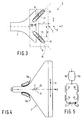
- Fig. 2 is a front elevation of the yoke ring 7 of the display tube 2 of Fig. 1, combined with the compensation coil system 3 according to the invention
- Fig. 3 is a side view.
- Two line deflection coil halves 9a and 9b (denoted by a broken line) positioned symmetrically relative to the plane of symmetry X-Z are arranged for the greater part within the yoke ring 7.
- the compensation coil system 3 comprises a first pair of core means 10 having two core portions 14 and 15 provided with compensation coils 12 and 13, and a second pair of core means 11 having two core portions 18 and 19 provided with compensation coils 16 and 17.
- the stray field (radiation field), which is generated by the line deflection coil outside the display tube, particularly on the front side of the display screen, can be compensated for by energising the compensation coil system in the correct manner.
- the pair of core means 10 extends in a plane x whose normal is transverse to the tube axis z.
- the pair of core means 11 extends in a plane ⁇ whose normal is transverse to the tube axis Z.
- the planes x and ⁇ are located equidistantly from the tube axis z.
- the core portions 14 and 15 are tilted in a given way with respect to a line passing through their centres M and being parallel to the x-z plane.
- the extent of tilt is related to the distance of this plane from the radiation centre of the deflection unit. This will be explained in greater detail with reference to Fig. 4.
- the centre C of the radiation field of the line deflection coil is located in front of the line deflection coil.
- the present invention recognizes this problem, which has led to the design of a completely novel compensation coil arrangement.
- One embodiment uses four compensation coils 12, 13, 16, 17 which are wound on rod-shaped core portions 14, 15, 18, 19 of a magnetizable material (Figs. 2, 3).
- the (axes of the) core portions 14, 15, 18, 19 extend at an angle of 90°- ⁇ to the X-Z plane.
- the rod-shaped core portions 14, 15, 18, 19 had a length of 60 mm and a diameter of 5 mm, and they were made of 4C6 ferrite.
- Rod lengths of, for example between 5 and 10 cm were found to be suitable in practice.
- the core portions 14, 15, 18, 19 are surrounded by coils 12, 13, 16, 17 having a limited number of turns (in connection with the induction) and preferably extending through the greater part of the length of the core portions.
- Permanent magnets may be arranged at opposite ends of the rod-shaped core portions for the purpose of landing error correction.
- Another possibility of reducing the influence of landing errors when using compensation coils wound on rod-shaped core portions is the addition of a configuration with two diodes.
- the compensation coil pairs are then arranged in parallel, as is shown diagrammatically in Fig. 5, in which two parallel-arranged line deflection coils 9a, 9b are connected in series with two parallel-arranged compensation coil pairs 12, 13 and 16, 17.
- Diodes 21, 22 ensure that the line deflection current is mainly passed through the "left-hand" compensation coil branch when the electron beams are deflected to the "right" on the display screen, and conversely.
- Fig. 6 is a front elevation of a yoke ring 27 with a compensation coil arrangement which is suitable for use in an alternative embodiment of a device according to the invention.
- Two line deflection coil halves 29a and 29b (denoted by a broken line) positioned symmetrically relative to the plane of symmetry X-Z are arranged for the greater part within the yoke ring 27.
- the compensation coil system comprises one pair of core means 28, 29 consisting of a magnetic core portion 23 with a compensation coil 25 and a magnetic core portion 24 with a compensation coil 26.
- the core means 28,29 extend in the y-z plane and are arranged symmetrically relative to the x-z plane. As can be seen in Fig.
- the core means 28, 29 are positioned in the y-z plane in such a way that they intersect the x-z plane at substantially the same, retrograde point P at an angle of 90 ° ⁇ .
- An advantage of the compensation coil arrangement shown in Figs. 6 and 7 is that the coils 25 and 26 can be formed in a simple manner by using lead-outs of the line deflection coil halves 37a, 37b and by winding them around the core portions 23, 24 (obliquely pointing forwards).
- the core portions 23, 24 can be positioned relative to the yoke ring 27 in such a way that they are in a magnetic flux-coupling relationship with it. As it were, one continuous core portion of great length is then formed, and the compensation requires less deflection energy than in other cases.
Landscapes
- Physics & Mathematics (AREA)
- Electromagnetism (AREA)
- Video Image Reproduction Devices For Color Tv Systems (AREA)
Claims (7)
- Bildwiedergabeanordnung mit einer Bildwiedergaberöhre, deren hinterer Teil aus einem zylinderförmigen Hals zum Aufnehmen einer Anordnung zum Erzeugen von Elektronenstrahlen besteht, und deren Vorderseite trichterförmig ist, wobei der breiteste Teil sich an der Vorderseite befindet und einen Leuchtstoffwiedergabeschirm enthält, die Wiedergabeanordnung ebenfalls eine elektromagnetische Ablenkeinheit enthält, die um einen Teil der Wiedergaberöhre zum Ablenken von Elektronenstrahlen über den Wiedergabeschirm enthält, die Einheit eine Horizontalablenkspule mit zwei Horizontalablenkspulenhälften an beiden Seiten einer Symmetrieebene und eine Vertikalablenkspule sowie ein Ausgleichsspulensystem zum Erzeugen eines magnetischen Ausgleichsfelds enthält, das dem horizontalfrequenten Strahlungsfeld in einem Raum vor dem Wiedergabeschirm entgegengesetzt gerichtet ist, das Ausgleichsspulensystem sich in der Nähe des schirmseitigen Endes der Ablenkeinheit befindet, dadurch gekennzeichnet, daß das Ausgleichsspulensystem wenigstens ein Paar von Kernmitteln enthält, wobei jedes Kernmittel des Paares einen stabförmigen magnetischen Kernteil enthält, auf dem eine Spule aufgewickelt ist und sich in einer Ebene erstreckt, deren Senkrechte quer zur Längsachse der Wiedergaberöhre verläuft, das Kernmittel symmetrisch in bezug auf die Symmetrieebene und symmetrisch in bezug auf eine Ebene angeordnet ist, die die Röhrenachse enthält, und die quer zur Symmetrieebene verläuft, wobei die Längsachsen koplanarer Kernmittel die Symmetrieebene im wesentlichen im Schnittpunkt unter einem spitzen Winkel von 90°-φ schneidet, und die Mitten der Kernmittel jedes Paares sich zwischen der Mitte der Ablenkeinheit und dem Wiedergabeschirm befinden, und der Schnittpunkt sich weiter vom Wiedergabeschirm als von den Mitten der Kernmittel befindet.
- Bildwiedergabeanordnung nach Anspruch 1,
dadurch gekennzeichnet, daß das Ausgleichsspulensystem ein Paar von Kernmitteln enthält, das sich in einer Ebene erstreckt, die die Röhrenachse enthält und quer zur Symmetrieebene der Horizontalablenkspulen verläuft. - Bildwiedergabeanordnung nach Anspruch 2,
dadurch gekennzeichnet, daß die Kernteile der Kernmittel des Paares in einem Magnetflußaustauschverhältnis mit einem Jochring aus magnetischem Material um die Horizontalablenkspule herum angeordnet ist. - Bildwiedergabeanordnung nach Anspruch 1,
dadurch gekennzeichnet, daß das Ausgleichsspulensystem ein erstes Kernmittelpaar, das sich in einer Ebene erstreckt, deren Senkrechte quer zur Röhrenachse verläuft, und ein zweites Kernmittelpaar enthält, das sich in einer zweiten Ebene erstreckt, dessen Senkrechte quer zur Röhrenachse verläuft, wobei die ersten und zweiten Ebenen äquidistant von der Röhrenachse angeordnet sind. - Bildwiedergabeanordnung nach Anspruch 1,
dadurch gekennzeichnet, daß
- Bildwiedergabeanordnung nach Anspruch 1,
dadurch gekennzeichnet, daß die Spulen dieselbe Wickelrichtung haben und im Betrieb zum Anschließen an eine Horizontalfrequenzstrahlungsquelle derart angeglichen sind, daß die Felder, die sie erzeugen, die gleiche Richtung haben. - Anordnung nach Anspruch 4, dadurch gekennzeichnet, daß eine Diodenkonfiguration mit den Spulen auf den stabförmigen Kernteilen derart elektrisch verbunden sind, daß im Betrieb hauptsächlich jene Spule erregt wird, die weitest von den abgelenkten Strahlen entfernt ist.
Applications Claiming Priority (4)
| Application Number | Priority Date | Filing Date | Title |
|---|---|---|---|
| NL8801512A NL8801512A (nl) | 1988-06-14 | 1988-06-14 | Beeldweergeefinrichting met van compensatiespoelen voorziene magnetiseerbare kernmiddelen. |
| NL8802802A NL8802802A (nl) | 1988-11-15 | 1988-11-15 | Beeldweergeefinrichting met van compensatiespoelen voorziene kernmiddelen. |
| NL8801512 | 1988-11-15 | ||
| NL8802802 | 1988-11-15 |
Publications (2)
| Publication Number | Publication Date |
|---|---|
| EP0346972A1 EP0346972A1 (de) | 1989-12-20 |
| EP0346972B1 true EP0346972B1 (de) | 1993-12-29 |
Family
ID=26646390
Family Applications (1)
| Application Number | Title | Priority Date | Filing Date |
|---|---|---|---|
| EP89201464A Expired - Lifetime EP0346972B1 (de) | 1988-06-14 | 1989-06-08 | Bildwiedergabeanordnung mit ausgleichsspulenbestückten Kernmitteln |
Country Status (6)
| Country | Link |
|---|---|
| US (1) | US5036250A (de) |
| EP (1) | EP0346972B1 (de) |
| JP (1) | JP2781207B2 (de) |
| KR (1) | KR0141699B1 (de) |
| CN (1) | CN1018224B (de) |
| DE (1) | DE68911762T2 (de) |
Families Citing this family (12)
| Publication number | Priority date | Publication date | Assignee | Title |
|---|---|---|---|---|
| KR920001582Y1 (ko) * | 1989-12-23 | 1992-03-05 | 삼성전관 주식회사 | 편향요크 |
| IT1248761B (it) * | 1990-06-08 | 1995-01-27 | Fimi Srl | Circuito di compensazione della componente orizzontale del campo magnetico terrestre per cinescopio a colori di monitor ad alta risoluzione |
| US5027819A (en) * | 1990-07-12 | 1991-07-02 | Biomagnetic Technologies, Inc. | Measurement of visually induced biomagnetic responses |
| EP0540096B1 (de) * | 1991-10-30 | 1996-01-03 | Koninklijke Philips Electronics N.V. | Ablenkjochvorrichtung mit Mitteln zur Verringerung von Leckmagnetfeldern |
| KR100243955B1 (ko) * | 1991-10-30 | 2000-02-01 | 요트.게.아. 롤페즈 | 누설자장을 감소시키는 편향 요크장치 |
| US5399939A (en) * | 1992-01-03 | 1995-03-21 | Environmental Services & Products, Inc. | Magnetic shield with cathode ray tube standoff for a computer monitor |
| US5836775A (en) * | 1993-05-13 | 1998-11-17 | Berg Tehnology, Inc. | Connector apparatus |
| JP3114787B2 (ja) * | 1994-09-30 | 2000-12-04 | 三菱自動車工業株式会社 | 排気ブレーキ装置 |
| US5959392A (en) * | 1995-01-24 | 1999-09-28 | International Business Machines Corporation | Cancellation coil arrangement for reducing stray magnetic field emissions from CRT displays |
| KR100192233B1 (ko) * | 1995-11-30 | 1999-06-15 | 구자홍 | 브라운관용 편향요크 |
| TWI252073B (en) * | 2003-08-26 | 2006-03-21 | Benq Corp | Display |
| CN112382479B (zh) * | 2020-10-21 | 2022-09-23 | 惠州市明大精密电子有限公司 | 一种工字电感及其制作方法 |
Family Cites Families (2)
| Publication number | Priority date | Publication date | Assignee | Title |
|---|---|---|---|---|
| US4853588A (en) * | 1986-09-05 | 1989-08-01 | Denki Onkyo Co., Ltd. | Deflection yoke apparatus with means for reducing unwanted radiation |
| JPH06319740A (ja) * | 1993-05-14 | 1994-11-22 | Shimadzu Corp | 超音波診断装置 |
-
1989
- 1989-05-31 US US07/359,319 patent/US5036250A/en not_active Expired - Lifetime
- 1989-06-08 DE DE68911762T patent/DE68911762T2/de not_active Expired - Fee Related
- 1989-06-08 EP EP89201464A patent/EP0346972B1/de not_active Expired - Lifetime
- 1989-06-12 CN CN89103988A patent/CN1018224B/zh not_active Expired
- 1989-06-12 KR KR1019890008046A patent/KR0141699B1/ko not_active Expired - Fee Related
- 1989-06-14 JP JP1149740A patent/JP2781207B2/ja not_active Expired - Lifetime
Also Published As
| Publication number | Publication date |
|---|---|
| JPH0233836A (ja) | 1990-02-05 |
| EP0346972A1 (de) | 1989-12-20 |
| CN1038900A (zh) | 1990-01-17 |
| CN1018224B (zh) | 1992-09-09 |
| US5036250A (en) | 1991-07-30 |
| KR900001259A (ko) | 1990-01-31 |
| DE68911762T2 (de) | 1994-07-07 |
| DE68911762D1 (de) | 1994-02-10 |
| KR0141699B1 (ko) | 1998-06-01 |
| JP2781207B2 (ja) | 1998-07-30 |
Similar Documents
| Publication | Publication Date | Title |
|---|---|---|
| EP0220777B1 (de) | Bildwiedergabeeinrichtung mit Entstörungsmitteln | |
| EP0346972B1 (de) | Bildwiedergabeanordnung mit ausgleichsspulenbestückten Kernmitteln | |
| US4992697A (en) | Picture display device with magnetizable core means comprising compensation coils | |
| EP0291121B1 (de) | Bildwiedergabevorrichtung mit Mitteln zur Kompensation der Streufelder | |
| EP0482760B1 (de) | Vorrichtung und Verfahren zur Magnetfeldunterdrückung mittels induktiven resonanten und nicht resonanten passiven Schleifen in einer Kathodenstrahlröhre | |
| US4922167A (en) | Picture display device having means for compensating line stray fields | |
| US4943753A (en) | Magnetic shunt for deflection yokes | |
| EP0281184B1 (de) | Bildwiedergabevorrichtung mit Mitteln zur Kompensation der Streufelder | |
| EP0487796B1 (de) | Kathodenstrahlröhrenanzeigeapparat | |
| EP0540096B1 (de) | Ablenkjochvorrichtung mit Mitteln zur Verringerung von Leckmagnetfeldern | |
| US5432492A (en) | Deflection yoke apparatus with auxiliar coils to compensensate magnetic leakage | |
| JPS6376245A (ja) | 偏向ヨ−ク | |
| KR920005005B1 (ko) | 음극선관 표시장치 | |
| NL8802802A (nl) | Beeldweergeefinrichting met van compensatiespoelen voorziene kernmiddelen. | |
| NL8800884A (nl) | Beeldweergeefinrichting met van compensatiespoelen voorzien magnetiseerbar kernmiddel | |
| NL8801512A (nl) | Beeldweergeefinrichting met van compensatiespoelen voorziene magnetiseerbare kernmiddelen. | |
| NL8800540A (nl) | Beeldweergeefinrichting met van compensatiespoelen voorzien kernmiddel van magnetiseerbaar materiaal. | |
| JPH10508428A (ja) | ランディング補正手段を具えるカラー表示装置 |
Legal Events
| Date | Code | Title | Description |
|---|---|---|---|
| PUAI | Public reference made under article 153(3) epc to a published international application that has entered the european phase |
Free format text: ORIGINAL CODE: 0009012 |
|
| AK | Designated contracting states |
Kind code of ref document: A1 Designated state(s): DE FR GB IT NL SE |
|
| 17P | Request for examination filed |
Effective date: 19900618 |
|
| 17Q | First examination report despatched |
Effective date: 19920703 |
|
| GRAA | (expected) grant |
Free format text: ORIGINAL CODE: 0009210 |
|
| AK | Designated contracting states |
Kind code of ref document: B1 Designated state(s): DE FR GB IT NL SE |
|
| PG25 | Lapsed in a contracting state [announced via postgrant information from national office to epo] |
Ref country code: IT Free format text: LAPSE BECAUSE OF FAILURE TO SUBMIT A TRANSLATION OF THE DESCRIPTION OR TO PAY THE FEE WITHIN THE PRE;WARNING: LAPSES OF ITALIAN PATENTS WITH EFFECTIVE DATE BEFORE 2007 MAY HAVE OCCURRED AT ANY TIME BEFORE 2007. THE CORRECT EFFECTIVE DATE MAY BE DIFFERENT FROM THE ONE RECORDED.SCRIBED TIME-LIMIT Effective date: 19931229 Ref country code: NL Effective date: 19931229 Ref country code: SE Effective date: 19931229 |
|
| REF | Corresponds to: |
Ref document number: 68911762 Country of ref document: DE Date of ref document: 19940210 |
|
| ET | Fr: translation filed | ||
| NLV1 | Nl: lapsed or annulled due to failure to fulfill the requirements of art. 29p and 29m of the patents act | ||
| PLBE | No opposition filed within time limit |
Free format text: ORIGINAL CODE: 0009261 |
|
| STAA | Information on the status of an ep patent application or granted ep patent |
Free format text: STATUS: NO OPPOSITION FILED WITHIN TIME LIMIT |
|
| 26N | No opposition filed | ||
| REG | Reference to a national code |
Ref country code: FR Ref legal event code: CD |
|
| REG | Reference to a national code |
Ref country code: FR Ref legal event code: CD |
|
| PGFP | Annual fee paid to national office [announced via postgrant information from national office to epo] |
Ref country code: GB Payment date: 19990621 Year of fee payment: 11 |
|
| PGFP | Annual fee paid to national office [announced via postgrant information from national office to epo] |
Ref country code: FR Payment date: 19990628 Year of fee payment: 11 |
|
| PGFP | Annual fee paid to national office [announced via postgrant information from national office to epo] |
Ref country code: DE Payment date: 19990722 Year of fee payment: 11 |
|
| PG25 | Lapsed in a contracting state [announced via postgrant information from national office to epo] |
Ref country code: GB Free format text: LAPSE BECAUSE OF NON-PAYMENT OF DUE FEES Effective date: 20000608 |
|
| GBPC | Gb: european patent ceased through non-payment of renewal fee |
Effective date: 20000608 |
|
| PG25 | Lapsed in a contracting state [announced via postgrant information from national office to epo] |
Ref country code: FR Free format text: LAPSE BECAUSE OF NON-PAYMENT OF DUE FEES Effective date: 20010228 |
|
| REG | Reference to a national code |
Ref country code: FR Ref legal event code: ST |
|
| PG25 | Lapsed in a contracting state [announced via postgrant information from national office to epo] |
Ref country code: DE Free format text: LAPSE BECAUSE OF NON-PAYMENT OF DUE FEES Effective date: 20010403 |