EP0446461A2 - Halogen incandescent lamp having a single pinch - Google Patents
Halogen incandescent lamp having a single pinch Download PDFInfo
- Publication number
- EP0446461A2 EP0446461A2 EP90124461A EP90124461A EP0446461A2 EP 0446461 A2 EP0446461 A2 EP 0446461A2 EP 90124461 A EP90124461 A EP 90124461A EP 90124461 A EP90124461 A EP 90124461A EP 0446461 A2 EP0446461 A2 EP 0446461A2
- Authority
- EP
- European Patent Office
- Prior art keywords
- bulb
- halogen incandescent
- incandescent lamp
- luminous element
- web
- Prior art date
- Legal status (The legal status is an assumption and is not a legal conclusion. Google has not performed a legal analysis and makes no representation as to the accuracy of the status listed.)
- Granted
Links
- 229910052736 halogen Inorganic materials 0.000 title claims description 22
- 150000002367 halogens Chemical class 0.000 title claims description 22
- 239000011521 glass Substances 0.000 claims abstract description 22
- 239000000463 material Substances 0.000 claims abstract description 6
- 241000283216 Phocidae Species 0.000 description 8
- VYPSYNLAJGMNEJ-UHFFFAOYSA-N Silicium dioxide Chemical compound O=[Si]=O VYPSYNLAJGMNEJ-UHFFFAOYSA-N 0.000 description 3
- ZOKXTWBITQBERF-UHFFFAOYSA-N Molybdenum Chemical compound [Mo] ZOKXTWBITQBERF-UHFFFAOYSA-N 0.000 description 2
- 238000010891 electric arc Methods 0.000 description 2
- 230000002349 favourable effect Effects 0.000 description 2
- 239000011888 foil Substances 0.000 description 2
- 238000000034 method Methods 0.000 description 2
- 229910052750 molybdenum Inorganic materials 0.000 description 2
- 239000011733 molybdenum Substances 0.000 description 2
- 241001188564 Gymnosoma par Species 0.000 description 1
- 238000005452 bending Methods 0.000 description 1
- 239000000919 ceramic Substances 0.000 description 1
- 238000010276 construction Methods 0.000 description 1
- 238000004031 devitrification Methods 0.000 description 1
- 238000005516 engineering process Methods 0.000 description 1
- 238000005429 filling process Methods 0.000 description 1
- 150000002366 halogen compounds Chemical class 0.000 description 1
- 230000017525 heat dissipation Effects 0.000 description 1
- 239000011261 inert gas Substances 0.000 description 1
- 238000004519 manufacturing process Methods 0.000 description 1
- 230000035945 sensitivity Effects 0.000 description 1
- 230000035939 shock Effects 0.000 description 1
- 238000003892 spreading Methods 0.000 description 1
- 239000005341 toughened glass Substances 0.000 description 1
- 230000007704 transition Effects 0.000 description 1
- WFKWXMTUELFFGS-UHFFFAOYSA-N tungsten Chemical compound [W] WFKWXMTUELFFGS-UHFFFAOYSA-N 0.000 description 1
Images


Classifications
-
- H—ELECTRICITY
- H01—ELECTRIC ELEMENTS
- H01K—ELECTRIC INCANDESCENT LAMPS
- H01K1/00—Details
- H01K1/18—Mountings or supports for the incandescent body
Definitions
- the invention relates to a halogen incandescent lamp pinched on one side according to the preamble of claim 1.
- Such a halogen incandescent lamp is known from DE-GM 87 16 797.
- the axial filament is held by a frame that is formed by the two power supplies.
- a support wire is also provided, which is attached approximately in the middle of the filament.
- the structure of the frame is greatly simplified by the arrangement according to the invention.
- the support wire is replaced by a glass web, which is formed from the material of the bulb and into which a section of the filament is squeezed.
- the crossbar can be saved and thus the overall height of the lamp can be reduced.
- the good fixation of the filament also improves the shock resistance of the lamp. This also considerably reduces the spiral sag, which can lead to contact with the inner wall of the piston.
- the invention is preferably suitable for halogen incandescent lamps which are directly connected to the mains voltage.
- the conditions are particularly favorable for mains voltages of approx. 110 - 120 V or less, since then the length and rigidity of the filament reach the most favorable values.
- a single glass web is then sufficient, which fixes the luminous element approximately in the middle.
- mains voltages e.g. 230 V
- the luminous element is advantageously subdivided into luminous sections which are double-helixed and connecting sections which are single-helixed. Under certain circumstances, simply coiled filament sections and uncoiled sections as connecting sections can also be used as luminous sections.
- the connecting sections advantageously have a reduced power density compared to the luminous sections.
- connection section can advantageously have a core pin in the region of the glass web.
- the webs are only produced after being squeezed, but before filling.
- the lamp bulb is heated in the area of the future webs with burners and shaped by means of stamps, which are opposite each other.
- This technology has the great advantage that the position of the luminous element can no longer be subsequently adjusted by this process, even in the case of frames without a crossbar.
- the webs can be produced particularly easily by deep-drawing two "glass fingers” using two rod-shaped stamps, a stopper being left in the lamp axis when the two "glass fingers” touch.
- halogen incandescent lamp with a long service life (2000 hours) for general lighting is presented, which is extremely shockproof and suitable for a simple construction with few components (without crossbars).
- the pipe diameter can be reduced by approx. 2-4 mm and the overall length by approx. 7 mm, so that additional savings in filling quantities occur due to the smaller piston volume.
- this lamp Due to the small size of this lamp, it is ideal for use in an outer bulb. Possibly. it can be equipped with a reflector which has, for example, a parabolic contour (so-called halogen PAR lamp).
- the lamp according to the invention is suitable for direct operation at mains voltage, which should be understood to mean a range from approximately 80 V to 250 V. Typical wattages are 15 to 500 W.
- mains voltage which should be understood to mean a range from approximately 80 V to 250 V. Typical wattages are 15 to 500 W.
- the lamp can be surrounded with an outer bulb. Due to its compactness, this lamp can also be used advantageously in reflectors (e.g. PAR lamps, cold light reflector lamps) and optionally equipped with screw or pin bases.
- Quartz glass is preferred as the piston material, since this material can best withstand the high temperatures and the stresses occurring on the glass web. Tempered glass can also be used for lamps with low power consumption.
- the mounting of the filament can be further improved in that the current supply leading to the distal end of the filament in a plane, which includes the filament, has a hairpin-shaped section that runs along the lamp axis is arranged. Each leg of this section opens into a slope facing the piston wall.
- the curved section is suitable as a holder for a - preferably double - coiled end section of the filament. While in previous holders of this type only one arm of the power supply could be used to hold the luminous element, so that only half-hearted measures such as a simple bending of the frame arm or a flattening could be considered for a non-slip fit (cf. e.g. again DE-GM 87 16 797 or also US Pat. No.
- a further simplification of the frame structure can be achieved in that the power supply, which connects the near-pinch end of the filament with the associated film, is formed by a simply coiled end section of the filament.
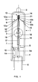
- Figures 1 and 2 show schematically different side views of a 120 V halogen incandescent lamp 1 with a power of 90 W. It has a cylindrical bulb 2 made of quartz glass with a total length of 40 mm, which at one end, which is rounded, with a pump tip 3 one or more halogen compounds and was filled with inert gas. The other end of the piston 2 is provided with a pinch seal 4, to which, for example, a ceramic base (not shown) can be attached. Two molybdenum foils 5a, 5b are melted asymmetrically into the pinch seal 4 and connect the two outer power supply lines 6 with two inner power supply lines 7, 8 in an electrically conductive and vacuum-tight manner.
- the first inner power supply 7 (made of tungsten wire) is guided along the inner wall 9 of the piston to the end of the piston which is distant from the pinch. Its pinch-side end 10 is from the inner wall 9 to the film 5a, which is arranged on the edge of the pinch seal, bent away, while its pinch-distant end 11 forms a first bevel 12a, which is bent against the inner wall 9 by about 60 ° to the lamp axis. Shortly before reaching the lamp axis, one leg 13a of a hairpin-shaped section 13 aligned parallel to the lamp axis is attached to it. The bend 14 of the section 13 is directed towards the pump tip 3; however, it is clearly spaced from it.
- the free end of the power supply is designed as a second leg 13b and second bevel 12b in mirror image of the first leg 13a and the first slope 12a.
- the second slope 12b ends at the opposite piston inner wall 9 'and is bent into a short extension 15 which points along the piston inner wall 9' in the direction of the pinch seal 4.
- the inner power supply 7 is resiliently clamped between two diametrically opposite points on the inner wall of the bulb and automatically centers a luminous element 16 in the lamp axis.
- the luminous element 16 is equipped with two double-coiled luminous sections 17 and is stretched axially in the bulb between the second film 5b and the hairpin-shaped section 13.
- the two double coiled sections 17 are spaced apart from one another by a single coiled connecting section 18.
- An also simply coiled end section of the filament takes over the function of the second inner power supply 8 and extends in a straight line from the lit section 17 near the pinch to the second film 5b, which is symmetrical is arranged to the lamp axis in the middle of the pinch seal.
- the luminous element 16 is fixed in the middle of the connecting section 18 by a glass web 19 which extends transversely to the lamp axis and to the plane which contains the luminous element 16 and the first power supply 7.
- the glass web 19 is designed as a tube which extends approximately in the middle of the bulb over the inner diameter of the bulb.
- the tube has an inner diameter of approx. 1-2 mm near the axis and widens towards the piston wall on both sides in the manner of a funnel to about twice to four times the diameter.
- the tube has a circular cross section.
- an elongated or oval cross section near the axis is particularly advantageous (as shown in FIGS. 1 and 2), since this facilitates the fixation of the luminous element.
- the longer axis of the tube is aligned transversely to the lamp axis and to the filament.
- the ratio between the longer axis and the shorter axis of the tube is approximately 2: 1.
- the filament is squeezed into the glass web 19 so that a type of plug 20 is left in the tube near the axis.
- the glass web 19 takes over the function of a frame part.
- Another frame part is formed by the first inner power supply 7, which holds the end of the luminous element that is distant from the pinch.
- the non-crushing, double-coiled luminous section 17 of the luminous element is connected to a double-coiled, short end section 21 via a short connecting section 18 '.
- This end section 21 is drawn onto the hairpin-shaped section 13 of the power supply.
- the two spread legs 12 secure the end portion 21 against slipping out.
- the same features are provided with the same reference numbers.
- the luminous element 16 which is longer due to the higher voltage, has three luminous sections 22 which are spaced apart by two connecting sections 23. Each connecting section 23 is fixed by a glass web 24.
- the halogen incandescent lamp 1 is mounted in an outer bulb 25 with a screw base, which has a parabolic reflector 26 (halogen PAR lamps).
- the two outer power supply lines 6 are squeezed in a plate base 27 and connected to the screw base 28 in a manner known per se.
- the plate foot 27 is melted into the neck 29 of the evacuated outer bulb 25.
- the invention is not restricted to the exemplary embodiments shown.
- the two Molybdenum foils one of which is arranged laterally on the edge of the pinch seal and one in the middle, have different widths, or the centrally arranged film can be melted transversely into the pinch seal.
- This also simplifies the frame structure, since there is no need to bend the shorter of the two power leads out of the lamp axis.
- this is in turn the prerequisite for the fact that the simply coiled end section of the filament can be used as the power supply.
- the cylindrical glass bulb has a circular cross section.
- an elongated cross section e.g. elliptical
- the glass webs extending in the direction of the shorter axis to ensure a certain minimum thickness of the glass webs.
Landscapes
- Non-Portable Lighting Devices Or Systems Thereof (AREA)
- Vessels And Coating Films For Discharge Lamps (AREA)
Abstract
Der Kolben (2) der Lampe weist mindestens einen rohrartigen Glassteg (19) auf, der aus dem Material des Kolbens gebildet ist und der den axial ausgerichteten Leuchtkörper (16) punktuell fixiert, indem der Steg sich quer zum Leuchtkörper (16) zwischen gegenüberliegenden Punkten der Kolbenwand erstreckt, wobei der Leuchtkörper (16) im Steg (19) eingequetscht ist. <IMAGE>The bulb (2) of the lamp has at least one tubular glass web (19) which is formed from the material of the bulb and which fixes the axially aligned luminous element (16) at certain points by the crosspiece extending transversely to the luminous element (16) between opposite points the bulb wall extends, the luminous element (16) being squeezed into the web (19). <IMAGE>
Description
Die Erfindung betrifft eine einseitig gequetschte Halogen-Glühlampe nach dem Oberbegriff des Anspruchs 1.The invention relates to a halogen incandescent lamp pinched on one side according to the preamble of
Eine derartige Halogenglühlampe ist aus dem DE-GM 87 16 797 bekannt. Bei dieser Lampe ist der axiale Leuchtkörper von einem Gestell gehaltert, das von den zwei Stromzuführungen gebildet wird. Zusätzlich ist außerdem ein Stützdraht vorgesehen, der etwa in der Mitte des Leuchtkörpers befestigt ist. Diese drei Gestellteile sind zusammen in einem Querbalken aus Quarzglas fixiert. Eine derartige Lampe weist eine relativ große Baulänge auf und ihre Herstellung ist relativ aufwendig und teuer, da viele Einzelteile benötigt werden und zusammengesetzt werden müssen.Such a halogen incandescent lamp is known from DE-GM 87 16 797. In this lamp, the axial filament is held by a frame that is formed by the two power supplies. In addition, a support wire is also provided, which is attached approximately in the middle of the filament. These three frame parts are fixed together in a crossbeam made of quartz glass. Such a lamp has a relatively large overall length and its production is relatively complex and expensive, since many individual parts are required and have to be assembled.
Es ist Aufgabe der Erfindung, eine Halogenglühlampe mit Axialwendel bereitzustellen, die sich besonders einfach und kostensparend herstellen läßt und eine geringe Erschütterungsempfindlichkeit aufweist.It is an object of the invention to provide a halogen incandescent lamp with an axial filament, which can be produced in a particularly simple and cost-saving manner and which has a low sensitivity to vibrations.
Diese Aufgabe der Erfindung wird durch die kennzeichnenden Merkmale des Anspruchs 1 gelöst. Besonders vorteilhafte Ausführungen finden sich in den Unteransprüchen.This object of the invention is achieved by the characterizing features of
Der Gestellaufbau wird durch die erfindungsgemäße Anordnung stark vereinfacht. Der Stützdraht ist ersetzt durch einen Glassteg, der aus dem Material des Kolbens gebildet ist und in den ein Abschnitt des Leuchtkörpers eingequetscht ist.The structure of the frame is greatly simplified by the arrangement according to the invention. The support wire is replaced by a glass web, which is formed from the material of the bulb and into which a section of the filament is squeezed.
Weiterhin kann der Querbalken eingespart werden und somit die Bauhöhe der Lampe veringert werden. Die gute Fixierung des Leuchtkörpers verbessert außerdem die Stoßfestigkeit der Lampe. Auch der Wendeldurchhang, der bis zum Berühren der Kolbeninnenwand führen kann, ist dadurch erheblich vermindert.Furthermore, the crossbar can be saved and thus the overall height of the lamp can be reduced. The good fixation of the filament also improves the shock resistance of the lamp. This also considerably reduces the spiral sag, which can lead to contact with the inner wall of the piston.
Die Erfindung eignet sich bevorzugt für Halogenglühlampen, die direkt an Netzspannung anliegen. Besonders günstig gestalten sich die Verhältnisse bei Netzspannungen von ca. 110 - 120 V oder weniger, da dann die Länge und Steifigkeit des Leuchtkörpers die günstigsten Werte erreicht. Im allgemeinen genügt dann ein einziger Glassteg, der den Leuchtkörper etwa in seiner Mitte fixiert. Für höhere Netzspannungen (z.B. 230 V) empfiehlt es sich, mehrere Glasstege zu verwenden.The invention is preferably suitable for halogen incandescent lamps which are directly connected to the mains voltage. The conditions are particularly favorable for mains voltages of approx. 110 - 120 V or less, since then the length and rigidity of the filament reach the most favorable values. In general, a single glass web is then sufficient, which fixes the luminous element approximately in the middle. For higher mains voltages (e.g. 230 V) it is advisable to use several glass bars.
Der Leuchtkörper ist vorteilhaft in leuchtende Abschnitte, die doppelt gewendelt sind, und Verbindungsabschnitte, die einfach gewendelt sind, unterteilt. Als leuchtende Abschnitte können unter Umständen auch einfach gewendelte und als Verbindungsabschnitte ungewendelte Leuchtkörperabschnitte verwendet werden.The luminous element is advantageously subdivided into luminous sections which are double-helixed and connecting sections which are single-helixed. Under certain circumstances, simply coiled filament sections and uncoiled sections as connecting sections can also be used as luminous sections.
Das Schwärzungsproblem spielt bei den hier vorgestellten Glasstegen keine Rolle, weil sie aus dem Material des Kolbens gebildet sind. Zudem weisen die Verbindungsabschnitte vorteilhaft eine verringerte Leistungsdichte im Vergleich zu den leuchtenden Abschnitten auf.The problem of blackening plays no role in the glass webs presented here because they are formed from the material of the bulb. In addition, the connecting sections advantageously have a reduced power density compared to the luminous sections.
Durch das Einquetschen der Verbindungsabschnitte in die Glasstege entsteht ein inniger Kontakt, der eine hervorragende Wärmeableitung nach außen bewirkt. Durch die dadurch gegebene erheblich geringere Temperaturbelastung der Glasstege werden Schwärzungen und Entglasungserscheinungen verhindert. Vorteilhaft kann in diesem Zusammenhang der Verbindungsabschnitt im Bereich des Glassteges einen Kernstift aufweisen.Squeezing the connecting sections into the glass webs creates an intimate contact that causes excellent heat dissipation to the outside. The resulting considerably lower temperature load on the glass webs prevents blackening and devitrification phenomena. In this context, the connection section can advantageously have a core pin in the region of the glass web.
Dadurch, daß die Stege trichterförmig ausgebildet sind, treten keine zu dünnen Stellen - die den Berstdruck mindern könnten - im Bereich des Übergangs zur Kolbenwand auf und die Wanddicke bleibt ziemlich homogen.Due to the fact that the webs are funnel-shaped, there are no places that are too thin - which could reduce the burst pressure - in the region of the transition to the piston wall and the wall thickness remains fairly homogeneous.
Die Herstellung der Stege erfolgt erst nach dem Quetschen, jedoch vor dem Füllen. Der Lampenkolben wird im Bereich der zukünftigen Stege mit Brennern erhitzt und mittels Stempel geformt, die jeweils einander gegenüberliegen. Diese Technik hat den großen Vorteil, daß die Lage des Leuchtkörpers auch bei Gestellen ohne Querbalken durch diesen Vorgang nicht mehr nachträglich dejustiert werden kann. Die Stege lassen sich besonders einfach herstellen durch Tiefziehen zweier "Glasfinger" mittels zweier stabförmiger Stempel, wobei ein Stopfen in der Lampenachse stehengelassen wird, wenn sich die beiden "Glasfinger" berühren.The webs are only produced after being squeezed, but before filling. The lamp bulb is heated in the area of the future webs with burners and shaped by means of stamps, which are opposite each other. This technology has the great advantage that the position of the luminous element can no longer be subsequently adjusted by this process, even in the case of frames without a crossbar. The webs can be produced particularly easily by deep-drawing two "glass fingers" using two rod-shaped stamps, a stopper being left in the lamp axis when the two "glass fingers" touch.
Insgesamt wird somit eine Halogenglühlampe mit langer Lebensdauer (2000 Std.) für die Allgemeinbeleuchtung vorgestellt, die extrem stoßfest ist und sich für eine einfache Konstruktion mit wenig Bauteilen (ohne Querbalken) eignet. Im Vergleich zu standardisierten Halogenglühlampen kann der Rohrdurchmesser um ca. 2-4 mm und die Baulänge um ca. 7 mm verkleinert werden, so daß aufgrund des kleineren Kolbenvolumes noch zusätzliche Einsparungen bei den Füllmengen auftreten.Overall, a halogen incandescent lamp with a long service life (2000 hours) for general lighting is presented, which is extremely shockproof and suitable for a simple construction with few components (without crossbars). Compared to standardized halogen light bulbs the pipe diameter can be reduced by approx. 2-4 mm and the overall length by approx. 7 mm, so that additional savings in filling quantities occur due to the smaller piston volume.
Aufgrund der Kleinheit dieser Lampe eignet sie sich vorzüglich zur Verwendung in einem Außenkolben. Ggf. kann dieser mit einem Reflektor ausgestattet sein, der beispielsweise eine parabolische Kontur besitzt (sog. Halogen-PAR-Lampe).Due to the small size of this lamp, it is ideal for use in an outer bulb. Possibly. it can be equipped with a reflector which has, for example, a parabolic contour (so-called halogen PAR lamp).
Die Lampe gemäß der Erfindung eignet sich für den direkten Betrieb an Netzspannung, worunter ein Bereich von ca. 80 V bis 250 V verstanden werden soll. Typische Wattstufen sind 15 bis 500 W. Für Allgemeinbeleuchtungszwecke kann die Lampe mit einem Außenkolben umgeben werden. Aufgrund ihrer Kompaktheit kann diese Lampe aber auch vorteilhaft in Reflektoren (z.B. PAR-Lampen, Kaltlichtreflektorlampen) eingesetzt werden und wahlweise mit Schraub- oder Stiftsockeln bestückt werden.The lamp according to the invention is suitable for direct operation at mains voltage, which should be understood to mean a range from approximately 80 V to 250 V. Typical wattages are 15 to 500 W. For general lighting purposes, the lamp can be surrounded with an outer bulb. Due to its compactness, this lamp can also be used advantageously in reflectors (e.g. PAR lamps, cold light reflector lamps) and optionally equipped with screw or pin bases.
Als Kolbenmaterial eignet sich bevorzugt Quarzglas, da dieses Material den hohen Temperaturen und den am Glassteg auftretenden Spannungen am besten widerstehen kann. Für Lampen mit geringer Leistungsaufnahme kann auch Hartglas verwendet werden.Quartz glass is preferred as the piston material, since this material can best withstand the high temperatures and the stresses occurring on the glass web. Tempered glass can also be used for lamps with low power consumption.
Die Halterung des Leuchtkörpers kann weiter verbessert werden, indem die zum quetschungsfernen Ende des Leuchtkörpers führende Stromzuführung in einer Ebene, die den Leuchtkörper einschließt, einen haarnadelförmig gebogenen Abschnitt aufweist, der entlang der Lampenachse angeordnet ist. Jeder Schenkel dieses Abschnitts mündet in eine zur Kolbenwand gerichtete Schräge. Der gebogene Abschnitt eignet sich als Halter für einen - vorzugsweise doppelt - gewendelten Endabschnitt des Leuchtkörpers. Während bei bisherigen Halterungen dieser Art nur ein Arm der Stromzuführung für die Halterung des Leuchtkörpers verwendet werden konnte, so daß für einen rutschfesten Sitz lediglich halbherzige Maßnahmen wie eine einfache Biegung des Gestellarms oder eine Anflachung in Frage kamen (vgl. z.B. wieder DE-GM 87 16 797 oder auch US-PS 3 840 953), wird jetzt ein verbesserter Sitz durch die Spreizung der beiden Schrägen an den Enden der beiden Schenkel des haarnadelförmigen Abschnitts erzielt. Zusätzlich wird auf diese Weise eine exakte Zentrierung des Leuchtkörpers erreicht, da die beiden Schrägen sich symmetrisch zwischen gegenüberliegenden Punkten der Kolbeninnenwand erstrecken. Der Winkel, den die Schrägen in bezug auf die Lampenachse bilden, kann hierbei zwischen 10° und 80° liegen. Weiterhin wird eine Behinderung des Füllvorgangs vermieden, weil das Gestell nicht in der Pumpspitze befestigt werden muß. Diese Haltetechnik kann im Prinzip auch ohne die gleichzeitige Anwendung der Glasstege eingesetzt werden, ist in Verbindung damit jedoch besonders vorteilhaft.The mounting of the filament can be further improved in that the current supply leading to the distal end of the filament in a plane, which includes the filament, has a hairpin-shaped section that runs along the lamp axis is arranged. Each leg of this section opens into a slope facing the piston wall. The curved section is suitable as a holder for a - preferably double - coiled end section of the filament. While in previous holders of this type only one arm of the power supply could be used to hold the luminous element, so that only half-hearted measures such as a simple bending of the frame arm or a flattening could be considered for a non-slip fit (cf. e.g. again DE-GM 87 16 797 or also US Pat. No. 3,840,953), an improved fit is now achieved by the spreading of the two bevels at the ends of the two legs of the hairpin-shaped section. In addition, an exact centering of the luminous element is achieved in this way, since the two bevels extend symmetrically between opposite points of the inner wall of the bulb. The angle that the bevels form with respect to the lamp axis can be between 10 ° and 80 °. Furthermore, a hindrance to the filling process is avoided because the frame does not have to be fixed in the pump tip. In principle, this holding technique can also be used without the simultaneous use of the glass webs, but is particularly advantageous in connection with it.
Eine weitere Vereinfachung des Gestellaufbaus kann dadurch erzielt werden, daß die Stromzuführung, die das quetschungsnahe Ende des Leuchtkörpers mit der zugehörigen Folie verbindet, durch einen einfach gewendelten Endabschnitt des Leuchtkörpers gebildet wird.A further simplification of the frame structure can be achieved in that the power supply, which connects the near-pinch end of the filament with the associated film, is formed by a simply coiled end section of the filament.
Mehrere Ausführungsbeispiele der Erfindung werden in folgenden anhand von Zeichnungen näher beschrieben. Es zeigen:
Figur 1- ein erstes Ausführungsbeispiel einer Halogenglühlampe in Seitenansicht
Figur 2- dieselbe Halogenglühlampe in um 90° gedrehter Seitenansicht
Figur 3- ein zweites Ausführungsbeispiel in Seitenansicht
Figur 4- ein weiteres Ausführungsbeispiel mit Außenkolben.
- Figure 1
- a first embodiment of a halogen lamp in side view
- Figure 2
- the same halogen bulb in a side view rotated by 90 °
- Figure 3
- a second embodiment in side view
- Figure 4
- another embodiment with outer bulb.
Figur 1 und 2 zeigen schematisch verschiedene Seitenansichten einer 120 V-Halogenglühlampe 1 mit einer Leistung von 90 W. Sie besitzt einen zylindrischen Kolben 2 aus Quarzglas mit einer Gesamtlänge von 40 mm, der an einem Ende, das abgerundet ist, über eine Pumpspitze 3 mit einer oder mehreren Halogenverbindungen und mit Inertgas gefüllt wurde. Das andere Ende des Kolbens 2 ist mit einer Quetschdichtung 4 versehen, an der z.B. ein Sockel aus Keramik (nicht gezeigt) befestigt werden kann. In die Quetschdichtung 4 sind zwei Molybdänfolien 5a, 5b asymmetrisch eingeschmolzen, die zwei äußere Stromzuführungen 6 mit zwei inneren Stromzuführungen 7,8 elektrisch leitend und vakuumdicht verbinden. Die erste innere Stromzuführung 7 (aus Wolframdraht) ist entlang der Kolbeninnenwand 9 zum quetschungsfernen Ende des Kolbens geführt. Ihr quetschungsseitiges Ende 10 ist von der Innenwand 9 zur Folie 5a, die am Rande der Quetschdichtung angeordnet ist, weggebogen, während ihr quetschungsfernes Ende 11 eine erste Schräge 12a bildet, die gegen die Innenwand 9 um etwa 60° zur Lampenachse hin abgebogen ist. Kurz vor Erreichen der Lampenachse ist daran der eine Schenkel 13a eines parallel zur Lampenachse ausgerichteten haarnadelförmigen Abschnitts 13 angesetzt. Die Biegung 14 des Abschnitts 13 ist zur Pumpspitze 3 hin gerichtet; sie ist davon jedoch deutlich beabstandet. In bezug auf die Lampenachse ist spiegelbildlich zum ersten Schenkel 13a und der ersten Schräge 12a das freie Ende der Stromzuführung als zweiter Schenkel 13b und zweite Schräge 12b ausgeführt. Die zweite Schräge 12b endet an der gegenüberliegenden Kolbeninnenwand 9' und ist zu einem kurzen Fortsatz 15, der entlang der Kolbeninnenwand 9' in Richtung Quetschdichtung 4 zeigt, abgebogen. Auf diese Weise ist die innere Stromzuführung 7 federnd zwischen zwei diametral gegenüberliegenden Punkten der Kolbeninnenwand eingespannt und zentriert einen Leuchtkörper 16 automatisch in der Lampenachse.Figures 1 and 2 show schematically different side views of a 120 V halogen
Der Leuchtkörper 16 ist mit zwei doppelt gewendelten leuchtenden Abschnitten 17 ausgestattet und ist axial im Kolben zwischen der zweiten Folie 5b und dem haarnadelförmigen Abschnitt 13 aufgespannt. Die beiden doppelt gewendelten Abschnitte 17 sind durch einen einfach gewendelten Verbindungsabschnitt 18 voneinander beabstandet. Ein ebenfalls einfach gewendelter Endabschnitt des Leuchtkörpers übernimmt die Funktion der zweiten inneren Stromzuführung 8 und erstreckt sich geradlinig vom quetschungsnahen leuchtenden Abschnitt 17 bis zur zweiten Folie 5b, die symmetrisch zur Lampenachse in der Mitte der Quetschdichtung angeordnet ist. Der Lampenaufbau wird dadurch nicht nur vereinfacht (Einsparung einer seperaten Stromzuführung), sondern es wird auch eine zusätzliche Sicherungsfunktion gewonnen, da der Teil des Endabschnitts, der in die Quetschdichtung eingeschmolzen ist, einen Kanal freiläßt, so daß bei Ausbildung einer Bogenentladung das Gewendel verpufft, wodurch die Bogenentladung gelöscht wird.The
In der Mitte des Verbindungsabschnitts 18 wird der Leuchtkörper 16 durch einen Glassteg 19 fixiert, der sich quer zur Lampenachse und zur Ebene, die den Leuchtkörper 16 und die erste Stromzuführung 7 enthält, erstreckt. Der Glassteg 19 ist als Rohr ausgebildet, das sich etwa in der Mitte des Kolbens über den Innendurchmesser des Kolbens erstreckt. Das Rohr hat in Achsnähe einen Innendurchmesser von ca. 1-2 mm und weitet sich zur Kolbenwand hin auf beiden Seiten nach Art eines Trichters etwa auf den doppelten bis vierfachen Durchmesser auf.The
Im einfachsten Fall hat das Rohr einen kreisförmigen Querschnitt. Besonders vorteilhaft ist jedoch (wie in Fig. 1 und 2 dargestellt) ein langgestreckter oder ovaler Querschnitt in Achsnähe, da dies die Fixierung des Leuchtkörpers erleichtert. Die längere Achse des Rohres ist dabei quer zur Lampenachse und zum Leuchtkörper ausgerichtet. Das Verhältnis zwischen längerer Achse und kürzerer Achse des Rohres beträgt etwa 2:1. Der Leuchtkörper ist in den Glassteg 19 eingequetscht, so daß in Achsnähe eine Art Stopfen 20 im Rohr belassen ist.In the simplest case, the tube has a circular cross section. However, an elongated or oval cross section near the axis is particularly advantageous (as shown in FIGS. 1 and 2), since this facilitates the fixation of the luminous element. The longer axis of the tube is aligned transversely to the lamp axis and to the filament. The ratio between the longer axis and the shorter axis of the tube is approximately 2: 1. The filament is squeezed into the
Der Glassteg 19 übernimmt die Funktion eines Gestellteils. Ein weiteres Gestellteil wird durch die erste innere Stromzuführung 7 gebildet, die das quetschungsferne Ende des Leuchtkörpers haltert. Zu diesem Zweck ist der quetschungsferne, doppelt gewendelte leuchtende Abschnitt 17 des Leuchtkörpers über einen kurzen Verbindungsabschnitt 18' mit einem doppelt gewendelten, kurzen Endabschnitt 21 verbunden. Dieser Endabschnitt 21 ist auf den haarnadelförmig gebogenen Abschnitt 13 der Stromzuführung aufgezogen. Die beiden gespreizten Schenkel 12 sichern den Endabschnitt 21 gegen ein Herausrutschen.The
Bei einem weiteren Ausführungsbeispiel (Fig. 3) einer Lampe für den Betrieb an 230 V sind gleiche Merkmale mit gleichen Bezugsziffern versehen.
Der Leuchtkörper 16, der wegen der höheren Spannung länger ist, weist jedoch drei leuchtende Abschnitte 22 auf, die durch zwei Verbindungsabschnitte 23 beabstandet sind. Jeder Verbindungsabschnitt 23 ist durch einen Glassteg 24 fixiert.In a further exemplary embodiment (FIG. 3) of a lamp for operation at 230 V, the same features are provided with the same reference numbers.
However, the
In einem weiteren Ausführungsbeispiel (Fig. 4) ist die Halogenglühlampe 1 in einem Außenkolben 25 mit Schraubsockel montiert, der einen parabolischen Reflektor 26 aufweist (Halogen-PAR-Lampen). Die beiden äußeren Stromzuführungen 6 sind in einem Tellerfuß 27 eingequetscht und mit dem Schraubsockel 28 in an sich bekannter Weise verbunden. Der Tellerfuß 27 ist im Hals 29 des evakuierten Außenkolbens 25 eingeschmolzen.In a further exemplary embodiment (FIG. 4), the halogen
Die Erfindung ist nicht auf die gezeigten Ausführungsbeispiele beschränkt. Insbesondere können die beiden Molybdänfolien, von denen eine seitlich am Rand der Quetschdichtung und eine mittig angeordnet ist, unterschiedliche Breiten besitzen, oder die mittig angeordnete Folie kann querliegend in die Quetschdichtung eingeschmolzen sein. Auch dadurch wird der Gestellaufbau vereinfacht, da die Notwendigkeit, die kürzere der beiden Stromzuführung aus der Lampenachse zu biegen, entfällt. Dies ist jedoch wiederum die Voraussetzung dafür, daß als Stromzuführung der einfach gewendelte Endabschnitt des Leuchtkörpers verwendet werden kann.The invention is not restricted to the exemplary embodiments shown. In particular, the two Molybdenum foils, one of which is arranged laterally on the edge of the pinch seal and one in the middle, have different widths, or the centrally arranged film can be melted transversely into the pinch seal. This also simplifies the frame structure, since there is no need to bend the shorter of the two power leads out of the lamp axis. However, this is in turn the prerequisite for the fact that the simply coiled end section of the filament can be used as the power supply.
Der zylindrische Glaskolben weist im einfachsten Fall einen kreisförmigen Querschnitt auf. Mit zunehmender Größe des Kolbens kann ein länglicher Querschnitt (z.B. elliptisch) Vorteile bringen, wobei die Glasstege sich in Richtung der kürzeren Achse erstrecken um eine bestimmte Mindestdicke der Glasstege zu gewährleisten.In the simplest case, the cylindrical glass bulb has a circular cross section. As the size of the piston increases, an elongated cross section (e.g. elliptical) can bring advantages, with the glass webs extending in the direction of the shorter axis to ensure a certain minimum thickness of the glass webs.
Claims (9)
dadurch gekennzeichnet, daß mindestens ein rohrartiger Glassteg (19), der aus dem Material des Kolbens gebildet ist, den Leuchtkörper (16) punktuell fixiert, indem der Steg (19) sich quer zum Leuchtkörper (16) zwischen diametral gegenüberliegenden Punkten der Kolbeninnenwand erstreckt, wobei der Leuchtkörper (16) im Steg (19) eingequetscht ist.Halogen incandescent lamp (1) squeezed on one side with a cylindrical glass bulb (2) which defines a lamp axis and an axially aligned lamp body (16) which is held by a frame which contains a power supply (7) which runs along the inside wall of the bulb (9) is led to the end of the filament away from the pinch,
characterized in that at least one tubular glass web (19), which is formed from the material of the bulb, fixes the luminous element (16) at certain points, in that the web (19) extends transversely to the luminous element (16) between diametrically opposite points of the inner wall of the bulb, the luminous element (16) being squeezed into the web (19).
dadurch gekennzeichnet, daß ein einziger Steg (19) den Leuchtkörper (16) in dessen Mitte fixiert.Halogen incandescent lamp according to claim 1,
characterized in that a single web (19) fixes the luminous element (16) in its center.
dadurch gekennzeichnet, daß der Leuchtkörper (16) in mehrere leuchtende Abschnitte (17; 22) gegliedert ist, die durch einen oder mehrere Verbindungsabschnitte (18; 23) beabstandet sind.Halogen incandescent lamp according to claim 1,
characterized in that the luminous element (16) is divided into a plurality of luminous sections (17; 22) which are spaced apart by one or more connecting sections (18; 23).
dadurch gekennzeichnet, daß die leuchtenden Abschnitte (17; 22) doppelt gewendelt und der (oder die) Verbindungsabschnitt(e) (18; 23) einfach gewendelt oder ungewendelt sind.Halogen incandescent lamp according to claim 3,
characterized in that the luminous sections (17; 22) are double-coiled and the connecting section (s) (18; 23) are single-coiled or uncoiled.
dadurch gekennzeichnet, daß der Steg (19) den Leuchtkörper (16) im Bereich des (oder eines) Verbindungsabschnitts (18) fixiert.Halogen incandescent lamp according to claim 3,
characterized in that the web (19) fixes the luminous element (16) in the region of the (or one) connecting section (18).
dadurch gekennzeichnet, daß sich der rohrartige Steg (19) zur Kolbenwand hin jeweils trichterförmig aufweitet, und zwar bevorzugt um das Zwei- bis Vierfache des kleinsten Rohrdurchmessers.Halogen incandescent lamp according to claim 1,
characterized in that the tubular web (19) widens in a funnel shape towards the piston wall, preferably by two to four times the smallest tube diameter.
dadurch gekennzeichnet, daß das quetschungsferne Ende des Leuchtkörpers an der Stromzuführung (7) eingehängt ist, indem die zum quetschungsfernen Ende des Leuchtkörpers führende Stromzuführung (7) in Höhe dieses Endes eine Schräge (12a) besitzt, die von der Kolbenwand (9) zur Lampenachse zeigt, an die ein haarnadelförmig in der Lampenachse gebogener Abschnitt (13) anschließt, der wiederum in eine sich zur gegenüberliegenden Kolbenwand (9') erstreckenden Schräge (12b) mündet, wobei die beiden Schenkel (13a,b) des haarnadelförmigen Abschnitts gemeinsam von einem gewendelten Endabschnitt (21) des Leuchtkörpers umgeben sind.Halogen incandescent lamp according to claim 1,
characterized in that the pinch-distant end of the filament is hooked onto the power supply (7), in that the power feed (7) leading to the pinch-distant end of the filament has an incline (12a) at the level of this end, which leads from the bulb wall (9) to the lamp axis shows to which a hairpin-shaped section (13) adjoins the lamp axis, which in turn opens into a slope (12b) extending to the opposite bulb wall (9 '), the two legs (13a, b) of the hairpin-shaped section being joined by one coiled end portion (21) of the filament are surrounded.
dadurch gekennzeichnet, daß die Lampe an Netzspannung betrieben wird.Halogen incandescent lamp according to claim 1,
characterized in that the lamp is operated on mains voltage.
dadurch gekennzeichnet, daß die Lampe (1) in einem Außenkolben (25) eingesetzt ist, der evtl. mit einem Reflektor (26) ausgestattet ist.Halogen incandescent lamp according to claim 1,
characterized in that the lamp (1) is inserted in an outer bulb (25) which may be equipped with a reflector (26).
Applications Claiming Priority (4)
| Application Number | Priority Date | Filing Date | Title |
|---|---|---|---|
| DE4008334 | 1990-03-15 | ||
| DE19904008334 DE4008334A1 (en) | 1990-03-15 | 1990-03-15 | Single-ended pinched halogen lamp operated from mains |
| DE9013457U | 1990-09-24 | ||
| DE9013457U DE9013457U1 (en) | 1990-09-24 | 1990-09-24 | Single-sided squeezed halogen bulb |
Publications (3)
| Publication Number | Publication Date |
|---|---|
| EP0446461A2 true EP0446461A2 (en) | 1991-09-18 |
| EP0446461A3 EP0446461A3 (en) | 1992-02-26 |
| EP0446461B1 EP0446461B1 (en) | 1995-07-12 |
Family
ID=25891174
Family Applications (1)
| Application Number | Title | Priority Date | Filing Date |
|---|---|---|---|
| EP90124461A Expired - Lifetime EP0446461B1 (en) | 1990-03-15 | 1990-12-17 | Halogen incandescent lamp having a single pinch |
Country Status (3)
| Country | Link |
|---|---|
| EP (1) | EP0446461B1 (en) |
| JP (1) | JP2501993Y2 (en) |
| DE (1) | DE59009403D1 (en) |
Cited By (4)
| Publication number | Priority date | Publication date | Assignee | Title |
|---|---|---|---|---|
| GB2324907A (en) * | 1997-04-18 | 1998-11-04 | Koito Mfg Co Ltd | Wedge-based bulb with ribs or grooves for allowing easy coating of bulb |
| EP1441384A2 (en) | 2003-01-24 | 2004-07-28 | Patent-Treuhand-Gesellschaft für elektrische Glühlampen mbH | Reflector and reflector lamp |
| EP1667204A3 (en) * | 2004-12-06 | 2007-06-27 | Patent-Treuhand-Gesellschaft für elektrische Glühlampen mbH | Current supply system for a lamp and a lamp with this current supply system |
| DE102015208574A1 (en) | 2015-05-08 | 2016-11-10 | Osram Gmbh | lamp |
Family Cites Families (2)
| Publication number | Priority date | Publication date | Assignee | Title |
|---|---|---|---|---|
| GB1147140A (en) * | 1967-03-10 | 1969-04-02 | Sylvania Electric Prod | Incandescent lamp |
| DE8325715U1 (en) * | 1983-09-07 | 1985-02-21 | Radium-Elektrizitäts-Gesellschaft mbH, 5272 Wipperfürth | TWO-SIDED BASE BULB |
-
1990
- 1990-12-17 EP EP90124461A patent/EP0446461B1/en not_active Expired - Lifetime
- 1990-12-17 DE DE59009403T patent/DE59009403D1/en not_active Expired - Fee Related
-
1991
- 1991-03-13 JP JP1991014386U patent/JP2501993Y2/en not_active Expired - Lifetime
Cited By (7)
| Publication number | Priority date | Publication date | Assignee | Title |
|---|---|---|---|---|
| GB2324907A (en) * | 1997-04-18 | 1998-11-04 | Koito Mfg Co Ltd | Wedge-based bulb with ribs or grooves for allowing easy coating of bulb |
| GB2324907B (en) * | 1997-04-18 | 1999-04-28 | Koito Mfg Co Ltd | Wedge-base bulb and method for coating glass bulb of wedge-base bulb |
| US6411021B1 (en) | 1997-04-18 | 2002-06-25 | Koito Manufacturing Co., Ltd | Wedge base bulb with color coating |
| EP1441384A2 (en) | 2003-01-24 | 2004-07-28 | Patent-Treuhand-Gesellschaft für elektrische Glühlampen mbH | Reflector and reflector lamp |
| EP1667204A3 (en) * | 2004-12-06 | 2007-06-27 | Patent-Treuhand-Gesellschaft für elektrische Glühlampen mbH | Current supply system for a lamp and a lamp with this current supply system |
| US7304421B2 (en) | 2004-12-06 | 2007-12-04 | Patent-Treuhand-Gesellschaft für elecktrische Glühampen mbH | Power supply system for a lamp and lamp having this power supply system |
| DE102015208574A1 (en) | 2015-05-08 | 2016-11-10 | Osram Gmbh | lamp |
Also Published As
| Publication number | Publication date |
|---|---|
| EP0446461B1 (en) | 1995-07-12 |
| HK1000612A1 (en) | 1998-04-09 |
| JP2501993Y2 (en) | 1996-06-19 |
| EP0446461A3 (en) | 1992-02-26 |
| JPH0499354U (en) | 1992-08-27 |
| DE59009403D1 (en) | 1995-08-17 |
Similar Documents
| Publication | Publication Date | Title |
|---|---|---|
| EP0446460B1 (en) | Halogen incandescent lamp having a single pinch | |
| EP0239006B1 (en) | Incandescent lamp and method for its manufacture | |
| EP0453652B1 (en) | High pressure discharge lamp | |
| DE2821459A1 (en) | TUNGSTEN HALOGEN LIGHT BULB, HIGH WATT PERFORMANCE | |
| DE1988671U (en) | ELECTRIC LIGHT BULB. | |
| DE6804136U (en) | HALOGEN QUARTZ LAMP | |
| EP0446461B1 (en) | Halogen incandescent lamp having a single pinch | |
| EP0446458B1 (en) | Double side-pinched halogen incandescent lamp | |
| EP1355344A2 (en) | Electric lamp | |
| EP0061757B1 (en) | Method for manufacturing a pinched seal for an electric lamp envelope and pinching device for carrying out the method | |
| WO2010060699A1 (en) | Halogen incandescent lamp for operation on mains voltage | |
| DE8716797U1 (en) | Halogen bulb | |
| DE9013457U1 (en) | Single-sided squeezed halogen bulb | |
| EP0446459B1 (en) | Halogen incandescent lamp having a single pinch | |
| DE4008334A1 (en) | Single-ended pinched halogen lamp operated from mains | |
| DE1702093U (en) | TUBULAR DISCHARGE LAMP. | |
| DE102010003630A1 (en) | halogen bulb | |
| DE9102566U1 (en) | Halogen bulb | |
| DE9115714U1 (en) | Single-ended electric light bulb | |
| DE2814823A1 (en) | ELECTRIC LIGHT BULB | |
| WO2005029529A2 (en) | Double-sided sealed electric lamp and method for production thereof | |
| DE1539527C (en) | High pressure mercury lamp of small power and small size | |
| AT398864B (en) | HALOGEN BULB | |
| DE8812009U1 (en) | Single-sided squeezed halogen lamp | |
| DE1866794U (en) | ELECTRIC LIGHT BULB WITH TUBE-SHAPED CASE. |
Legal Events
| Date | Code | Title | Description |
|---|---|---|---|
| PUAI | Public reference made under article 153(3) epc to a published international application that has entered the european phase |
Free format text: ORIGINAL CODE: 0009012 |
|
| 17P | Request for examination filed |
Effective date: 19901217 |
|
| AK | Designated contracting states |
Kind code of ref document: A2 Designated state(s): DE FR GB IT |
|
| PUAL | Search report despatched |
Free format text: ORIGINAL CODE: 0009013 |
|
| AK | Designated contracting states |
Kind code of ref document: A3 Designated state(s): DE FR GB IT |
|
| 17Q | First examination report despatched |
Effective date: 19940914 |
|
| GRAA | (expected) grant |
Free format text: ORIGINAL CODE: 0009210 |
|
| AK | Designated contracting states |
Kind code of ref document: B1 Designated state(s): DE FR GB IT |
|
| REF | Corresponds to: |
Ref document number: 59009403 Country of ref document: DE Date of ref document: 19950817 |
|
| ITF | It: translation for a ep patent filed | ||
| GBT | Gb: translation of ep patent filed (gb section 77(6)(a)/1977) |
Effective date: 19950915 |
|
| ET | Fr: translation filed | ||
| PLBE | No opposition filed within time limit |
Free format text: ORIGINAL CODE: 0009261 |
|
| STAA | Information on the status of an ep patent application or granted ep patent |
Free format text: STATUS: NO OPPOSITION FILED WITHIN TIME LIMIT |
|
| 26N | No opposition filed | ||
| REG | Reference to a national code |
Ref country code: GB Ref legal event code: IF02 |
|
| PGFP | Annual fee paid to national office [announced via postgrant information from national office to epo] |
Ref country code: GB Payment date: 20041207 Year of fee payment: 15 |
|
| PGFP | Annual fee paid to national office [announced via postgrant information from national office to epo] |
Ref country code: FR Payment date: 20041223 Year of fee payment: 15 |
|
| PG25 | Lapsed in a contracting state [announced via postgrant information from national office to epo] |
Ref country code: IT Free format text: LAPSE BECAUSE OF NON-PAYMENT OF DUE FEES;WARNING: LAPSES OF ITALIAN PATENTS WITH EFFECTIVE DATE BEFORE 2007 MAY HAVE OCCURRED AT ANY TIME BEFORE 2007. THE CORRECT EFFECTIVE DATE MAY BE DIFFERENT FROM THE ONE RECORDED. Effective date: 20051217 Ref country code: GB Free format text: LAPSE BECAUSE OF NON-PAYMENT OF DUE FEES Effective date: 20051217 |
|
| GBPC | Gb: european patent ceased through non-payment of renewal fee |
Effective date: 20051217 |
|
| PG25 | Lapsed in a contracting state [announced via postgrant information from national office to epo] |
Ref country code: FR Free format text: LAPSE BECAUSE OF NON-PAYMENT OF DUE FEES Effective date: 20060831 |
|
| REG | Reference to a national code |
Ref country code: FR Ref legal event code: ST Effective date: 20060831 |
|
| PGFP | Annual fee paid to national office [announced via postgrant information from national office to epo] |
Ref country code: DE Payment date: 20080218 Year of fee payment: 18 |
|
| PG25 | Lapsed in a contracting state [announced via postgrant information from national office to epo] |
Ref country code: DE Free format text: LAPSE BECAUSE OF NON-PAYMENT OF DUE FEES Effective date: 20090701 |