EP0446155A1 - Modulating mechanism for the command of rotatory dobbies - Google Patents
Modulating mechanism for the command of rotatory dobbies Download PDFInfo
- Publication number
- EP0446155A1 EP0446155A1 EP91420077A EP91420077A EP0446155A1 EP 0446155 A1 EP0446155 A1 EP 0446155A1 EP 91420077 A EP91420077 A EP 91420077A EP 91420077 A EP91420077 A EP 91420077A EP 0446155 A1 EP0446155 A1 EP 0446155A1
- Authority
- EP
- European Patent Office
- Prior art keywords
- support
- rollers
- main shaft
- loom
- shaft
- Prior art date
- Legal status (The legal status is an assumption and is not a legal conclusion. Google has not performed a legal analysis and makes no representation as to the accuracy of the status listed.)
- Granted
Links
- 230000007246 mechanism Effects 0.000 title claims abstract description 13
- 125000006850 spacer group Chemical group 0.000 claims abstract description 6
- 230000000295 complement effect Effects 0.000 claims abstract description 4
- 230000008878 coupling Effects 0.000 claims abstract description 4
- 238000010168 coupling process Methods 0.000 claims abstract description 4
- 238000005859 coupling reaction Methods 0.000 claims abstract description 4
- 239000004753 textile Substances 0.000 claims abstract 2
- 238000005096 rolling process Methods 0.000 abstract 1
- 239000000470 constituent Substances 0.000 description 1
- 238000010276 construction Methods 0.000 description 1
- 230000007547 defect Effects 0.000 description 1
- 238000004519 manufacturing process Methods 0.000 description 1
- 230000010355 oscillation Effects 0.000 description 1
- 238000004513 sizing Methods 0.000 description 1
- 238000009941 weaving Methods 0.000 description 1
Images


Classifications
-
- F—MECHANICAL ENGINEERING; LIGHTING; HEATING; WEAPONS; BLASTING
- F16—ENGINEERING ELEMENTS AND UNITS; GENERAL MEASURES FOR PRODUCING AND MAINTAINING EFFECTIVE FUNCTIONING OF MACHINES OR INSTALLATIONS; THERMAL INSULATION IN GENERAL
- F16H—GEARING
- F16H25/00—Gearings comprising primarily only cams, cam-followers and screw-and-nut mechanisms
- F16H25/16—Gearings comprising primarily only cams, cam-followers and screw-and-nut mechanisms for interconverting rotary motion and oscillating motion
-
- D—TEXTILES; PAPER
- D03—WEAVING
- D03C—SHEDDING MECHANISMS; PATTERN CARDS OR CHAINS; PUNCHING OF CARDS; DESIGNING PATTERNS
- D03C1/00—Dobbies
-
- D—TEXTILES; PAPER
- D03—WEAVING
- D03C—SHEDDING MECHANISMS; PATTERN CARDS OR CHAINS; PUNCHING OF CARDS; DESIGNING PATTERNS
- D03C1/00—Dobbies
- D03C1/14—Features common to dobbies of different types
- D03C1/16—Arrangements of dobby in relation to loom
-
- F—MECHANICAL ENGINEERING; LIGHTING; HEATING; WEAPONS; BLASTING
- F16—ENGINEERING ELEMENTS AND UNITS; GENERAL MEASURES FOR PRODUCING AND MAINTAINING EFFECTIVE FUNCTIONING OF MACHINES OR INSTALLATIONS; THERMAL INSULATION IN GENERAL
- F16H—GEARING
- F16H53/00—Cams ; Non-rotary cams; or cam-followers, e.g. rollers for gearing mechanisms
- F16H53/06—Cam-followers
Definitions
- the present invention relates to dobbies of the rotary type for weaving looms and it relates more particularly to the modulating mechanisms interposed between the loom of the loom and the main shaft of the dobby in order to ensure the discontinuous drive of the latter with stop every 180 °.
- the mechanism described essentially comprises a rotating cage which is formed by an input plate 1 and a disc 2 connected to each other by two longitudinal axes 3 and which is mounted idly on the main shaft 4 of the dobby in being driven in rotation by the loom shaft.
- This shaft 4 freely crosses a fixed cam 5 of the complementary type, the two constituent discs of which are rigidly fixed to the casing of the dobby; against this cam 5 are applied two pairs of rollers 6, each pair being mounted on a support 7 which oscillates freely on one of the two axes 3.
- the articulated connection between each oscillating support 7 and the shaft 4 is ensured by a die 8 which, movable inside a radial slide 7 has said support and is pivoted by two spacers 9 secured to the shaft 4, acts as a drive rod.
- the invention essentially consists, in the manner very schematically illustrated in FIG. 4 of the accompanying drawing, to operate the coupling of each connecting rod 38 with the oscillating support 37 at the axis 37 provided on said support 37 for mounting one of the two rollers 36 thereof.
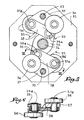
- Fig. 5 is a vertical section showing the arrangement of the mechanism considered.
- Fig. 6 is a detail section along the plane indicated in VI-VI in FIG. 4.
- the reference 31 designates the disc which is connected by the two opposite axes 33 to the input plate to form a rotating cage similar to that described with reference to FIG. 1.
- On each of the two axes 33 oscillates one of the two supports 37 fitted with rollers 36 intended to roll on the profiled disks of the fixed cam 35.
- each connecting rod 38 is articulated on the one hand to a lateral axis 39 carried by the spacer 39 keyed on the main shaft of the dobby 34 on the other hand on one of the two axes 37a provided on the support 37 in question for the mounting of the rollers 36 mad.
Landscapes
- Engineering & Computer Science (AREA)
- General Engineering & Computer Science (AREA)
- Mechanical Engineering (AREA)
- Textile Engineering (AREA)
- Looms (AREA)
- Transmission Devices (AREA)
- Auxiliary Weaving Apparatuses, Weavers' Tools, And Shuttles (AREA)
Abstract
Description
La présente invention a trait aux ratières du type rotatif pour métiers à tisser et elle concerne plus particulièrement les mécanismes modulateurs interposés entre l'arbre du métier et l'arbre principal de la ratière en vue d'assurer l'entraînement discontinu de ce dernier avec arrêt tous les 180°.The present invention relates to dobbies of the rotary type for weaving looms and it relates more particularly to the modulating mechanisms interposed between the loom of the loom and the main shaft of the dobby in order to ensure the discontinuous drive of the latter with stop every 180 °.
On a proposé différents types de mécanismes modulateurs pour ratières rotatives, certaines constructions connues reproduisant fidèlement des systèmes d'entraînement intermittent utilisés dans d'autres secteurs techniques.Different types of modulating mechanisms have been proposed for rotary dobbies, certain known constructions faithfully reproducing intermittent drive systems used in other technical sectors.
On se référera en premier lieu au Brevet français STAUBLI N° 80.05855/2 478 143 dont on a schématiquement rappelé l'agencement à la fig. 1 du dessin annexé aux présentes. Le mécanisme décrit comprend essentiellement une cage tournante qui est formée par un plateau d'entrée 1 et un disque 2 reliés l'un à l'autre par deux axes longitudinaux 3 et qui est montée folle sur l'arbre principal 4 de la ratière en étant entraînée en rotation par l'arbre du métier à tisser. Cet arbre 4 traverse librement une came fixe 5 du type complémentaire dont les deux disques constitutifs sont rigidement fixés au carter de la ratière ; contre cette came 5 sont appliquées deux paires de galets 6, chaque paire étant montée sur un support 7 qui oscille librement sur l'un des deux axes 3. La liaison articulée entre chaque support oscillant 7 et l'arbre 4 est assurée par un dé 8 qui, mobile à l'intérieur d'une coulisse radiale 7a dudit support et porté à pivotement par deux entretoises 9 solidaires de l'arbre 4, fait fonction de biellette d'entraînement.We will first refer to the French patent STAUBLI N ° 80.05855 / 2 478 143, the arrangement of which has been schematically recalled in FIG. 1 of the drawing appended hereto. The mechanism described essentially comprises a rotating cage which is formed by an
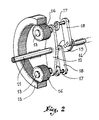
Un autre type connu de mécanismes modulateur est illustré par le Brevet U.S.A. STEINKE N° 3 407 678 dont l'agencement a été schématiquement rappelé à la fig. 2 du dessin annexé. Ici, les galets de commande sont remplacés par des pignons 16 qui sont montés fous sur des arbres 13 supportés à rotation par un flasque 12, lequel est calé sur l'arbre du métier 11. Chaque pignon 16 engrène avec une couronne dentée 15 rigidement fixée au carter fixe de la ratière, si bien que chaque arbre 13 est entraîné en rotation. Celui-ci comporte un prolongement 17 désaxé par rapport à l'axe dudit arbre, et la liaison entre chaque prolongement 17 et l'arbre principal 14 de la ratière est opérée à l'aide d'une biellette 18 attelée sur une entretoise 19 calée sur ledit arbre 4.Another known type of modulator mechanism is illustrated by the USA STEINKE Patent No. 3,407,678, the arrangement of which has been schematically recalled in FIG. 2 of the accompanying drawing. Here, the control rollers are replaced by
Plus récemment, on a proposé un agencement qui dérive en fait directement des deux systèmes ci-dessus rappelés. Comme illustré très schématiquement à la fig. 3, cet agencement fait à nouveau appel à deux paires de galets 26 montés sur deux supports opposés 27 qui oscillent autour d'axes 23 afin que lesdits galets portent sur une came fixe 25. La liaison entre chaque support 27 et l'arbre 24 de la ratière est réalisée, comme dans le cas du Brevet U.S.A. ci-dessus mentionné, par une biellette 28 attelée d'une part sur un axe latéral 27a dudit support 27, d'autre part sur une entretoise 29 calée sur l'arbre 24 précité.More recently, an arrangement has been proposed which in fact derives directly from the two systems mentioned above. As illustrated very schematically in FIG. 3, this arrangement again calls upon two pairs of
On comprend que pour qu'un tel agencement fonctionne de manière correcte en assurant l'équilibrage parfait des efforts qui s'exercent sur les deux supports oscillants 27 du système, il est indispensable que ceux-ci et les pièces qui les relient à l'arbre 24 de la ratière comportent une géométrie absolument identique, toute erreur, même minime, de dimensionnement ou de géométrie entraînant l'impossibilité de faire simultanément porter les quatre galets 26 sur les deux pistes de la came complémentaire 25 ; il n'y a dès lors plus qu'un seul support oscillant qui travaille, ce qui engendre un déséquilibre et une surcharge inadmissibles. Or, on sait qu'il est en pratique bien difficile d'éviter systématiquement tout défaut dans une fabrication en série.It is understood that for such an arrangement to function correctly while ensuring perfect balance of the forces exerted on the two
C'est à cet inconvénient qu'entend remédier la présente invention, laquelle a pour objet le mécanisme modulateur défini à la revendication 1.It is this drawback that the present invention intends to remedy, which relates to the modulator mechanism defined in
En fait l'invention consiste essentiellement, à la manière très schématiquement illustrée à la fig. 4 du dessin annexé, à opérer l'attelage de chaque biellette de liaison 38 avec le support oscillant 37 au niveau de l'axe 37a prévu sur ledit support 37 pour le montage de l'un des deux galets 36 de celui-ci.In fact the invention essentially consists, in the manner very schematically illustrated in FIG. 4 of the accompanying drawing, to operate the coupling of each connecting
Sans même évoquer l'économie réalisée par la suppression de l'un des quatre alésages prévus sur chaque support suivant le système illustré à la fig. 3, on conçoit que la confusion ou coïncidence du point d'attelage de la biellette de liaison sur le support oscillant avec l'axe de montage de l'un des deux galets de celui-ci évite toute conséquence fâcheuse résultant d'une erreur de géométrie et toute possibilité d'imprécision.Without even mentioning the savings made by eliminating one of the four bores provided on each support according to the system illustrated in fig. 3, it can be seen that the confusion or coincidence of the coupling point of the connecting rod on the oscillating support with the mounting axis of one of the two rollers thereof avoids any untoward consequence resulting from an error in geometry and any possibility imprecision.
On va maintenant donner une description plus détaillée d'une forme de réalisation du mécanisme modulateur suivant l'invention, forme de réalisation qui a été illustrée sur le dessin annexé dans lequel :We will now give a more detailed description of an embodiment of the modulator mechanism according to the invention, an embodiment which has been illustrated in the appended drawing in which:
Fig. 5 est une coupe verticale montrant l'agencement du mécanisme considéré.Fig. 5 is a vertical section showing the arrangement of the mechanism considered.
Fig. 6 est une coupe de détail suivant le plan indiqué en VI-VI en fig. 4.Fig. 6 is a detail section along the plane indicated in VI-VI in FIG. 4.
En fig. 5 la référence 31 désigne le disque qui est relié par les deux axes opposés 33 au plateau d'entrée pour constituer une cage tournante analogue à celle décrite en référence à la fig. 1. Sur chacun des deux axes 33 oscille l'un des deux supports 37 équipés des galets 36 destinés à rouler sur les disques profilés de la came fixe 35. Comme plus particulièrement visible en fig. 6, on peut vérifier que chaque biellette de liaison 38 s'articule d'une part à un axe latéral 39a porté par l'entretoise 39 calée sur l'arbre principal 34 de la ratière, d'autre part sur l'un des deux axes 37a prévus sur le support 37 considéré pour le montage des galets fous 36.In fig. 5 the
Le fonctionnement est identique à celui du mécanisme modulateur suivant la fig. 1, en ce sens que l'oscillation des deux supports 37 impartit, par l'intermédiaire des biellettes 38, à l'arbre 34 le mouvement discontinu désiré. Ainsi qu'on l'a exposé plus haut, l'articulation de chaque biellette 38 sur l'un des deux axes-supports 37a des galets 36 assure dans tous les cas l'équilibre des efforts qui s'exercent sur les deux supports 37.The operation is identical to that of the modulator mechanism according to FIG. 1, in the sense that the oscillation of the two supports 37 impart, by means of the
Il va de soi que l'invention est applicable à des mécanismes modulateurs comprenant plus de deux supports oscillants porte-galets.It goes without saying that the invention is applicable to modulating mechanisms comprising more than two oscillating roller carrier supports.
Claims (1)
Applications Claiming Priority (2)
| Application Number | Priority Date | Filing Date | Title |
|---|---|---|---|
| FR9003068 | 1990-03-06 | ||
| FR9003068A FR2659359B1 (en) | 1990-03-06 | 1990-03-06 | MODULATING MECHANISM FOR THE OPERATION OF ROTARY TYPE TEXTILE RAILS. |
Publications (2)
| Publication Number | Publication Date |
|---|---|
| EP0446155A1 true EP0446155A1 (en) | 1991-09-11 |
| EP0446155B1 EP0446155B1 (en) | 1995-05-24 |
Family
ID=9394596
Family Applications (1)
| Application Number | Title | Priority Date | Filing Date |
|---|---|---|---|
| EP91420077A Expired - Lifetime EP0446155B1 (en) | 1990-03-06 | 1991-03-05 | Modulating mechanism for the command of rotatory dobbies |
Country Status (6)
| Country | Link |
|---|---|
| US (1) | US5107901A (en) |
| EP (1) | EP0446155B1 (en) |
| JP (1) | JP2831479B2 (en) |
| DE (1) | DE69109899T2 (en) |
| ES (1) | ES2072581T3 (en) |
| FR (1) | FR2659359B1 (en) |
Cited By (1)
| Publication number | Priority date | Publication date | Assignee | Title |
|---|---|---|---|---|
| EP1712665A1 (en) * | 2005-04-13 | 2006-10-18 | NV Michel van de Wiele | Device for modulating a first rotational motion of an input shaft to a second, different from the first, rotational motion of an output shaft in textile machines |
Families Citing this family (9)
| Publication number | Priority date | Publication date | Assignee | Title |
|---|---|---|---|---|
| DE29500594U1 (en) * | 1995-01-16 | 1995-02-23 | Stäubli & Trumpelt GmbH, 95448 Bayreuth | Modulation gear for a rotary shaft machine in a weaving machine |
| US5653268A (en) * | 1995-01-16 | 1997-08-05 | Staubli Gmbh | Modulator mechanism for a rotary dobby in a loom |
| US7475708B2 (en) * | 2004-11-17 | 2009-01-13 | Groz-Beckert Kg | Shaft drive for heald shafts of weaving machines |
| FR2884527B1 (en) * | 2005-04-15 | 2007-07-13 | Staubli Faverges Sca | ARMOR CAM MECHANICS, METHOD OF ASSEMBLING SUCH A MECHANICAL AND WEAVING COMPRISING SUCH A MECHANICAL |
| DE502006006469D1 (en) * | 2006-11-24 | 2010-04-29 | Groz Beckert Kg | Gear for a weaving sheave drive |
| CN101806344B (en) * | 2010-03-29 | 2011-12-07 | 杨德利 | Bidirectional self-adaptive independent transmission system |
| CN104455075B (en) * | 2014-11-18 | 2017-07-11 | 杨德利 | The shaft transmission system of bidirectional self-adaptive three |
| CN110438621A (en) * | 2019-08-23 | 2019-11-12 | 江苏宋和宋智能科技有限公司 | A kind of rotary speed shifting mechanism and the weaving shedding motion with the mechanism |
| CN112095200B (en) * | 2020-09-22 | 2022-01-14 | 青海德瑞纺织品进出口有限公司 | Novel rotary dobby for spinning |
Citations (2)
| Publication number | Priority date | Publication date | Assignee | Title |
|---|---|---|---|---|
| EP0035954A1 (en) * | 1980-03-11 | 1981-09-16 | S.A. DES ETABLISSEMENTS STAUBLI (France) | Modulating mechanisms for actuating disc-dobbies |
| FR2625514A1 (en) * | 1988-01-05 | 1989-07-07 | Nuovo Pignone Spa | MODULATOR FOR CONTROLLING MACHINERY OF ARMOR ROTATING AT VERY HIGH SPEED |
Family Cites Families (3)
| Publication number | Priority date | Publication date | Assignee | Title |
|---|---|---|---|---|
| US3407678A (en) * | 1966-12-19 | 1968-10-29 | Ncr Co | Mechanism for producing rotary output motion with harmonic displacement characteristics |
| DE2841281C2 (en) * | 1978-09-22 | 1980-08-28 | Maschinenfabrik Carl Zangs Ag, 4150 Krefeld | Control for a rotary dobby |
| DE2937760B1 (en) * | 1979-09-19 | 1980-10-30 | Zangs Ag Maschf | Gear for the shedding mechanism of a weaving machine |
-
1990
- 1990-03-06 FR FR9003068A patent/FR2659359B1/en not_active Expired - Lifetime
-
1991
- 1991-03-01 US US07/663,180 patent/US5107901A/en not_active Expired - Lifetime
- 1991-03-05 EP EP91420077A patent/EP0446155B1/en not_active Expired - Lifetime
- 1991-03-05 ES ES91420077T patent/ES2072581T3/en not_active Expired - Lifetime
- 1991-03-05 DE DE69109899T patent/DE69109899T2/en not_active Expired - Fee Related
- 1991-03-06 JP JP3040228A patent/JP2831479B2/en not_active Expired - Lifetime
Patent Citations (2)
| Publication number | Priority date | Publication date | Assignee | Title |
|---|---|---|---|---|
| EP0035954A1 (en) * | 1980-03-11 | 1981-09-16 | S.A. DES ETABLISSEMENTS STAUBLI (France) | Modulating mechanisms for actuating disc-dobbies |
| FR2625514A1 (en) * | 1988-01-05 | 1989-07-07 | Nuovo Pignone Spa | MODULATOR FOR CONTROLLING MACHINERY OF ARMOR ROTATING AT VERY HIGH SPEED |
Non-Patent Citations (1)
| Title |
|---|
| MACHINE DESIGN. vol. 59, no. 1, 8 janvier 1987, CLEVELAND US page 128 FREDERICO STRASSER: "Controlling motions with cams" * |
Cited By (3)
| Publication number | Priority date | Publication date | Assignee | Title |
|---|---|---|---|---|
| EP1712665A1 (en) * | 2005-04-13 | 2006-10-18 | NV Michel van de Wiele | Device for modulating a first rotational motion of an input shaft to a second, different from the first, rotational motion of an output shaft in textile machines |
| BE1016493A3 (en) * | 2005-04-13 | 2006-12-05 | Wiele Michel Van De Nv | DEVICE FOR MODULATING A FIRST ROTARY MOVEMENT OF AN INCOMING AXLE TO A SECOND, DIFFERENT FROM THE FIRST, ROTARY MOVEMENT OF AN OUTGOING AXIS OF TEXTILE MACHINES. |
| US7506668B2 (en) | 2005-04-13 | 2009-03-24 | N.V. Michel Van De Wiele | Device for modulating a first rotational motion of an input shaft to a second, different from the first, rotational motion of an output shaft in textile machines |
Also Published As
| Publication number | Publication date |
|---|---|
| DE69109899T2 (en) | 1995-12-21 |
| DE69109899D1 (en) | 1995-06-29 |
| EP0446155B1 (en) | 1995-05-24 |
| ES2072581T3 (en) | 1995-07-16 |
| JP2831479B2 (en) | 1998-12-02 |
| JPH073568A (en) | 1995-01-06 |
| FR2659359A1 (en) | 1991-09-13 |
| FR2659359B1 (en) | 1992-08-28 |
| US5107901A (en) | 1992-04-28 |
Similar Documents
| Publication | Publication Date | Title |
|---|---|---|
| EP0446155B1 (en) | Modulating mechanism for the command of rotatory dobbies | |
| FR2716839A1 (en) | Device for removing cylinders from printing units of rotary printing machines. | |
| EP0849384B1 (en) | Shedding mechanism, method of assembly thereof and Jacuard loom with such a mechanism | |
| US4227554A (en) | Device for regulating the winding tension of woven fabric on a loom | |
| EP0580528A1 (en) | Levelling device for cam operated shedding mechanisms on looms | |
| EP0035954B1 (en) | Modulating mechanisms for actuating disc-dobbies | |
| FR2605374A1 (en) | THREE-DIMENSIONAL MOTION TRANSMISSION MECHANISM, COMPRISING FOUR AXES HAVING THE SAME POINT OF INTERSECTION | |
| FR2470175A1 (en) | DEVICE FOR MODIFYING THE POSITION OF THE COMB STRIPS IN WEAVING FABRICS FOR SPONGE FABRIC | |
| EP0564372B1 (en) | Offset printing machine | |
| CH627501A5 (en) | READING DEVICE FOR WEAVING MECHANICS. | |
| EP0566506B1 (en) | Device for reciprocating the knives in heavy centre-shed dobbies | |
| EP0274455B1 (en) | Negative dobby machines wth oscillating swing levers | |
| EP0443969B1 (en) | Controlling mechanism for the movement of the needle frame of a shedding device | |
| EP0462035B1 (en) | Centre-shed dobby for looms | |
| EP1743058A1 (en) | Level adjustment device, cam harness mounting mechanism incorporating said device and weaving machine fitted with said mechanism | |
| FR2624431A1 (en) | STAPLING MACHINE WITH OSCILLATING STAPLER HEAD | |
| FR2717143A1 (en) | Pivoting of automobile hatchback | |
| EP0539249B1 (en) | Vehicle windshield wiper with controlled means to vary the wiper pressure | |
| FR2492856A1 (en) | SEWING MACHINE HAVING A TRANSVERSALLY MOBILE TRAINING JACK | |
| EP0170618B1 (en) | Apparatus for reproducing at least one coloured surface on a photographic emulsion | |
| FR2520895A1 (en) | PROGRAMMER CONTROL DEVICE | |
| EP0325880B1 (en) | Braiding machine | |
| FR2475437A1 (en) | Rotary disc cutter for subdivision of sheet metal - uses two sets of rollers in pivot frame which inverts to switch drive from one set to other | |
| EP0681042A1 (en) | Driving system for reciprocating crank driven knife boxes | |
| FR2553109A1 (en) | MOBILE FORMATION MOVEMENT, ESPECIALLY FOR WIRED MOBILE CROWD MILLS |
Legal Events
| Date | Code | Title | Description |
|---|---|---|---|
| PUAI | Public reference made under article 153(3) epc to a published international application that has entered the european phase |
Free format text: ORIGINAL CODE: 0009012 |
|
| AK | Designated contracting states |
Kind code of ref document: A1 Designated state(s): BE CH DE ES FR IT LI |
|
| 17P | Request for examination filed |
Effective date: 19911029 |
|
| 17Q | First examination report despatched |
Effective date: 19931220 |
|
| GRAA | (expected) grant |
Free format text: ORIGINAL CODE: 0009210 |
|
| AK | Designated contracting states |
Kind code of ref document: B1 Designated state(s): BE CH DE ES FR IT LI |
|
| REF | Corresponds to: |
Ref document number: 69109899 Country of ref document: DE Date of ref document: 19950629 |
|
| REG | Reference to a national code |
Ref country code: ES Ref legal event code: FG2A Ref document number: 2072581 Country of ref document: ES Kind code of ref document: T3 |
|
| ITF | It: translation for a ep patent filed | ||
| PLBE | No opposition filed within time limit |
Free format text: ORIGINAL CODE: 0009261 |
|
| STAA | Information on the status of an ep patent application or granted ep patent |
Free format text: STATUS: NO OPPOSITION FILED WITHIN TIME LIMIT |
|
| 26N | No opposition filed | ||
| PGFP | Annual fee paid to national office [announced via postgrant information from national office to epo] |
Ref country code: ES Payment date: 20020225 Year of fee payment: 12 |
|
| PG25 | Lapsed in a contracting state [announced via postgrant information from national office to epo] |
Ref country code: ES Free format text: LAPSE BECAUSE OF NON-PAYMENT OF DUE FEES Effective date: 20030306 |
|
| REG | Reference to a national code |
Ref country code: ES Ref legal event code: FD2A Effective date: 20030306 |
|
| PGFP | Annual fee paid to national office [announced via postgrant information from national office to epo] |
Ref country code: CH Payment date: 20080313 Year of fee payment: 18 |
|
| PGFP | Annual fee paid to national office [announced via postgrant information from national office to epo] |
Ref country code: FR Payment date: 20080228 Year of fee payment: 18 |
|
| PGFP | Annual fee paid to national office [announced via postgrant information from national office to epo] |
Ref country code: DE Payment date: 20090312 Year of fee payment: 19 |
|
| REG | Reference to a national code |
Ref country code: CH Ref legal event code: PL |
|
| REG | Reference to a national code |
Ref country code: FR Ref legal event code: ST Effective date: 20091130 |
|
| PG25 | Lapsed in a contracting state [announced via postgrant information from national office to epo] |
Ref country code: CH Free format text: LAPSE BECAUSE OF NON-PAYMENT OF DUE FEES Effective date: 20090331 Ref country code: LI Free format text: LAPSE BECAUSE OF NON-PAYMENT OF DUE FEES Effective date: 20090331 |
|
| PG25 | Lapsed in a contracting state [announced via postgrant information from national office to epo] |
Ref country code: FR Free format text: LAPSE BECAUSE OF NON-PAYMENT OF DUE FEES Effective date: 20091123 |
|
| PGFP | Annual fee paid to national office [announced via postgrant information from national office to epo] |
Ref country code: IT Payment date: 20100325 Year of fee payment: 20 |
|
| PGFP | Annual fee paid to national office [announced via postgrant information from national office to epo] |
Ref country code: BE Payment date: 20100505 Year of fee payment: 20 |
|
| PG25 | Lapsed in a contracting state [announced via postgrant information from national office to epo] |
Ref country code: DE Free format text: LAPSE BECAUSE OF NON-PAYMENT OF DUE FEES Effective date: 20101001 |
|
| BE20 | Be: patent expired |
Owner name: S.A. DES ETS *STAUBLI (FRANCE) Effective date: 20110305 |