EP0445633A1 - Verfahren zum Schweissen metallischer Balken und metallische Balken hergestellt nach dem Verfahren - Google Patents
Verfahren zum Schweissen metallischer Balken und metallische Balken hergestellt nach dem Verfahren Download PDFInfo
- Publication number
- EP0445633A1 EP0445633A1 EP91102882A EP91102882A EP0445633A1 EP 0445633 A1 EP0445633 A1 EP 0445633A1 EP 91102882 A EP91102882 A EP 91102882A EP 91102882 A EP91102882 A EP 91102882A EP 0445633 A1 EP0445633 A1 EP 0445633A1
- Authority
- EP
- European Patent Office
- Prior art keywords
- laser beam
- coupling
- metallic
- welding
- beams
- Prior art date
- Legal status (The legal status is an assumption and is not a legal conclusion. Google has not performed a legal analysis and makes no representation as to the accuracy of the status listed.)
- Withdrawn
Links
Images
Classifications
-
- B—PERFORMING OPERATIONS; TRANSPORTING
- B23—MACHINE TOOLS; METAL-WORKING NOT OTHERWISE PROVIDED FOR
- B23K—SOLDERING OR UNSOLDERING; WELDING; CLADDING OR PLATING BY SOLDERING OR WELDING; CUTTING BY APPLYING HEAT LOCALLY, e.g. FLAME CUTTING; WORKING BY LASER BEAM
- B23K26/00—Working by laser beam, e.g. welding, cutting or boring
- B23K26/02—Positioning or observing the workpiece, e.g. with respect to the point of impact; Aligning, aiming or focusing the laser beam
- B23K26/04—Automatically aligning, aiming or focusing the laser beam, e.g. using the back-scattered light
-
- B—PERFORMING OPERATIONS; TRANSPORTING
- B23—MACHINE TOOLS; METAL-WORKING NOT OTHERWISE PROVIDED FOR
- B23K—SOLDERING OR UNSOLDERING; WELDING; CLADDING OR PLATING BY SOLDERING OR WELDING; CUTTING BY APPLYING HEAT LOCALLY, e.g. FLAME CUTTING; WORKING BY LASER BEAM
- B23K26/00—Working by laser beam, e.g. welding, cutting or boring
- B23K26/20—Bonding
- B23K26/21—Bonding by welding
- B23K26/24—Seam welding
- B23K26/242—Fillet welding, i.e. involving a weld of substantially triangular cross section joining two parts
-
- B—PERFORMING OPERATIONS; TRANSPORTING
- B23—MACHINE TOOLS; METAL-WORKING NOT OTHERWISE PROVIDED FOR
- B23K—SOLDERING OR UNSOLDERING; WELDING; CLADDING OR PLATING BY SOLDERING OR WELDING; CUTTING BY APPLYING HEAT LOCALLY, e.g. FLAME CUTTING; WORKING BY LASER BEAM
- B23K26/00—Working by laser beam, e.g. welding, cutting or boring
- B23K26/20—Bonding
- B23K26/21—Bonding by welding
- B23K26/24—Seam welding
- B23K26/26—Seam welding of rectilinear seams
-
- B—PERFORMING OPERATIONS; TRANSPORTING
- B23—MACHINE TOOLS; METAL-WORKING NOT OTHERWISE PROVIDED FOR
- B23K—SOLDERING OR UNSOLDERING; WELDING; CLADDING OR PLATING BY SOLDERING OR WELDING; CUTTING BY APPLYING HEAT LOCALLY, e.g. FLAME CUTTING; WORKING BY LASER BEAM
- B23K33/00—Specially-profiled edge portions of workpieces for making soldering or welding connections; Filling the seams formed thereby
Definitions
- This invention concerns a method to weld metallic beams.
- the invention concerns a method suitable to obtain continuous welding of the component parts of metallic beams by applying a laser beam.
- the method of the invention is used advantageously for the production of metallic beams having their component elements arranged at a right angle to each other.
- the invention concerns also the metallic beams produced by the above method.
- the method of the invention can be employed also for the jointing of metallic elements other than beams.
- the state of the art covers methods to weld metallic beams and, in particular, beams having great lengthwise dimensions.
- metallic beams are meant all those beams having an H-shaped conformation and therefore a main central element and two flange elements, or else T-beams, angle bars, channel sections and Z sections, all such metallic beams belonging to the general category of beams with an open section.
- beam configurations are also included such as, for instance, the so-called box-type beams having a closed section.
- the above metallic beams include two or more elements positioned at a right angle to each other which have to be welded together to form the finished beam.
- the welds have to be made either at lateral positions on an outer edge of the flange element or elements, as is the case with angle bars, channel sections and Z sections, or at central intermediate positions on the flange element or elements in the case of H-beams or T-beams.
- welds are of the submerged arc welding type with the use of filler rod and are carried out on appropriate equipment, which comprises one or more welding heads driven by a suitable mechanism so as to move along the line of the joint to be welded.
- the welding heads are fitted to trolleys able to run on rails parallel to the joints to be welded, but it is also possible to arrange that the parts to be welded are themselves moved so as to pass along the welding heads.
- a laser beam is focused by lenses or mirrors on very small surfaces, on which are produced high densities of power that bring practically all materials to a molten state.
- the laser beam has a conical terminal conformation and is protected by a working head generally having a prismatic conformation, which provides application of the laser beam to the parts to be welded.
- Inert protective gases are also employed which prevent oxidation of the molten portion and improve the transmission of energy to the parts to be joined.
- the laser beam although it offers the above advantages, is applied at present only to the butt jointing of metallic elements or in making joints at the outer edges of orthogonal connections such as angle bars, channel sections Z sections or the like.
- the elements to be united have to be processed beforehand with a given degree of precision; the other welding techniques, owing to their intrinsic characteristics, enable a relative working remedy to be made with regard to any lack of precision in the parts to be joined.
- the present applicant has studied, tested and obtained a method for welding with laser beams, the method being suitable to overcome the problems of the state of the art.
- the invention concerns also the metallic beams produced with this method.
- the method of the invention provides for the metallic beam elements which have to be welded together in substantially orthogonal positions, to be worked beforehand in a suitable manner. Such working consists in preparation of the elements for coupling together in a prismatic manner, whereby the end of one of the elements is shaped prismatically, whereas a mating prismatic seating is machined in the other element.
- This processing may therefore be conical, or semi-conical or of another similar type.
- the conical shape thus processed may have a variable angular value, depending on the technical features of the application and of the laser device employed.
- the conical shape whatever it may be, has to be such as to enable the laser beam used to be correctly focused, that is to say, the axis of the cone consisting of the laser beam has to lie on a plane containing the conical surfaces to be united.
- the processing of the elements to be coupled will enable the usual laser welding heads to be brought to the welding zones.
- a traditional welding operation of a type with an arc in an inert gas (CO2) may cooperate with the laser beam welding operation.
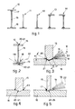
- Fig.1 shows some currently used types of metallic beams to which the method of the invention can be applied.
- H-beams are referenced with 10, overturned T-beams with 11, angle bars with 12, channel sections with 13 and Z-sections with 14.
- These types of metallic beams comprise a main central element 15 and at least one flange element 16; these elements 15-16 have to be joined to each other orthogonally by means of a weld which has to be made on four sides of the central element 15 and along the whole length of each metallic beam.
- the welds are referenced with 17 in Fig.1 and represent the type employed in the state of the art and made with filler rod.
- Fig.2 is a diagram of the application of the invention to a metallic H-beam 10.
- the welds to be made with a laser beam and shown diagrammatically with a cone 18 are carried out continuously without filler rod along the whole length of the metallic beam 10 along the orthogonal joint between the central element 15 and flange element 16 in the neighbourhood of the central line thereof.
- the welding is performed with a working head 19 that may possibly cooperate with an analogous counterpart working head 119.
- the working heads 19-119 will advantageously have a prismatic end conformation to protect and bring a laser beam 18 to the zone to be welded.
- the central metallic beam element 15 has conically conformed ends 20 to cooperate with a mating conical seating 21 included in each flange element 16. These conically conformed ends 20 and seatings 21 are readied beforehand, by a simple milling operation for instance, on the central and flange elements 15-16 to be joined.
- the working head 19-119 is equipped with suitable self-positioning sensors to compensate, during the welding, any processing errors included in the central and flange elements 15-16 to be coupled.
- the conical portions 20-21 on the central and flange elements 15-16 may also undergo a surface finishing process before being coupled together.
- the angle of taper ( ⁇ ) of the conical processed surfaces of the central and flange elements 15-16 is a function of the conical conformation of the laser beam 18 and of the conditions of application of that beam 18. In any event the angle of taper ( ⁇ ) has to be such that the axis 22 of the cone formed by the laser beam 18 lies on the surface " ⁇ " to be welded, namely on the plane containing the conical portions 20-21.
- the focus of the laser beam 18 may fall within or outside the length "l" of the joint of the two conical portions 20-21, depending on the technological requirements of the weld to be made.
- Fig.3 shows two equal counterpart portions 20 equal to the two mating portions 21.
- Fig.4 shows a possible variant of the method of the preceding figures, according to which in special conditions of application a slight seam weld 23 of a traditional type can be added to the laser weld described above for exceptional reasons, possibly of an aesthetic nature, or for surface finishing.
- Fig.5 shows a solution which can be employed in particular for central beam elements 15 of a limited thickness or for box-type metallic beams; according to this solution the central element 15 is conformed terminally with a semi-conical end 24 to be united to a mating semi-conical seating 25 provided in the flange element 16.
- the welding by laser beam 18 can be carried out on one side of the joint between the central and flange elements 15-16.
- a traditional weld 17 with filler rod can be made on the other side of the joint.
Landscapes
- Physics & Mathematics (AREA)
- Optics & Photonics (AREA)
- Engineering & Computer Science (AREA)
- Mechanical Engineering (AREA)
- Plasma & Fusion (AREA)
- Laser Beam Processing (AREA)
- Welding Or Cutting Using Electron Beams (AREA)
Applications Claiming Priority (2)
| Application Number | Priority Date | Filing Date | Title |
|---|---|---|---|
| IT8334290 | 1990-03-05 | ||
| IT83342A IT1239663B (it) | 1990-03-05 | 1990-03-05 | Procedimento di saldatura per travi metalliche e travi metalliche cosi' ottenute |
Publications (1)
| Publication Number | Publication Date |
|---|---|
| EP0445633A1 true EP0445633A1 (de) | 1991-09-11 |
Family
ID=11320428
Family Applications (1)
| Application Number | Title | Priority Date | Filing Date |
|---|---|---|---|
| EP91102882A Withdrawn EP0445633A1 (de) | 1990-03-05 | 1991-02-27 | Verfahren zum Schweissen metallischer Balken und metallische Balken hergestellt nach dem Verfahren |
Country Status (2)
| Country | Link |
|---|---|
| EP (1) | EP0445633A1 (de) |
| IT (1) | IT1239663B (de) |
Cited By (10)
| Publication number | Priority date | Publication date | Assignee | Title |
|---|---|---|---|---|
| EP0558880A1 (de) * | 1991-09-16 | 1993-09-08 | BÖHLER YBBSTALWERKE Ges.m.b.H. | Nachschleifbares Spanermesser |
| WO1994014568A1 (fr) * | 1991-06-27 | 1994-07-07 | Mecanique Creusot Loire | Procede d'assemblage de deux pieces en tole, assemblage metallique et structure en tole de blindage obtenus par ce procede |
| EP0626231A1 (de) * | 1993-05-25 | 1994-11-30 | Societe Nationale D'etude Et De Construction De Moteurs D'aviation "Snecma" | Laserschweissverfahren um zwei metallischen Werkstücken |
| EP0685610A1 (de) * | 1994-06-03 | 1995-12-06 | Thyssen Stahl Aktiengesellschaft | Aus einem Steg und mindestens einem Flansch durch Strahlungsenergie zusammengeschweisster Profilträger aus Metall, insbesondere Stahl und Verfahren zu seiner Herstellung |
| US5841098A (en) * | 1996-09-27 | 1998-11-24 | Daimler-Benz Aerospace Airbus Gmbh | Method and apparatus for laser welding sectional members onto large-format aluminum structural components |
| US6998569B2 (en) | 2002-07-09 | 2006-02-14 | Airbus Deutschland Gmbh | Apparatus and method for regulating the weld seam position during laser welding of a butt-jointed workpiece |
| JP2013112085A (ja) * | 2011-11-26 | 2013-06-10 | Tachi S Co Ltd | シート・トラック |
| CN103406667A (zh) * | 2013-08-31 | 2013-11-27 | 南京煜宸激光科技有限公司 | 一种不锈钢薄板角焊缝的激光焊接方法及其夹具 |
| WO2016047008A1 (ja) * | 2014-09-26 | 2016-03-31 | 日新製鋼株式会社 | 差厚材のレーザ溶接方法及び該方法を用いた差厚溶接部材 |
| WO2018107313A1 (zh) * | 2016-12-12 | 2018-06-21 | 机械科学研究总院青岛分院有限公司 | 一种QCr0.8与高强不锈钢的CMT焊接工艺 |
Citations (3)
| Publication number | Priority date | Publication date | Assignee | Title |
|---|---|---|---|---|
| DE2408680A1 (de) * | 1974-02-22 | 1975-09-04 | Maschf Augsburg Nuernberg Ag | Mittel zum zentrieren von hohldrehkoerpern und vorrichtung zum herstellen des zentriermittels |
| EP0288884A1 (de) * | 1987-04-22 | 1988-11-02 | Bernd Büdenbender | Anordnung zum VerschweiBen von stumpf gegeneinanderzulegenden Flanken von Metallblechen, Kunstofftafeln oder dergleichen |
| DE3827297A1 (de) * | 1988-08-11 | 1990-02-15 | Fraunhofer Ges Forschung | Vorrichtung und verfahren zum fuegen von werkstuecken mit laserstrahlung |
-
1990
- 1990-03-05 IT IT83342A patent/IT1239663B/it active IP Right Grant
-
1991
- 1991-02-27 EP EP91102882A patent/EP0445633A1/de not_active Withdrawn
Patent Citations (3)
| Publication number | Priority date | Publication date | Assignee | Title |
|---|---|---|---|---|
| DE2408680A1 (de) * | 1974-02-22 | 1975-09-04 | Maschf Augsburg Nuernberg Ag | Mittel zum zentrieren von hohldrehkoerpern und vorrichtung zum herstellen des zentriermittels |
| EP0288884A1 (de) * | 1987-04-22 | 1988-11-02 | Bernd Büdenbender | Anordnung zum VerschweiBen von stumpf gegeneinanderzulegenden Flanken von Metallblechen, Kunstofftafeln oder dergleichen |
| DE3827297A1 (de) * | 1988-08-11 | 1990-02-15 | Fraunhofer Ges Forschung | Vorrichtung und verfahren zum fuegen von werkstuecken mit laserstrahlung |
Cited By (16)
| Publication number | Priority date | Publication date | Assignee | Title |
|---|---|---|---|---|
| WO1994014568A1 (fr) * | 1991-06-27 | 1994-07-07 | Mecanique Creusot Loire | Procede d'assemblage de deux pieces en tole, assemblage metallique et structure en tole de blindage obtenus par ce procede |
| EP0558880A1 (de) * | 1991-09-16 | 1993-09-08 | BÖHLER YBBSTALWERKE Ges.m.b.H. | Nachschleifbares Spanermesser |
| EP0626231A1 (de) * | 1993-05-25 | 1994-11-30 | Societe Nationale D'etude Et De Construction De Moteurs D'aviation "Snecma" | Laserschweissverfahren um zwei metallischen Werkstücken |
| FR2705603A1 (fr) * | 1993-05-25 | 1994-12-02 | Snecma | Procédé de soudage laser d'un assemblage de deux pièces métalliques. |
| US5483034A (en) * | 1993-05-25 | 1996-01-09 | Societe Nationale D'etude Et De Construction De Moteurs D'aviation "Snecma" | Laser welding process for an assembly of two metal parts |
| EP0685610A1 (de) * | 1994-06-03 | 1995-12-06 | Thyssen Stahl Aktiengesellschaft | Aus einem Steg und mindestens einem Flansch durch Strahlungsenergie zusammengeschweisster Profilträger aus Metall, insbesondere Stahl und Verfahren zu seiner Herstellung |
| US5841098A (en) * | 1996-09-27 | 1998-11-24 | Daimler-Benz Aerospace Airbus Gmbh | Method and apparatus for laser welding sectional members onto large-format aluminum structural components |
| US6998569B2 (en) | 2002-07-09 | 2006-02-14 | Airbus Deutschland Gmbh | Apparatus and method for regulating the weld seam position during laser welding of a butt-jointed workpiece |
| JP2013112085A (ja) * | 2011-11-26 | 2013-06-10 | Tachi S Co Ltd | シート・トラック |
| CN103406667A (zh) * | 2013-08-31 | 2013-11-27 | 南京煜宸激光科技有限公司 | 一种不锈钢薄板角焊缝的激光焊接方法及其夹具 |
| WO2016047008A1 (ja) * | 2014-09-26 | 2016-03-31 | 日新製鋼株式会社 | 差厚材のレーザ溶接方法及び該方法を用いた差厚溶接部材 |
| CN107073649A (zh) * | 2014-09-26 | 2017-08-18 | 日新制钢株式会社 | 差厚材料的激光焊接方法及使用该方法的差厚焊接部件 |
| RU2636425C1 (ru) * | 2014-09-26 | 2017-11-23 | Ниссин Стил Ко., Лтд. | Способ лазерной сварки материалов, имеющих разные толщины |
| US9993896B2 (en) | 2014-09-26 | 2018-06-12 | Nisshin Steel Co., Ltd. | Method for laser welding of materials having different thicknesses |
| CN107073649B (zh) * | 2014-09-26 | 2018-07-10 | 日新制钢株式会社 | 差厚材料的激光焊接方法 |
| WO2018107313A1 (zh) * | 2016-12-12 | 2018-06-21 | 机械科学研究总院青岛分院有限公司 | 一种QCr0.8与高强不锈钢的CMT焊接工艺 |
Also Published As
| Publication number | Publication date |
|---|---|
| IT9083342A1 (it) | 1991-09-05 |
| IT1239663B (it) | 1993-11-11 |
| IT9083342A0 (it) | 1990-03-05 |
Similar Documents
| Publication | Publication Date | Title |
|---|---|---|
| EP0129962B1 (de) | Laserstrahlschweissen | |
| Vollertsen et al. | Welding thick steel plates with fibre lasers and GMAW | |
| EP0445633A1 (de) | Verfahren zum Schweissen metallischer Balken und metallische Balken hergestellt nach dem Verfahren | |
| DE59500953D1 (de) | Verfahren zum vorbereiten der fügebereiche beschichteter werkstücke zum schweissen mit laserstrahlung und überlappstoss zum schweissen beschichteter werkstücke | |
| JPS57106489A (en) | Laser joining method | |
| Coste et al. | Application of vision to laser welding: Increase of operating tolerances using beam-oscillation and filler-wire | |
| Vollertsen et al. | Defects and process tolerances in welding of thick plates | |
| JPH02137688A (ja) | レーザ加工装置 | |
| CA2243461A1 (en) | Overlapping joint for laser welding of tailored blanks | |
| SU1006138A1 (ru) | Способ двухсторонней автоматической сварки стыковых соединений | |
| JPH07266068A (ja) | アルミニウム又はアルミニウム合金部材のレーザ溶接方法 | |
| CN114669873B (zh) | 中厚板钛合金t型接头大功率光纤激光双枪对称焊接方法 | |
| JPS59206190A (ja) | 溶接方法 | |
| JPH01202385A (ja) | 金属板材のレーザ溶接方法 | |
| Salminen et al. | Effect of welding parameters on high-power diode laser welding of thin sheet | |
| JP2703450B2 (ja) | レーザ溶接におけるレーザビーム照射位置の設定方法 | |
| RU2278008C2 (ru) | Способ сварки толстостенных крупногабаритных деталей | |
| Jernstroem | Hybrid welding of hollow section beams for a telescopic lifter | |
| SU1687401A1 (ru) | Способ двухсторонней электронно-лучевой сварки | |
| JP3139953B2 (ja) | 縦振動レーザ仮付け溶接方法 | |
| DE19526571A1 (de) | Verfahren zur Reduktion der Nahtaufwölbung bei der Erzeugung von lasergeschweißten I-Stößen durch die Anschrägung der Blechkanten vermittels gezielter Einstellung der Polarisationseigenschaften der Laserstrahlung bezüglich der Bearbeitungsrichtung | |
| JPH034305B2 (de) | ||
| JPH077039Y2 (ja) | 溶接組立h形鋼の溶接接合に使用する裏当金 | |
| JPH03110089A (ja) | 突合せレーザ溶接方法 | |
| JPS6384787A (ja) | 鋼帯のレ−ザ−溶接方法 |
Legal Events
| Date | Code | Title | Description |
|---|---|---|---|
| PUAI | Public reference made under article 153(3) epc to a published international application that has entered the european phase |
Free format text: ORIGINAL CODE: 0009012 |
|
| AK | Designated contracting states |
Kind code of ref document: A1 Designated state(s): AT BE CH DE DK ES FR GB GR LI LU NL SE |
|
| STAA | Information on the status of an ep patent application or granted ep patent |
Free format text: STATUS: THE APPLICATION HAS BEEN WITHDRAWN |
|
| 18W | Application withdrawn |
Withdrawal date: 19920116 |