EP0445322A1 - Dispositif de traitement médical par ondes de choc avec sonde ultrasonique interchangeable - Google Patents
Dispositif de traitement médical par ondes de choc avec sonde ultrasonique interchangeable Download PDFInfo
- Publication number
- EP0445322A1 EP0445322A1 EP90104278A EP90104278A EP0445322A1 EP 0445322 A1 EP0445322 A1 EP 0445322A1 EP 90104278 A EP90104278 A EP 90104278A EP 90104278 A EP90104278 A EP 90104278A EP 0445322 A1 EP0445322 A1 EP 0445322A1
- Authority
- EP
- European Patent Office
- Prior art keywords
- shock wave
- ultrasonic wave
- imaging ultrasonic
- shock
- probe
- Prior art date
- Legal status (The legal status is an assumption and is not a legal conclusion. Google has not performed a legal analysis and makes no representation as to the accuracy of the status listed.)
- Granted
Links
Images


Classifications
-
- A—HUMAN NECESSITIES
- A61—MEDICAL OR VETERINARY SCIENCE; HYGIENE
- A61B—DIAGNOSIS; SURGERY; IDENTIFICATION
- A61B17/00—Surgical instruments, devices or methods, e.g. tourniquets
- A61B17/22—Implements for squeezing-off ulcers or the like on the inside of inner organs of the body; Implements for scraping-out cavities of body organs, e.g. bones; Calculus removers; Calculus smashing apparatus; Apparatus for removing obstructions in blood vessels, not otherwise provided for
- A61B17/225—Implements for squeezing-off ulcers or the like on the inside of inner organs of the body; Implements for scraping-out cavities of body organs, e.g. bones; Calculus removers; Calculus smashing apparatus; Apparatus for removing obstructions in blood vessels, not otherwise provided for for extracorporeal shock wave lithotripsy [ESWL], e.g. by using ultrasonic waves
- A61B17/2256—Implements for squeezing-off ulcers or the like on the inside of inner organs of the body; Implements for scraping-out cavities of body organs, e.g. bones; Calculus removers; Calculus smashing apparatus; Apparatus for removing obstructions in blood vessels, not otherwise provided for for extracorporeal shock wave lithotripsy [ESWL], e.g. by using ultrasonic waves with means for locating or checking the concrement, e.g. X-ray apparatus, imaging means
- A61B17/2258—Implements for squeezing-off ulcers or the like on the inside of inner organs of the body; Implements for scraping-out cavities of body organs, e.g. bones; Calculus removers; Calculus smashing apparatus; Apparatus for removing obstructions in blood vessels, not otherwise provided for for extracorporeal shock wave lithotripsy [ESWL], e.g. by using ultrasonic waves with means for locating or checking the concrement, e.g. X-ray apparatus, imaging means integrated in a central portion of the shock wave apparatus
Definitions
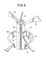
- This shock wave applicator 17 is equipped with a tilting mechanism for the shock wave transducer 15 and the imaging ultrasonic wave probe 16 so that the shock wave transducer 15 and the imaging ultrasonic wave probe 16 can be tilted to a desired direction toward the patient 32.
- the tilting mechanism comprises a couple of symmetrically arranged connectors 83, each of which having a first guide 82 at a top which is slidably engaged to a circular guide rail 81.
- the circular guide rail 81 is suspended by a suspension frame 80 which can suspend the entire shock wave applicator 17, and is curved such that it has a shape of a part of circle centered around a middle of the bottom face 16a of the imaging ultrasonic wave probe 16.
- Each connector 83 has two bottom ends one of which is connected to a top end portion of the housing pipe 54 while another one of which is connected to a vertical guide rail 84 provided parallel to the housing pipe 54 by the shock wave transducer 15.
- the shock wave transducer 15 is connected with the vertical rails 84 through second guides 85 attached at an edge of the shock wave transducer 15 which are slidably engaged with the vertical guide rails 84.
- Each of the vertical guide rails 84 has a stopper 84a at a bottom end to prevent the second guide 85 from disengaging off the vertical guide rail 84.
- a driver unit 36 for moving the shock wave transducer 15 in a direction E with respect to the housing pipe 54.
- This driver unit 36 comprises a rack 36a fixed on a side face of the housing pipe 54, a pinion gear 36b to be engaged with the rack 36a, a motor 36c as a source of driving power whose driving axis is connected to the pinion gear 36b, and a supporting member 36d for supporting the motor 36c with respect to the connecting member 43.
- the driver unit 36 moves the shock wave transducer 15 in a desired manner indicated by a control signal supplied from the position controller 30 appeared in Fig. 3.
- the reading of the scale markings read by the photo sensor 90b is signaled to the position controller 30, which in turn controls rotation angle of the driving axis of the motor 36c such that the position of the shock wave transducer 15 with respect to the imaging ultrasonic wave probe 16 is controlled in a desired manner.
- the position controller 30 controls rotation angle of the driving axis of the motor 36c such that the position of the shock wave transducer 15 with respect to the imaging ultrasonic wave probe 16 is controlled in a desired manner.
- the position controller 30 controls rotation angle of the driving axis of the motor 36c such that the position of the shock wave transducer 15 with respect to the imaging ultrasonic wave probe 16 is controlled in a desired manner.
- the lower pipe section 43b and the upper pipe section 51b function to keep the housing pipe 54 from tilting with respect to the connecting member 43, while the O-ring 52 function to prevent leakage of the water contained inside the water bag 33 even when the shock wave transducer 15 is moved in the direction E.
- an additional reinforcement member 75 made of rubber harder than that of the bottom face 37, at the inner side wall portion 37c, which is held fixed on the inner side wall portion 37c by a band 74, and an elastic ring shaped sponge 76 attached to the end portion of the imaging ultrasonic wave probe 16.
- imaging ultrasonic wave probe 16 of different frequencies depending on depths of the concretion to be disintegrated.
- imaging ultrasonic wave probes16 of different frequencies depending on physical constitution of the patient, such as the imaging ultrasonic wave probe 16 of low frequency for a muscular patient, and the imaging ultrasonic wave probe 16 of high frequency for a less muscular patient.
- the water bag 33 of the shock wave applicator 17 is placed over the body surface 32S of the patient 32 above the organ 38, with the imaging ultrasonic wave probe 16 contacting the body surface 32S.
- the concretion 39 can be displayed at a center of the displayed image, and this also helps a quick and easy apprehension of the concretion 39. Also, because the relative position of the shock wave transducer 15 with respect to the imaging ultrasonic wave probe 16 is adjustable, the treatment operation become easier.
- a quick and easy apprehension of the concretion 39 is possible because a very clear image without influences of the water or the bottom face 37 of the water bag 33 is obtainable as a result of the fact that the imaging ultrasonic wave probe 16 is contacting the body surface 32S.
- the water bag 33 can easily be stretched or contracted in a vertical direction, and the adjustment of the relative position of the shock wave transducer 15 with respect to the imaging ultrasonic wave probe 16 becomes easier.
- the leakage of the water from the water bag 33 in moving the shock wave transducer 15 is prevented by the O-ring 52 provided between the connecting member 43 and the housing pipe 54.
- the focal point 41a of the ultrasonic shock wave from the shock wave transducer 15 is indicated on the display unit 27 by the marker 26, an accurate treatment can be performed easily.
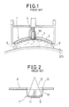
- a configuration of a portion C in Fig. 4, which is shown in detail in Fig. 8, may be altered to that shown in Fig. 11.
- the bottom face 37 of the water bag 33 is extended to cover the bottom face 16a of the imaging ultrasonic wave probe 16, while at the lower end of the housing pipe 54, which is shorter than the imaging ultrasonic wave probe 16 in this case, there is provide an O-ring 54d for preventing the water from entering into the housing pipe 54, which is contacting the side face of the imaging ultrasonic wave probe 16.
- the water that comes between the imaging ultrasonic wave probe 16 and the body surface 32S possesses an acoustic impedance close to that of a human body, the efficient transmission of the ultrasonic wave is possible.
- the imaging ultrasonic wave probe 16 may be made to be movable with respect to the shock wave transducer 15.
Landscapes
- Health & Medical Sciences (AREA)
- Surgery (AREA)
- Nuclear Medicine, Radiotherapy & Molecular Imaging (AREA)
- Life Sciences & Earth Sciences (AREA)
- Biomedical Technology (AREA)
- Molecular Biology (AREA)
- Orthopedic Medicine & Surgery (AREA)
- Engineering & Computer Science (AREA)
- Radiology & Medical Imaging (AREA)
- Heart & Thoracic Surgery (AREA)
- Medical Informatics (AREA)
- Vascular Medicine (AREA)
- Animal Behavior & Ethology (AREA)
- General Health & Medical Sciences (AREA)
- Public Health (AREA)
- Veterinary Medicine (AREA)
- Surgical Instruments (AREA)
- Ultra Sonic Daignosis Equipment (AREA)
Priority Applications (3)
| Application Number | Priority Date | Filing Date | Title |
|---|---|---|---|
| DE1990625165 DE69025165T2 (de) | 1990-03-06 | 1990-03-06 | Medizinische Vorrichtung zur Stosswellenbehandlung mit auswechselbarer Ultraschallsonde |
| EP90104278A EP0445322B1 (fr) | 1990-03-06 | 1990-03-06 | Dispositif de traitement médical par ondes de choc avec sonde ultrasonique interchangeable |
| US07/807,617 US5165412A (en) | 1990-03-05 | 1991-12-13 | Shock wave medical treatment apparatus with exchangeable imaging ultrasonic wave probe |
Applications Claiming Priority (1)
| Application Number | Priority Date | Filing Date | Title |
|---|---|---|---|
| EP90104278A EP0445322B1 (fr) | 1990-03-06 | 1990-03-06 | Dispositif de traitement médical par ondes de choc avec sonde ultrasonique interchangeable |
Publications (2)
| Publication Number | Publication Date |
|---|---|
| EP0445322A1 true EP0445322A1 (fr) | 1991-09-11 |
| EP0445322B1 EP0445322B1 (fr) | 1996-01-31 |
Family
ID=8203721
Family Applications (1)
| Application Number | Title | Priority Date | Filing Date |
|---|---|---|---|
| EP90104278A Expired - Lifetime EP0445322B1 (fr) | 1990-03-05 | 1990-03-06 | Dispositif de traitement médical par ondes de choc avec sonde ultrasonique interchangeable |
Country Status (2)
| Country | Link |
|---|---|
| EP (1) | EP0445322B1 (fr) |
| DE (1) | DE69025165T2 (fr) |
Cited By (2)
| Publication number | Priority date | Publication date | Assignee | Title |
|---|---|---|---|---|
| FR2747559A1 (fr) * | 1996-04-18 | 1997-10-24 | Siemens Ag | Appareil de therapie comportant un reglage simple d'une distance souhaitee par rapport a un point de reference |
| WO2002047560A1 (fr) * | 2000-12-15 | 2002-06-20 | Dornier Medtech Holding International Gmbh | Soufflet de couplage pour therapie a ondes de choc |
Families Citing this family (3)
| Publication number | Priority date | Publication date | Assignee | Title |
|---|---|---|---|---|
| DE10007858C1 (de) * | 2000-02-21 | 2001-12-20 | Dornier Medizintechnik | Balg zur Ankoppelung einer flüssigkeitsgefüllten fokussierten Stoßwellenquelle an einen Körper |
| DE10234144A1 (de) | 2002-07-26 | 2004-02-05 | Dornier Medtech Gmbh | Lithotripter |
| DE102005037043C5 (de) | 2005-08-05 | 2017-12-14 | Dornier Medtech Systems Gmbh | Stoßwellentherapiegerät mit Bildgewinnung |
Citations (4)
| Publication number | Priority date | Publication date | Assignee | Title |
|---|---|---|---|---|
| FR2587493A1 (fr) * | 1985-07-08 | 1987-03-20 | Ngeh Toong See | Dispositif de reperage et de guidage par les ultrasons |
| EP0316863A2 (fr) * | 1987-11-16 | 1989-05-24 | Kabushiki Kaisha Toshiba | Appareillage de traitement par onde de choc |
| DE3900893A1 (de) * | 1988-01-13 | 1989-08-03 | Toshiba Kawasaki Kk | Stosswellenbehandlungsgeraet |
| EP0301360B1 (fr) * | 1987-07-31 | 1993-11-18 | Siemens Aktiengesellschaft | Générateur d'ondes de choc avec système central de repèrage ultrasonique |
-
1990
- 1990-03-06 EP EP90104278A patent/EP0445322B1/fr not_active Expired - Lifetime
- 1990-03-06 DE DE1990625165 patent/DE69025165T2/de not_active Expired - Fee Related
Patent Citations (4)
| Publication number | Priority date | Publication date | Assignee | Title |
|---|---|---|---|---|
| FR2587493A1 (fr) * | 1985-07-08 | 1987-03-20 | Ngeh Toong See | Dispositif de reperage et de guidage par les ultrasons |
| EP0301360B1 (fr) * | 1987-07-31 | 1993-11-18 | Siemens Aktiengesellschaft | Générateur d'ondes de choc avec système central de repèrage ultrasonique |
| EP0316863A2 (fr) * | 1987-11-16 | 1989-05-24 | Kabushiki Kaisha Toshiba | Appareillage de traitement par onde de choc |
| DE3900893A1 (de) * | 1988-01-13 | 1989-08-03 | Toshiba Kawasaki Kk | Stosswellenbehandlungsgeraet |
Cited By (3)
| Publication number | Priority date | Publication date | Assignee | Title |
|---|---|---|---|---|
| FR2747559A1 (fr) * | 1996-04-18 | 1997-10-24 | Siemens Ag | Appareil de therapie comportant un reglage simple d'une distance souhaitee par rapport a un point de reference |
| WO2002047560A1 (fr) * | 2000-12-15 | 2002-06-20 | Dornier Medtech Holding International Gmbh | Soufflet de couplage pour therapie a ondes de choc |
| US6926680B2 (en) | 2000-12-15 | 2005-08-09 | Dornier Medtech Systems Gmbh | Coupling bellows for shockwave therapy |
Also Published As
| Publication number | Publication date |
|---|---|
| EP0445322B1 (fr) | 1996-01-31 |
| DE69025165T2 (de) | 1996-10-02 |
| DE69025165D1 (de) | 1996-03-14 |
Similar Documents
| Publication | Publication Date | Title |
|---|---|---|
| US5165412A (en) | Shock wave medical treatment apparatus with exchangeable imaging ultrasonic wave probe | |
| US4986275A (en) | Ultrasonic therapy apparatus | |
| JP2588938B2 (ja) | 結石破砕用衝撃波発生器 | |
| US5065740A (en) | Ultrasonic medical treatment apparatus | |
| US4546771A (en) | Acoustic microscope | |
| US6190323B1 (en) | Direct contact scanner and related method | |
| US4407294A (en) | Ultrasound tissue probe localization system | |
| US4545385A (en) | Ultrasound examination device for scanning body parts | |
| CA2240757C (fr) | Dispositif de ponction de vaisseau sanguin | |
| US4185502A (en) | Transducer coupling apparatus | |
| US5766138A (en) | Therapy apparatus with simple setting of a desired distance from a reference point | |
| EP0316863B1 (fr) | Appareillage de traitement par onde de choc | |
| US4844079A (en) | Lithotripter comprising locating apparatus | |
| JPH02307440A (ja) | 砕石装置の位置検出装置 | |
| EP0445322B1 (fr) | Dispositif de traitement médical par ondes de choc avec sonde ultrasonique interchangeable | |
| JP2534764B2 (ja) | 衝撃波治療装置 | |
| US6221014B1 (en) | Device for tracking the focus position for a therapy apparatus | |
| JPH0852151A (ja) | 結石砕石装置及び結石位置確定装置 | |
| JPH0738857B2 (ja) | 結石破砕装置 | |
| JP2937344B2 (ja) | 超音波治療装置 | |
| JPH02114953A (ja) | 衝撃波治療装置 | |
| JP2000000244A (ja) | 衝撃波源の焦点位置の表示装置 | |
| JP2968561B2 (ja) | 衝撃波治療装置及び温熱治療装置 | |
| JP2644237B2 (ja) | 超音波治療装置 | |
| JPS63267346A (ja) | 超音波治療装置 |
Legal Events
| Date | Code | Title | Description |
|---|---|---|---|
| PUAI | Public reference made under article 153(3) epc to a published international application that has entered the european phase |
Free format text: ORIGINAL CODE: 0009012 |
|
| 17P | Request for examination filed |
Effective date: 19900306 |
|
| AK | Designated contracting states |
Kind code of ref document: A1 Designated state(s): DE FR |
|
| 17Q | First examination report despatched |
Effective date: 19930928 |
|
| GRAA | (expected) grant |
Free format text: ORIGINAL CODE: 0009210 |
|
| AK | Designated contracting states |
Kind code of ref document: B1 Designated state(s): DE FR |
|
| REF | Corresponds to: |
Ref document number: 69025165 Country of ref document: DE Date of ref document: 19960314 |
|
| ET | Fr: translation filed | ||
| PLBE | No opposition filed within time limit |
Free format text: ORIGINAL CODE: 0009261 |
|
| STAA | Information on the status of an ep patent application or granted ep patent |
Free format text: STATUS: NO OPPOSITION FILED WITHIN TIME LIMIT |
|
| 26N | No opposition filed | ||
| PGFP | Annual fee paid to national office [announced via postgrant information from national office to epo] |
Ref country code: DE Payment date: 19991231 Year of fee payment: 11 |
|
| PGFP | Annual fee paid to national office [announced via postgrant information from national office to epo] |
Ref country code: FR Payment date: 20000310 Year of fee payment: 11 |
|
| PG25 | Lapsed in a contracting state [announced via postgrant information from national office to epo] |
Ref country code: FR Free format text: LAPSE BECAUSE OF NON-PAYMENT OF DUE FEES Effective date: 20011130 |
|
| REG | Reference to a national code |
Ref country code: FR Ref legal event code: ST |
|
| PG25 | Lapsed in a contracting state [announced via postgrant information from national office to epo] |
Ref country code: DE Free format text: LAPSE BECAUSE OF NON-PAYMENT OF DUE FEES Effective date: 20020101 |