EP0445035A1 - Friction welding method - Google Patents
Friction welding method Download PDFInfo
- Publication number
- EP0445035A1 EP0445035A1 EP91400543A EP91400543A EP0445035A1 EP 0445035 A1 EP0445035 A1 EP 0445035A1 EP 91400543 A EP91400543 A EP 91400543A EP 91400543 A EP91400543 A EP 91400543A EP 0445035 A1 EP0445035 A1 EP 0445035A1
- Authority
- EP
- European Patent Office
- Prior art keywords
- friction welding
- inductor
- parts
- induction heating
- welded
- Prior art date
- Legal status (The legal status is an assumption and is not a legal conclusion. Google has not performed a legal analysis and makes no representation as to the accuracy of the status listed.)
- Granted
Links
Images
Classifications
-
- B—PERFORMING OPERATIONS; TRANSPORTING
- B23—MACHINE TOOLS; METAL-WORKING NOT OTHERWISE PROVIDED FOR
- B23K—SOLDERING OR UNSOLDERING; WELDING; CLADDING OR PLATING BY SOLDERING OR WELDING; CUTTING BY APPLYING HEAT LOCALLY, e.g. FLAME CUTTING; WORKING BY LASER BEAM
- B23K20/00—Non-electric welding by applying impact or other pressure, with or without the application of heat, e.g. cladding or plating
- B23K20/12—Non-electric welding by applying impact or other pressure, with or without the application of heat, e.g. cladding or plating the heat being generated by friction; Friction welding
- B23K20/129—Non-electric welding by applying impact or other pressure, with or without the application of heat, e.g. cladding or plating the heat being generated by friction; Friction welding specially adapted for particular articles or work
-
- B—PERFORMING OPERATIONS; TRANSPORTING
- B23—MACHINE TOOLS; METAL-WORKING NOT OTHERWISE PROVIDED FOR
- B23K—SOLDERING OR UNSOLDERING; WELDING; CLADDING OR PLATING BY SOLDERING OR WELDING; CUTTING BY APPLYING HEAT LOCALLY, e.g. FLAME CUTTING; WORKING BY LASER BEAM
- B23K13/00—Welding by high-frequency current heating
- B23K13/01—Welding by high-frequency current heating by induction heating
- B23K13/015—Butt welding
Definitions
- the invention relates to a friction welding process as well as the friction welding machine used for its implementation.
- a friction welding process to improve the results obtained with respect to previously known methods and meeting the conditions noted above is characterized in that the thermal cycle of the two parts of the part in the welded zone is controlled, in addition to the adjustment of the conventional parameters of welding on the machine, by an additional thermal contribution generated by an associated means of induction heating.
- said thermal contribution can intervene in preheating before the contacting of the two parts of the workpiece to be welded or be carried out during all or part of the welding cycle.
- a friction welding machine remarkably and according to the invention, is equipped with an induction heating means comprising an inductor of suitable definition which can either wrap the part, or be placed between the faces of the part to be welded in the case of preheating.
- inertial friction welding an exemplary implementation of which is shown in FIG. 1
- Two parts 1 and 2 of the welding part are held by means of the clamping jaws, respectively 3 and 4 of a welding machine partially shown in FIG. 1.
- these are usually rotating parts of revolution such as the welding of shafts or rotors made of nickel-based superalloys.
- the part 2 of the part is fixed, while the part of the part 1 is driven in rotation, secured by means of a clutch with a flywheel.
- the part of part 1 is brought closer to the part of part 2 and when they come into contact, a pressure force F maintains contact between the two surfaces S1 and S2 of part which generate a heating by friction, dissipating the kinetic energy initial stored.
- a pressure force F maintains contact between the two surfaces S1 and S2 of part which generate a heating by friction, dissipating the kinetic energy initial stored.
- piloted friction welding the process involves two successive phases.
- the rotating part is driven in rotation at constant speed by a motor and rubs on the fixed part under the effect of moderate axial pressure, thus causing progressive heating.
- an increased axial force is applied for a determined period, which causes forging of the parts and the creation of beads by deformation, also carrying out the welding.
- said friction welding methods are modified by the addition of an additional thermal contribution made in the region of the parts of the workpiece to be welded using an induction heating means.
- a welding machine is equipped according to a first embodiment shown in FIG. 1.
- Said machine comprises an inductor consisting of a single turn 5 whose internal cavity 6 is cooled by circulation of water.
- Said turn 5 is covered with a magnetic yoke 7 and on its internal face with a coating 8 having insulation properties, both electrical and thermal.
- This inductor envelops the parts of the part to be welded and can be provided in two parts to facilitate assembly / disassembly.
- the inductor has attachment points to the machine which in particular connect it to a slide symbolized at 9 which allows precise positioning relative to the parts to be welded, a sufficient clearance j being furthermore provided between the internal diameter of the inductor and parts to allow the beads 1a and 2a to form without coming into contact with the inductor.
- the inductor is supplied with current by rigid conductors 10.
- a regulation system symbolized at 11 taking into account the temperature of the part in the welding area, makes it possible to control the power delivered by the current generator supplying the inductor so as to control the thermal cycle of the welded area.
- the heat input as a function of the particular applications and of the adjustments carried out as a function of the results can occur during all or part of the welding cycle, the inductor being put in place before welding.
- the control of the thermal cycle in the welded areas of the part ensured by the control of the thermal contribution thanks to the first embodiment shown schematically in Figure 1 provides a significant improvement in the results.
- microstructures previously obtained in the welded zones are not satisfactory.
- the microstructures thus obtained lead to mechanical properties, in particular the resistances to the propagation of cracks in fatigue or creep, which are insufficient and clearly deteriorated compared to the base material in the unaffected areas.
- the following particular application of the invention makes it possible, on a nickel-based superalloy with a high proportion of hardening phase, to partially or almost completely regenerate the microstructure of the base metal and the mechanical characteristics, in particular the resistance to propagation of hot cracks.
- the heating means is used to maintain the bond at a temperature between 100 and 1150 ° C, and this for a time which can vary from 15 to 60 minutes.
- the temperature is reduced according to a programmed law leading to cooling rates, between 1100 and 700 ° C, between 100 and 200 ° C / min. This plateau at 110-1150 ° C.
- the invention makes it possible to regenerate a population of hardening precipitates at the grain boundaries of the bonding zone and the controlled cooling makes it possible to develop an intergranular hardening precipitation corresponding to that of the base metal.
- the resistance to hot crack propagation (around 600-700 ° C) which on a weld made in a conventional manner represents only a tiny fraction of that of the base metal: 1.5% coating, is reduced substantially to the level of that of the base metal. Too rapid cooling of the connection zone also introduces unfavorable residual tensile stresses. All these drawbacks are eliminated, or at least substantially reduced, thanks to the control obtained from the thermal cycle of the friction welding operation. In addition to these significant quality advantages of the results obtained, the invention can also provide another significant advantage.
- the proposed solution of additional heat input through an induction heating means constitutes a technically advantageous and less expensive means of increasing the capacities of the welding machine.
- the inertial masses of the machine required can be reduced and in the case of piloted friction welding, the power of the drive motor can be reduced to take account of the preheating of the parts to be welded obtained by induction heating.
- the capacities are increased compared to conventional machines.
- a given inertial friction welding machine with an energy capacity limited to 3.10 joules will be unable to weld parts in nickel superalloy with structural hardening whose surface to be welded is greater than 4.103mm2.
- the preheating of the parts, just before the pressurization of the two parts, according to the procedure shown schematically in Figure 1, at a temperature between 600 and 800 ° C for a time vary from 1 to 5 Mn allows, then applying the procedure conventional welding, welding surfaces up to 5.103mm3, which demonstrates a significant increase in capacity.
- a second embodiment is notably shown in FIG. 2, by way of example.
- two parts 1 and 2 of the part to be welded are held by means of clamping jaws 3 and 4.
- clamping jaws 3 and 4 In this case, between the two surfaces facing part S1 and s2 intended to be welded, there is a flat inductor 12.
- the inductor 12 comprises a single-wire induction circuit 13 whose internal cavity 14 is cooled by circulation of water and the coil 13 is surrounded by an external magnetic yoke 15 and an internal magnetic yoke 16 and laterally, on each side, its face is covered with a coating 17 and 18 having both electrical and thermal insulation properties.
- Figures 3 and 4 show schematically the operation in the friction welding process.
- the heating by means of the inductor 12 is engaged and maintained until the desired temperature for preheating the areas to be welded.
- the heating is then interrupted and the inductor 12 is quickly retracted by means of a support arm 19 secured to the machine.
- the two parts 1 and 2 of the part are then brought together by applying a pressure force F until the rotating part is immobilized and welding is completed.
- the welding beads 1a and 2a are observed, as shown in FIG. 4.
- the inductor 12 is associated with a regulation system, of definition known per se, taking into account a temperature measurement of the welding zone of the part and controlling the source of heating supplying the inductor.
Landscapes
- Engineering & Computer Science (AREA)
- Mechanical Engineering (AREA)
- Pressure Welding/Diffusion-Bonding (AREA)
- General Induction Heating (AREA)
Abstract
Description
L'invention concerne un procédé de soudage par friction ainsi que la machine à souder par friction utilisée pour sa mise en oeuvre.The invention relates to a friction welding process as well as the friction welding machine used for its implementation.
Les procédés connus de soudage par friction ainsi que les machines permettant de réaliser ces opérations ont été cités dans FR-A 2 641 222 qui a notamment proposé une solution pour obtenir une longueur finale précise et reproductible de la pièce soudée.The known methods of friction welding as well as the machines making it possible to carry out these operations have been cited in FR-A 2 641 222 which has in particular proposed a solution for obtaining a precise and reproducible final length of the welded part.
Il apparait toutefois que des problèmes de qualité subsistent notamment dans l'application desdits procédés à l'obtention de pièces pour moteurs aéronautiques, réalisées en superalliages à base de nickel à durcissement structural. Sur certaines pièces en effet, de mauvaises tenues mécaniques dues à des phénomènes de propagation de fissures ont été observées et leur origine est située dans certaines altérations métallurgiques dans les zones soudées consécutives à un soudage par friction inertielle insuffisamment maîtrisé, notamment au niveau des cycles thermiques dans les zones soudées.However, it appears that quality problems persist in particular in the application of said methods to obtaining parts for aeronautical engines, produced in superalloys based on nickel with structural hardening. On certain parts, in fact, poor mechanical strength due to crack propagation phenomena has been observed and their origin is located in certain metallurgical alterations in the welded zones following an insufficiently controlled inertial friction welding, in particular at the level of thermal cycles. in welded areas.
On connait par ailleurs, par FR A-2 299 940 un procédé de soudage sous pression faisant intervenir des phénomènes de diffusion intermétallique et un passage à l'état superplastique du matériau. Les parties à souder des pièces métalliques sont soumises à un cycle alterné de chauffage et de refroidissement répété plusieurs fois.We also know from FR A-2 299 940 a pressure welding process involving phenomena of intermetallic diffusion and a transition to the superplastic state of the material. The parts to be welded to metal parts are subjected to an alternating heating and cooling cycle repeated several times.
Un procédé de soudage par friction permettant d'améliorer les résultats obtenus par rapport aux procédés antérieurement connus et répondant aux conditions relevées ci-dessus est caractérisé en ce que le cycle thermique des deux parties de pièce dans la zone soudée est piloté, outre par le réglage des paramètres classiques du soudage sur la machine, par un apport thermique complémentaire généré par un moyen associé de chauffage par induction.A friction welding process to improve the results obtained with respect to previously known methods and meeting the conditions noted above is characterized in that the thermal cycle of the two parts of the part in the welded zone is controlled, in addition to the adjustment of the conventional parameters of welding on the machine, by an additional thermal contribution generated by an associated means of induction heating.
Avantageusement, en fonction des mises au point effectuées pour des applications particulières, ledit apport thermique peut intervenir en préchauffage avant la mise en contact des deux parties de pièce à souder ou être effectué pendant tout ou partie du cycle de soudage.Advantageously, as a function of the adjustments carried out for particular applications, said thermal contribution can intervene in preheating before the contacting of the two parts of the workpiece to be welded or be carried out during all or part of the welding cycle.
Pour la mise en oeuvre dudit procédé de soudage par friction conforme à l'invention, une machine à souder par friction, de manière remarquable et conforme à l'invention, est équipée d'un moyen de chauffage par induction comportant un inducteur de définition adaptée qui peut soit envelopper la pièce, soit être placé entre les faces de pièce à souder dans le cas d'un préchauffage.For the implementation of said friction welding method according to the invention, a friction welding machine, remarkably and according to the invention, is equipped with an induction heating means comprising an inductor of suitable definition which can either wrap the part, or be placed between the faces of the part to be welded in the case of preheating.
D'autres caractéristiques et avantages de l'invention seront mieux compris à la lecture de la description qui va suivre des modes de réalisation de l'invention, en référence aux dessins annexés sur lesquels :
- la figure 1 représente une vue partielle schématique d'une machine à souder par friction équipée d'un moyen de chauffage par induction, selon un premier mode de réalisation de l'invention ;
- la figure 2 représente une vue partielle schématique analogue à celle de la figure 1, d'une machine à souder par friction équipée d'un moyen de chauffage par induction, selon un deuxième mode de réalisation de l'invention ;
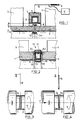
- les figures 3 et 4 représentent schématiquement une vue partielle schématique de la machine représentée sur la figure 2, montrant deux étapes du procédé correspondant de soudage par friction conforme à l'invention.
- Figure 1 shows a partial schematic view of a friction welding machine equipped with an induction heating means, according to a first embodiment of the invention;
- 2 shows a partial schematic view similar to that of Figure 1, of a welding machine by friction equipped with an induction heating means, according to a second embodiment of the invention;
- Figures 3 and 4 schematically show a partial schematic view of the machine shown in Figure 2, showing two steps of the corresponding method of friction welding according to the invention.
Le principe du soudage par friction inertielle dont un exemple de mise en oeuvre est représenté sur la figure 1 est bien connu en soi. Deux parties 1 et 2 de pièce à souder sont maintenues au moyen des mors de serrage, respectivement 3 et 4 d'une machine à souder partiellement représentée sur la figure 1. Dans les applications particulièrement visées par l'invention aux pièces de moteurs aéronautiques, il s'agit habituellement de pièces tournantes de révolution telles que le soudage d'arbres ou de rotors en superalliages à base de nickel. Selon ce principe connu, la partie 2 de pièce est fixe, tandis que la partie de pièce 1 est entraînée en rotation, solidarisée au moyen d'un embrayage avec un volant d'inertie. La partie de pièce 1 est rapprochée de la partie de pièce 2 et lorsqu'elles entrent en contact, une force de pression F maintient le contact entre les deux surfaces S₁ et S₂ de pièce qui générent un échauffement par frottement, dissipant l'énergie cinétique initiale emmagasinée. Quand les pièces s'immobilisent, une déformation des surfaces S₁ et S₂ est obtenue et produit un bourrelet 1a et 2a de part et d'autre du plan de soudage et le soudage est achevé.The principle of inertial friction welding, an exemplary implementation of which is shown in FIG. 1, is well known in itself. Two
Selon un autre procédé, de mise en oeuvre analogue, dit de soudage par friction pilotée, le processus fait intervenir deux phases successives. Tout d'abord, la pièce tournante est entraînée en rotation à vitesse constante par un moteur et frotte sur la pièce fixe sous l'effet d'une pression axiale modérée, provoquant ainsi un échauffement progressif. Lorsque l'échauffement est suffisant, un effort axial accru est appliqué pendant une durée déterminée, ce qui provoque un forgeage des pièces et la création de bourrelets par déformation, réalisant également le soudage.According to another method, of similar implementation, called piloted friction welding, the process involves two successive phases. First, the rotating part is driven in rotation at constant speed by a motor and rubs on the fixed part under the effect of moderate axial pressure, thus causing progressive heating. When the heating is sufficient, an increased axial force is applied for a determined period, which causes forging of the parts and the creation of beads by deformation, also carrying out the welding.
De manière remarquable et conforme à l'invention, lesdits procédés de soudage par friction sont modifiés par l'adjonction d'un apport thermique complémentaire effectué dans la zone des parties de pièce à souder en utilisant un moyen de chauffage par induction. Pour la mise en oeuvre de ce procédé modifié, conforme à l'invention, une machine à souder est équipée selon un premier mode de réalisation représenté sur la figure 1. Ladite machine comporte un inducteur constitué d'une spire unique 5 dont la cavité interne 6 est refroidie par circulation d'eau. Ladite spire 5 est recouverte d'une culasse magnétique 7 et sur sa face interne d'un revêtement 8 ayant des propriétés d'isolation, à la fois électrique et thermique.Remarkably and in accordance with the invention, said friction welding methods are modified by the addition of an additional thermal contribution made in the region of the parts of the workpiece to be welded using an induction heating means. For the implementation of this modified process, in accordance with the invention, a welding machine is equipped according to a first embodiment shown in FIG. 1. Said machine comprises an inductor consisting of a
Cet inducteur enveloppe les parties de pièce à souder et peut être prévu en deux parties pour faciliter les montages/démontages. L'inducteur comporte des points de fixation à la machine qui le relient notamment à un coulisseau symbolisé en 9 qui permet la mise en place précise par rapport aux pièces à souder, un jeu j suffisant étant en outre ménagé entre le diamètre interne de l'inducteur et les pièces pour permettre aux bourrelets 1a et 2a de se former sans entrer en contact avec l'inducteur.This inductor envelops the parts of the part to be welded and can be provided in two parts to facilitate assembly / disassembly. The inductor has attachment points to the machine which in particular connect it to a slide symbolized at 9 which allows precise positioning relative to the parts to be welded, a sufficient clearance j being furthermore provided between the internal diameter of the inductor and parts to allow the
L'alimentation en courant de l'inducteur est assurée par des conducteurs rigides 10. Un système de régulation symbolisé en 11, prenant en compte la température de la pièce dans la zone de soudage, permet de contrôler la puissance débitée par le générateur de courant alimentant l'inducteur de manière à piloter le cycle thermique de la zone soudée. L'apport thermique en fonction des applications particulières et des mises au point effectuées en fonction des résultats peut intervenir pendant tout ou partie du cycle de soudage, l'inducteur étant mis en place avant le soudage.
La maitrise du cycle thermique dans les zones soudées de pièce assurée par le pilotage de l'apport thermique grâce au premier mode de réalisation représenté schématiquement sur la figure 1 procure une amélioration notable des résultats. En effet, du point de vue métallurgique, dans les applications aux superalliages à durcissement structural, notamment à base de nickel pour pièces de moteurs aéronautiques, les microstructures précédemment obtenues dans les zones soudées ne sont pas satisfaisantes. On observe en effet une mise en solution des phases durcissantes de l'alliage par suite d'un échauffement local bref et important, suivie d'une reprécipitation fine lors du refroidissement. Les microstructures ainsi obtenues conduisent à des propriétés mécaniques, notamment les résistances à la propagation de fissures en fatigue ou au fluage, qui sont insuffisantes et nettement détériorées par rapport au matériau de base dans les zones non affectées.
L'application particulière suivante de l'invention permet, sur un superalliage à base de nickel à forte proportion de phase durcissante, de régénérer partiellement ou presque totalement la microstructure du métal de base et les caractéristiques mécaniques, en particulier la tenue à la propagation des fissures à chaud.
A la fin de l'opération de soudage, au lieu de laisser, suivant la pratique actuelle, la liaison se refroidir naturellement à partir de sa température d'environ 1250 - 1300°C, le moyen de chauffage est mis en oeuvre pour maintenir la liaison à une température comprise entre 100 et 1150°C, et cela pendant un temps qui peut varier de 15 à 60 minutes. A la fin de ce maintien la température est réduite suivant une loi programmée conduisant à des vitesses de refroidissement, entre 1100 et 700°C, comprises entre 100 et 200°C/min.
Ce palier à 110- 1150°C permet de régénérer une population de précipités durcissantes aux joints de grains de la zone de liaison et le refroidissement contrôlé permet de développer une précipitation durcissante intergranulaire correspondante à celle du métal de base.
La tenue à la propagation de fissure à chaud (vers 600- 700°C) qui sur une soudure faite de façon conventionnelle ne représente qu'une fraction infime de celle du métal de base : enrivon 1,5 %, est ramenée sensiblement au niveau de celle du métal de base.
Un refroidissement trop rapide de la zone de liaison introduit également des contraintes résiduelles de traction défavorables. Tous ces inconvénients sont supprimés, ou du moins sensiblement atténués grâce à la maîtrise obtenue du cycle thermique de l'opération de soudage par friction.
Outre ces avantages importants de qualité des résultats obtenus, l'invention peut également apporter un autre avantage notable. En effet, dans les applications où d'importantes énergies sont mises en jeu, la solution proposée d'apport thermique complémentaire grâce à un moyen de chauffage par induction constitue un moyen techniquement intéressant et moins coûteux d'accroître les capacités de la machine à souder. En effet, dans le cas d'un soudage par friction inertielle, les masses inertielles de la machine nécessaires peuvent être réduites et dans le cas d'un soudage par friction pilotée, la puissance du moteur d'entraînement peut être réduite pour tenir compte du préchauffage des parties de pièce à souder obtenu grâce au chauffage par induction. Ainsi, pour une puissance installée donnée de machine - masses inertielles ou moteur d'entraînement - les capacités se trouvent accrues par rapport aux machines classiques.The inductor is supplied with current by
The control of the thermal cycle in the welded areas of the part ensured by the control of the thermal contribution thanks to the first embodiment shown schematically in Figure 1 provides a significant improvement in the results. Indeed, from the metallurgical point of view, in applications to superalloys with structural hardening, in particular based on nickel for parts of aeronautical engines, the microstructures previously obtained in the welded zones are not satisfactory. There is indeed a dissolution of the hardening phases of the alloy as a result of brief and significant local heating, followed by fine reprecipitation during cooling. The microstructures thus obtained lead to mechanical properties, in particular the resistances to the propagation of cracks in fatigue or creep, which are insufficient and clearly deteriorated compared to the base material in the unaffected areas.
The following particular application of the invention makes it possible, on a nickel-based superalloy with a high proportion of hardening phase, to partially or almost completely regenerate the microstructure of the base metal and the mechanical characteristics, in particular the resistance to propagation of hot cracks.
At the end of the welding operation, instead of allowing, according to current practice, the connection to cool naturally from its temperature of around 1250 - 1300 ° C, the heating means is used to maintain the bond at a temperature between 100 and 1150 ° C, and this for a time which can vary from 15 to 60 minutes. At the end of this maintenance, the temperature is reduced according to a programmed law leading to cooling rates, between 1100 and 700 ° C, between 100 and 200 ° C / min.
This plateau at 110-1150 ° C. makes it possible to regenerate a population of hardening precipitates at the grain boundaries of the bonding zone and the controlled cooling makes it possible to develop an intergranular hardening precipitation corresponding to that of the base metal.
The resistance to hot crack propagation (around 600-700 ° C) which on a weld made in a conventional manner represents only a tiny fraction of that of the base metal: 1.5% coating, is reduced substantially to the level of that of the base metal.
Too rapid cooling of the connection zone also introduces unfavorable residual tensile stresses. All these drawbacks are eliminated, or at least substantially reduced, thanks to the control obtained from the thermal cycle of the friction welding operation.
In addition to these significant quality advantages of the results obtained, the invention can also provide another significant advantage. Indeed, in applications where large energies are involved, the proposed solution of additional heat input through an induction heating means constitutes a technically advantageous and less expensive means of increasing the capacities of the welding machine. . Indeed, in the case of inertial friction welding, the inertial masses of the machine required can be reduced and in the case of piloted friction welding, the power of the drive motor can be reduced to take account of the preheating of the parts to be welded obtained by induction heating. Thus, for a given installed power of machine - inertial masses or drive motor - the capacities are increased compared to conventional machines.
L'application particulière suivante illustre les avantages du procédé par un exemple de mise en oeuvre.The following particular application illustrates the advantages of the method by an example of implementation.
Une machine de soudage par friction inertielle donnée de capacité énergétique limitée à 3.10⁵ joules sera incapable de souder des pièces en superalliage de nickel à curcissement structural dont la surface à souder est supérieure à 4.10³mm². Le préchauffage des pièces, juste avant la mise en pression des deux pièces, suivant la procédure schématisée à la figure 1, à une température comprise entre 600 et 800°C pendant un temps varient de 1 à 5 Mn permet, en appliquant ensuite la procédure conventionnelle de soudage, de souder des surfaces pouvant atteindre 5.10³mm³, ce qui démontre un accroissement notable des capacités.A given inertial friction welding machine with an energy capacity limited to 3.10 joules will be unable to weld parts in nickel superalloy with structural hardening whose surface to be welded is greater than 4.10³mm². The preheating of the parts, just before the pressurization of the two parts, according to the procedure shown schematically in Figure 1, at a temperature between 600 and 800 ° C for a time vary from 1 to 5 Mn allows, then applying the procedure conventional welding, welding surfaces up to 5.10³mm³, which demonstrates a significant increase in capacity.
En fonction des applications particulières ou du type de machine à souder par friction utilisée, l'invention peut donner lieu à diverses variantes de réalisation. Un deuxième mode de réalisation est notamment représenté sur la figure 2, à titre d'exemple. On retrouve les éléments analogues de la machine à souder pour lesquels les mêmes repères de référence ont été conservés : deux parties 1 et 2 de pièce à souder sont maintenues au moyen de mors de serrage 3 et 4. Dans ce cas, entre les deux surfaces de pièce en regard S₁ et s₂ destinées à être soudées, on dispose un inducteur plat 12. L'inducteur 12 comporte un circuit d'induction 13 monospire dont la cavité interne 14 est refroidie par circulation d'eau et la spire 13 est entourée d'une culasse magnétique extérieure 15 et d'une culasse magnétique intérieure 16 et latéralement, sur chaque côté, sa face est recouverte d'un revêtement 17 et 18 possédant des propriétés d'isolation à la fois électrique et thermique. Les figures 3 et 4 schématisent le fonctionnement dans le procédé de soudage par friction. Lors de l'étape de mise en rotation de l'une des parties de pièce à souder, 2 par exemple dans le mode représenté sur la figure 3, le chauffage au moyen de l'inducteur 12 est enclenché et maintenu jusqu'à obtenir la température désirée de préchauffage des zones à souder. Le chauffage est alors interrompu et l'inducteur 12 est rapidement escamoté au moyen d'un bras-support 19 solidaire de la machine. Les deux parties 1 et 2 de pièce sont alors rapprochées en appliquant une force de pression F jusqu'à immobilisation de la pièce tournante et réalisation du soudage. On observe comme précédemment les bourrelets 1a et 2a de soudage, comme représenté sur la figure 4.Depending on the particular applications or the type of friction welding machine used, the invention can give rise to various variant embodiments. A second embodiment is notably shown in FIG. 2, by way of example. We find similar elements of the welding machine for which the same reference marks have been kept: two
Les résultats et avantages précédemment notés sont également obtenus dans ce deuxième mode de réalisation de l'invention. Pour assurer la maîtrise du cycle de chauffage, comme précédemment, l'inducteur 12 est associé à un système de régulation, de définition connu en soi, prenant en compte une mesure de température de la zone de soudage de la pièce et pilotant la source de chauffage alimentant l'inducteur.The previously noted results and advantages are also obtained in this second embodiment of the invention. To ensure control of the heating cycle, as previously, the
Claims (8)
Applications Claiming Priority (2)
| Application Number | Priority Date | Filing Date | Title |
|---|---|---|---|
| FR9002618 | 1990-03-02 | ||
| FR9002618A FR2659038B1 (en) | 1990-03-02 | 1990-03-02 | FRICTION WELDING PROCESS AND IMPLEMENTATION MACHINE. |
Publications (2)
| Publication Number | Publication Date |
|---|---|
| EP0445035A1 true EP0445035A1 (en) | 1991-09-04 |
| EP0445035B1 EP0445035B1 (en) | 1994-06-01 |
Family
ID=9394308
Family Applications (1)
| Application Number | Title | Priority Date | Filing Date |
|---|---|---|---|
| EP91400543A Expired - Lifetime EP0445035B1 (en) | 1990-03-02 | 1991-02-28 | Friction welding method |
Country Status (5)
| Country | Link |
|---|---|
| US (1) | US5240167A (en) |
| EP (1) | EP0445035B1 (en) |
| JP (1) | JPH07112631B2 (en) |
| DE (1) | DE69102165T2 (en) |
| FR (1) | FR2659038B1 (en) |
Cited By (7)
| Publication number | Priority date | Publication date | Assignee | Title |
|---|---|---|---|---|
| DE4135882A1 (en) * | 1991-10-31 | 1993-05-06 | Kuka Schweissanlagen + Roboter Gmbh, 8900 Augsburg, De | Welding process - by heating parts to be joined at welding seam and forging together with force using preset welding process parameters |
| WO1993013908A1 (en) * | 1992-01-14 | 1993-07-22 | Ball Burnishing Machine Tools Limited | Galled joints made with electric heating |
| EP0937531A3 (en) * | 1998-02-23 | 2000-10-18 | Mtu Motoren- Und Turbinen-Union MàNchen Gmbh | Friction welding method for fixing blades onto a rotor of a steam machine |
| RU2158663C1 (en) * | 1999-09-07 | 2000-11-10 | Оао "Компат" | Device to provided impulse induction welding along flanged edges |
| WO2011012906A1 (en) * | 2009-07-30 | 2011-02-03 | The University Of Wolverhampton | Heating apparatus and method |
| US7882998B2 (en) | 2005-09-26 | 2011-02-08 | Helmholtz-Zentrum Geesthacht Zentrum für Material-und Küstenforschung GmbH | Method and apparatus of producing a welded connection between the surfaces of two planar workpieces |
| DE102016217024A1 (en) * | 2016-09-07 | 2018-03-08 | Mahle International Gmbh | Manufacturing process of a camshaft |
Families Citing this family (43)
| Publication number | Priority date | Publication date | Assignee | Title |
|---|---|---|---|---|
| SE506294C2 (en) * | 1993-06-11 | 1997-12-01 | Volvo Ab | Device for joining two work pieces made of sheet metal |
| US5431325A (en) * | 1993-12-27 | 1995-07-11 | Ford Motor Company | Method and apparatus for producing hermetic torque converter seam |
| US5831252A (en) * | 1995-02-08 | 1998-11-03 | Daido Tokushuko Kabushiki Kaisha | Methods of bonding titanium and titanium alloy members by high frequency heating |
| US6516992B1 (en) * | 1996-05-31 | 2003-02-11 | The Boeing Company | Friction stir welding with simultaneous cooling |
| SE9701265D0 (en) * | 1997-04-04 | 1997-04-04 | Esab Ab | Method and apparatus for friction stir welding |
| US6138896A (en) * | 1998-10-05 | 2000-10-31 | General Electric Company | Superspeed inertia welding |
| DE69920770T2 (en) * | 1998-11-02 | 2005-10-06 | Spinduction Weld, Inc. | Improved process for solid-state welding and welded workpieces |
| DE29922396U1 (en) * | 1999-12-20 | 2000-11-09 | KUKA Schweissanlagen GmbH, 86165 Augsburg | Pressure welding device |
| US6333484B1 (en) * | 2000-03-17 | 2001-12-25 | Chromalloy Gas Turbine Corporation | Welding superalloy articles |
| GB2368550B (en) * | 2000-09-07 | 2004-09-01 | Rolls Royce Plc | Method and apparatus for friction welding |
| US6691910B2 (en) * | 2000-12-08 | 2004-02-17 | Fuji Oozx, Inc. | Method of joining different metal materials by friction welding |
| US6776328B2 (en) * | 2002-09-17 | 2004-08-17 | The Boeing Company | Radiation assisted friction welding |
| ITTO20021002A1 (en) * | 2002-11-15 | 2004-05-16 | Fiat Ricerche | TANK FOR STORAGE OF HIGH PRESSURE FLUIDS, |
| US20040099714A1 (en) * | 2002-11-26 | 2004-05-27 | Strusinski Thaddeus J. | Reduced weldment pre-heat technique for nickel based superalloys |
| AU2003238525A1 (en) * | 2003-05-14 | 2004-12-03 | Alstom Technology Ltd | Method for welding together structural components and rotor produced according to said method |
| US8266800B2 (en) * | 2003-09-10 | 2012-09-18 | Siemens Energy, Inc. | Repair of nickel-based alloy turbine disk |
| US6913186B2 (en) * | 2003-09-11 | 2005-07-05 | The Boeing Company | Apparatus and method for friction stir welding with a variable speed pin |
| US6994242B2 (en) * | 2003-12-09 | 2006-02-07 | The Boeing Company | Friction stir weld tool and method |
| US20070175967A1 (en) * | 2006-01-27 | 2007-08-02 | Narasimha-Rao Venkata Bangaru | High integrity welding and repair of metal components |
| US8141768B2 (en) * | 2006-01-27 | 2012-03-27 | Exxonmobil Research And Engineering Company | Application of high integrity welding and repair of metal components in oil and gas exploration, production and refining |
| US20080237304A1 (en) * | 2007-03-30 | 2008-10-02 | Caterpillar Inc. | Engine component having friction welded inserts |
| GB0712225D0 (en) * | 2007-06-23 | 2007-08-01 | Rolls Royce Plc | Welding enclosure |
| US8356980B2 (en) | 2007-10-09 | 2013-01-22 | Hamilton Sundstrand Corporation | Method of manufacturing a turbine rotor |
| US20090185908A1 (en) * | 2008-01-21 | 2009-07-23 | Honeywell International, Inc. | Linear friction welded blisk and method of fabrication |
| MX2010010191A (en) * | 2008-03-28 | 2010-10-08 | Shawcor Ltd | Demagnetization system and method. |
| JP5243083B2 (en) * | 2008-04-01 | 2013-07-24 | 株式会社豊田自動織機 | Friction welding method |
| DE102008037747A1 (en) * | 2008-08-14 | 2010-02-18 | Märkisches Werk GmbH | bimetal |
| DE102010005263A1 (en) * | 2010-01-20 | 2011-07-21 | Benteler Automobiltechnik GmbH, 33102 | Method for manufacturing component for mounting towing eye, involves warming component region at specific temperature and mechanically deforming component region |
| JP5853405B2 (en) * | 2011-04-25 | 2016-02-09 | 株式会社Ihi | Friction welding method and bonded structure |
| US9347124B2 (en) * | 2011-11-07 | 2016-05-24 | Siemens Energy, Inc. | Hold and cool process for superalloy joining |
| US9644769B1 (en) | 2013-03-20 | 2017-05-09 | Paul Po Cheng | System and method for welding tubular workpieces |
| CN104379269B (en) | 2013-04-11 | 2017-04-12 | 株式会社富士工 | Method for producing rolling roll, rolling roll, and device for producing rolling roll |
| US10288193B2 (en) | 2017-01-25 | 2019-05-14 | Paul Po Cheng | Method and system for forming a pipeline |
| DE102017212885A1 (en) * | 2017-07-26 | 2019-01-31 | Mahle International Gmbh | Manufacturing method of a valve |
| KR102086914B1 (en) * | 2018-08-14 | 2020-04-23 | 부경대학교 산학협력단 | Electric resistance line welding machine and electric resistance spot welding machine of overlapped metallic sheets with induction heating and surface rotational friction heating |
| US11577295B2 (en) * | 2019-04-03 | 2023-02-14 | Paul Po Cheng | System and method for connecting metal workpieces |
| US11413699B2 (en) | 2019-08-21 | 2022-08-16 | Paul Po Cheng | Method and system for fusing pipe segments |
| US12275093B2 (en) * | 2020-03-17 | 2025-04-15 | Paul Po Cheng | Method for attaching a tube to a workpiece |
| US12251772B2 (en) * | 2020-03-17 | 2025-03-18 | Paul Po Cheng | Method for solid state welding |
| US11597032B2 (en) | 2020-03-17 | 2023-03-07 | Paul Po Cheng | Method and system for modifying metal objects |
| US20240316689A1 (en) * | 2021-08-19 | 2024-09-26 | Osaka University | Solid-state joining method, solid-state joined joint, solid-state joined structure, and solid-state joining device |
| WO2023144628A1 (en) * | 2022-01-31 | 2023-08-03 | Spinduction Weld Inc. | Parallel robotics system and method of induction kinetic hybrid welding processes |
| US20250128347A1 (en) * | 2023-10-20 | 2025-04-24 | Electric Power Research Institute, Inc. | Methodology to manufacture a monolithic vessel head with integral tube attachments via solid-state joining |
Citations (4)
| Publication number | Priority date | Publication date | Assignee | Title |
|---|---|---|---|---|
| DE1177756B (en) * | 1963-04-20 | 1964-09-10 | Deutsche Edelstahlwerke Ag | Method and device for preheating the end surfaces of workpieces for the purposes of the subsequent butt welding in the immediate passage of current |
| GB982337A (en) * | 1961-11-22 | 1965-02-03 | Ohio Crankshaft Co | Improvements in or relating to pipe seam welding apparatus |
| FR2107474A5 (en) * | 1970-09-25 | 1972-05-05 | Zentralinstitut Schweiss | Combined friction - and resistance welding process - for joining thin metal strip |
| FR2299940A1 (en) * | 1975-02-04 | 1976-09-03 | Mitsubishi Heavy Ind Ltd | Bonding metallic bodies using insert - which forms reducing atmos. preventing oxide formation |
Family Cites Families (10)
| Publication number | Priority date | Publication date | Assignee | Title |
|---|---|---|---|---|
| US2676233A (en) * | 1950-11-29 | 1954-04-20 | Republic Steel Corp | Single turn induction coil |
| US2919335A (en) * | 1958-03-31 | 1959-12-29 | Cons Edison Co New York Inc | Induction welding of metallic pipes |
| GB1299745A (en) * | 1970-04-17 | 1972-12-13 | Welders Ltd A I | Improvements in or relating to friction welding |
| JPS5248782B2 (en) * | 1972-04-22 | 1977-12-12 | ||
| JPS5721434A (en) * | 1980-07-14 | 1982-02-04 | Shin Etsu Chem Co Ltd | Surface treatment of vinyl chloride resin molded article |
| JPS6144391U (en) * | 1984-08-27 | 1986-03-24 | 三菱重工業株式会社 | marine propeller |
| US4698473A (en) * | 1986-05-02 | 1987-10-06 | General Motors Corporation | Refractory metal-lined induction coil |
| US4717801A (en) * | 1986-08-11 | 1988-01-05 | Fmc Corporation | Dual induction heating pressure welding apparatus having a control circuit |
| JPS6429039A (en) * | 1987-07-23 | 1989-01-31 | Fuji Xerox Co Ltd | Data transmission reception controller |
| FR2641222B1 (en) * | 1989-01-04 | 1994-06-03 | Snecma | INERTIAL FRICTION WELDING PROCESS |
-
1990
- 1990-03-02 FR FR9002618A patent/FR2659038B1/en not_active Expired - Fee Related
-
1991
- 1991-02-28 DE DE69102165T patent/DE69102165T2/en not_active Expired - Fee Related
- 1991-02-28 EP EP91400543A patent/EP0445035B1/en not_active Expired - Lifetime
- 1991-03-01 US US07/663,022 patent/US5240167A/en not_active Expired - Lifetime
- 1991-03-01 JP JP3059521A patent/JPH07112631B2/en not_active Expired - Fee Related
Patent Citations (4)
| Publication number | Priority date | Publication date | Assignee | Title |
|---|---|---|---|---|
| GB982337A (en) * | 1961-11-22 | 1965-02-03 | Ohio Crankshaft Co | Improvements in or relating to pipe seam welding apparatus |
| DE1177756B (en) * | 1963-04-20 | 1964-09-10 | Deutsche Edelstahlwerke Ag | Method and device for preheating the end surfaces of workpieces for the purposes of the subsequent butt welding in the immediate passage of current |
| FR2107474A5 (en) * | 1970-09-25 | 1972-05-05 | Zentralinstitut Schweiss | Combined friction - and resistance welding process - for joining thin metal strip |
| FR2299940A1 (en) * | 1975-02-04 | 1976-09-03 | Mitsubishi Heavy Ind Ltd | Bonding metallic bodies using insert - which forms reducing atmos. preventing oxide formation |
Cited By (10)
| Publication number | Priority date | Publication date | Assignee | Title |
|---|---|---|---|---|
| DE4135882A1 (en) * | 1991-10-31 | 1993-05-06 | Kuka Schweissanlagen + Roboter Gmbh, 8900 Augsburg, De | Welding process - by heating parts to be joined at welding seam and forging together with force using preset welding process parameters |
| DE4135882C2 (en) * | 1991-10-31 | 2001-04-19 | Kuka Schweissanlagen Gmbh | Method, use and device for welding components |
| WO1993013908A1 (en) * | 1992-01-14 | 1993-07-22 | Ball Burnishing Machine Tools Limited | Galled joints made with electric heating |
| EP0937531A3 (en) * | 1998-02-23 | 2000-10-18 | Mtu Motoren- Und Turbinen-Union MàNchen Gmbh | Friction welding method for fixing blades onto a rotor of a steam machine |
| RU2158663C1 (en) * | 1999-09-07 | 2000-11-10 | Оао "Компат" | Device to provided impulse induction welding along flanged edges |
| US7882998B2 (en) | 2005-09-26 | 2011-02-08 | Helmholtz-Zentrum Geesthacht Zentrum für Material-und Küstenforschung GmbH | Method and apparatus of producing a welded connection between the surfaces of two planar workpieces |
| WO2011012906A1 (en) * | 2009-07-30 | 2011-02-03 | The University Of Wolverhampton | Heating apparatus and method |
| GB2485323A (en) * | 2009-07-30 | 2012-05-09 | Univ Wolverhampton | Heating apparatus and method |
| GB2485323B (en) * | 2009-07-30 | 2015-05-27 | Univ Derby | Heating apparatus and method |
| DE102016217024A1 (en) * | 2016-09-07 | 2018-03-08 | Mahle International Gmbh | Manufacturing process of a camshaft |
Also Published As
| Publication number | Publication date |
|---|---|
| FR2659038A1 (en) | 1991-09-06 |
| JPH07112631B2 (en) | 1995-12-06 |
| DE69102165D1 (en) | 1994-07-07 |
| FR2659038B1 (en) | 1994-11-10 |
| EP0445035B1 (en) | 1994-06-01 |
| US5240167A (en) | 1993-08-31 |
| JPH04224087A (en) | 1992-08-13 |
| DE69102165T2 (en) | 1994-11-17 |
Similar Documents
| Publication | Publication Date | Title |
|---|---|---|
| EP0445035B1 (en) | Friction welding method | |
| US10718041B2 (en) | Solid-state welding of coarse grain powder metallurgy nickel-based superalloys | |
| US20130064672A1 (en) | Method of manufacturing a turbine rotor | |
| US20100102106A1 (en) | Welding enclosure | |
| EP2760616B1 (en) | Build up welding method for metal pieces of aluminium by pulsed current and pulsed welding material feeding mig welding | |
| CA2889321A1 (en) | Local heat treatment and thermal management system for engine components | |
| CA3004391C (en) | Device for generating a structural-gradient microstructure on an axisymmetric part | |
| US20140120483A1 (en) | Local Heat Treatment and Thermal Management System for Engine Components | |
| JP2011101897A (en) | Poppet valve seat of which is built up and method of manufacturing it | |
| FR2921284A1 (en) | PROCESS FOR RECOVERING TURBOMACHINE ELEMENTS | |
| FR2923741A1 (en) | Repairing thermomechanical component e.g. turbomachine blade using high energy beam e.g. electron/laser beam, by replacing damaged portion of component with another portion such as inlay, and performing heat treatment at junction zone | |
| CN116043003A (en) | A Friction Extrusion Strengthening Method for Inertial Friction Welding Engine Blisk Welds | |
| BE897556A (en) | DIFFERENTIAL PRESSURE METHOD AND APPARATUS FOR JOINING A SLEEVE AND A TUBE | |
| WO2026033172A1 (en) | Welding method for a motor vehicle body | |
| FR2531890A1 (en) | METHOD AND APPARATUS WITH DIFFERENTIAL PRESSURE FOR ASSEMBLING A SLEEVE AND A TUBE | |
| FR2678195A1 (en) | PROCESS FOR THE INDUCTIVE TREATMENT OF METAL PARTS, PARTICULARLY STEEL, CRACKED OR SUSCEPTIBLE OF BEING. | |
| EP0955452A1 (en) | Process for fitting a valve seat in an engine cylinder head | |
| JP2536630B2 (en) | Method for joining ceramic member and metal member | |
| JPWO2006117847A1 (en) | Micro gas turbine | |
| FR3101560A1 (en) | RECHARGING PROCESS FOR A METAL TURBOMACHINE PART | |
| FR3050020A1 (en) | THERMAL EXCHANGER AND METHOD OF MANUFACTURING A HEAT EXCHANGER | |
| EP3921113A1 (en) | Method for separating a first mechanical part from a second mechanical part | |
| FR3003491A1 (en) | WELDING OF ALUMINUM LEAVES BY BOSSAGE. | |
| WO2024252087A1 (en) | Method for the heat treatment of a bi-material metal part and device for carrying out the method | |
| FR2999967A1 (en) | Method for fixing skirt on turbine shaft of hydraulic machinery, involves moving metal part into zone at another zone of another metal part to fix former metal part on former zone of latter metal part |
Legal Events
| Date | Code | Title | Description |
|---|---|---|---|
| PUAI | Public reference made under article 153(3) epc to a published international application that has entered the european phase |
Free format text: ORIGINAL CODE: 0009012 |
|
| 17P | Request for examination filed |
Effective date: 19910318 |
|
| AK | Designated contracting states |
Kind code of ref document: A1 Designated state(s): DE FR GB |
|
| 17Q | First examination report despatched |
Effective date: 19921028 |
|
| GRAA | (expected) grant |
Free format text: ORIGINAL CODE: 0009210 |
|
| AK | Designated contracting states |
Kind code of ref document: B1 Designated state(s): DE FR GB |
|
| GBT | Gb: translation of ep patent filed (gb section 77(6)(a)/1977) |
Effective date: 19940608 |
|
| REF | Corresponds to: |
Ref document number: 69102165 Country of ref document: DE Date of ref document: 19940707 |
|
| PLBE | No opposition filed within time limit |
Free format text: ORIGINAL CODE: 0009261 |
|
| STAA | Information on the status of an ep patent application or granted ep patent |
Free format text: STATUS: NO OPPOSITION FILED WITHIN TIME LIMIT |
|
| 26N | No opposition filed | ||
| REG | Reference to a national code |
Ref country code: GB Ref legal event code: IF02 |
|
| REG | Reference to a national code |
Ref country code: FR Ref legal event code: TP Ref country code: FR Ref legal event code: CD |
|
| PGFP | Annual fee paid to national office [announced via postgrant information from national office to epo] |
Ref country code: DE Payment date: 20060125 Year of fee payment: 16 |
|
| PGFP | Annual fee paid to national office [announced via postgrant information from national office to epo] |
Ref country code: GB Payment date: 20060126 Year of fee payment: 16 |
|
| PGFP | Annual fee paid to national office [announced via postgrant information from national office to epo] |
Ref country code: FR Payment date: 20060127 Year of fee payment: 16 |
|
| REG | Reference to a national code |
Ref country code: FR Ref legal event code: CD |
|
| GBPC | Gb: european patent ceased through non-payment of renewal fee |
Effective date: 20070228 |
|
| REG | Reference to a national code |
Ref country code: FR Ref legal event code: ST Effective date: 20071030 |
|
| PG25 | Lapsed in a contracting state [announced via postgrant information from national office to epo] |
Ref country code: DE Free format text: LAPSE BECAUSE OF NON-PAYMENT OF DUE FEES Effective date: 20070901 |
|
| PG25 | Lapsed in a contracting state [announced via postgrant information from national office to epo] |
Ref country code: FR Free format text: LAPSE BECAUSE OF NON-PAYMENT OF DUE FEES Effective date: 20070228 Ref country code: GB Free format text: LAPSE BECAUSE OF NON-PAYMENT OF DUE FEES Effective date: 20070228 |