EP0445028B1 - Kopplungsvorrichtung für mindestens zwei Sender und Empfänger mit einer gemeinsamen Antenne - Google Patents
Kopplungsvorrichtung für mindestens zwei Sender und Empfänger mit einer gemeinsamen Antenne Download PDFInfo
- Publication number
- EP0445028B1 EP0445028B1 EP91400530A EP91400530A EP0445028B1 EP 0445028 B1 EP0445028 B1 EP 0445028B1 EP 91400530 A EP91400530 A EP 91400530A EP 91400530 A EP91400530 A EP 91400530A EP 0445028 B1 EP0445028 B1 EP 0445028B1
- Authority
- EP
- European Patent Office
- Prior art keywords
- antenna
- receiver
- transmitter
- coupling
- circuit
- Prior art date
- Legal status (The legal status is an assumption and is not a legal conclusion. Google has not performed a legal analysis and makes no representation as to the accuracy of the status listed.)
- Expired - Lifetime
Links
- 230000008878 coupling Effects 0.000 title claims description 41
- 238000010168 coupling process Methods 0.000 title claims description 41
- 238000005859 coupling reaction Methods 0.000 title claims description 41
- 230000008054 signal transmission Effects 0.000 claims 2
- 230000005540 biological transmission Effects 0.000 description 25
- 101100536250 Homo sapiens TMEM120A gene Proteins 0.000 description 11
- 102100028548 Ion channel TACAN Human genes 0.000 description 11
- 238000010586 diagram Methods 0.000 description 7
- 239000012212 insulator Substances 0.000 description 4
- 230000035945 sensitivity Effects 0.000 description 4
- 230000002238 attenuated effect Effects 0.000 description 3
- 238000009434 installation Methods 0.000 description 3
- 238000005259 measurement Methods 0.000 description 3
- 230000005855 radiation Effects 0.000 description 3
- 230000009467 reduction Effects 0.000 description 3
- 230000006378 damage Effects 0.000 description 2
- 238000011144 upstream manufacturing Methods 0.000 description 2
- 230000015556 catabolic process Effects 0.000 description 1
- 238000006731 degradation reaction Methods 0.000 description 1
- 238000003745 diagnosis Methods 0.000 description 1
- 230000005670 electromagnetic radiation Effects 0.000 description 1
- 238000005516 engineering process Methods 0.000 description 1
- 235000021183 entrée Nutrition 0.000 description 1
- 238000002513 implantation Methods 0.000 description 1
- 230000003993 interaction Effects 0.000 description 1
- 239000000463 material Substances 0.000 description 1
- 230000021715 photosynthesis, light harvesting Effects 0.000 description 1
- 238000000926 separation method Methods 0.000 description 1
- 238000006467 substitution reaction Methods 0.000 description 1
Images


Classifications
-
- H—ELECTRICITY
- H01—ELECTRIC ELEMENTS
- H01P—WAVEGUIDES; RESONATORS, LINES, OR OTHER DEVICES OF THE WAVEGUIDE TYPE
- H01P1/00—Auxiliary devices
- H01P1/20—Frequency-selective devices, e.g. filters
- H01P1/213—Frequency-selective devices, e.g. filters combining or separating two or more different frequencies
Definitions
- the present invention relates to a device for coupling to a common antenna of at least two devices transmitting and / or receiving microwave signals operating in the same frequency range but having separate useful bands.
- the location of the antennas must be optimized in order to meet given directivity criteria.
- the presence of several transmitting or receiving antennas in the same range or frequency band can give rise to undesirable couplings between the different devices. These couplings strongly depend on the respective positions of the antennas on the airplane as well as on the shapes of the airplane.
- such a coupling device must guarantee a minimum of interaction between the two devices, improve or at least maintain the performance obtained with two separate radiating devices, have a minimum weight and offer a very high degree of reliability.
- the document JP-A-59 185 408 describes a device for coupling to a common antenna of several transmitting and receiving apparatuses of microwave signals operating in the same frequency range but having disjoint useful bands.
- each transmitter / receiver device is coupled to a circulator by means of two parallel bandpass filters connected respectively to the transmission and reception channels of the device.
- the various circulators associated with the respective devices are connected in series to a common circulator for coupling to the common antenna.
- the invention makes it possible to achieve the objectives, while overcoming the drawbacks presented by the device of document JP-A-59 185 408 thanks to the fact that the attenuation in each transmission and reception channel only depends on the total number of channels.
- the transmitter and the receiver of the first device have separate useful bands.
- said circuit comprises at least a third circulator having a first terminal intended to be connected to the transmitter and / or to the receiver of one of the devices, a second terminal connected to the connection path of said transmitter to the antenna and a third terminal connected to the connection path of said receiver to the antenna.
- the circuit can be completed by a fourth circulator connected similarly to the third circulator between the other device and the other two connection paths respectively.
- the first and fourth filters of each circuit then have a width of band encompassing the useful bands of all the transmitters connected to the first channel of this circuit, and said second and third filters of this same circuit have a bandwidth encompassing the useful bands of all of the receivers connected to the second track of this circuit.
- each circuit is connected to the following circuit on the antenna side by means of one of the aforementioned third and fourth circulators.
- each group of devices can be directly coupled to the antenna with at least one four-way circuit.
- an impedance adapter isolator is preferably connected between each filter and each adjacent circulator.
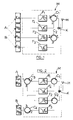
- Figure 1 is a diagram of a device according to a first embodiment for coupling to a common antenna of two transmitting and receiving devices.
- FIG. 2 is a diagram of a first alternative embodiment of the device of FIG. 1.
- Figure 3 is a view of the coupling device of Figure 2 further equipped with insulators.
- Figure 4 is a diagram of a device with two elementary circuits connected in series to ensure the coupling of three transmitting / receiving devices to a common antenna.
- FIG. 5 is a diagram of a device with two elementary circuits connected in parallel for the coupling of two pairs of transmitting and receiving apparatuses to a common antenna.
- FIG. 6 is a diagram of a device with two identical elementary circuits for the coupling of two transmitting / receiving devices with two common antennas.
- two transmitting / receiving apparatuses A and B are coupled to an antenna H by means of a coupling circuit M with four channels.
- the circuit M includes four passive filters F1, F2, F3, F4 and two circulators C1 and C2 connected to the antenna H via a coupler K.
- an ideal circulator is a three-terminal circuit in which the signals are transmitted in one direction between two adjacent terminals, but not in the opposite direction.
- the signals pass directly from terminal 1 to terminal 2, from terminal 2 to terminal 3, and from terminal 3 at terminal 1.
- the transmission is negligible in the opposite direction, namely from 1 to 3, from 3 to 2, and from 2 to 1.
- the direction of transmission of the circulators is indicated by an arrow.
- the emitter E A of the device A is coupled to the antenna H by a first channel comprising the passive filter F1 and the connection between the terminals 3 and 1 of the circulator C1.
- the filter F1 is a bandpass filter centered on the middle f EA of the useful band of the transmitter E A.
- the receiver R A of the device A is coupled to the antenna H by a second channel comprising the passive filter F2 and the connection between terminals 1 and 2 of the second circulator C2.
- the filter F2 is a bandpass filter centered on the middle f RA of the useful band of the receiver R A.
- the emitter E B of the second device B is coupled to the antenna H by a third channel comprising the passive filter F3 and the connection between terminals 3 and 1 of the second circulator C2.
- the passive filter F3 is a band rejection filter centered on the middle f RA of the useful band of the receiver R A of the first device A.
- the receiver R B of the device B is coupled to the antenna H by a fourth channel comprising the passive filter F4 and the link between terminals 1 and 2 of the first circulator C1.
- the filter F4 is a band rejection filter centered on the middle f EA of the useful band of the transmitter E A of the device A.
- the signals produced by the transmitter E A are transmitted to the antenna H with negligible attenuation via the filter F1 which attenuates the components of these signals located outside the useful band of the transmitter, the connection between terminals 3 and 1 of circulator C1 and coupler K.
- the receiver R B of device B is protected against the signals produced by the transmitter E A , on the one hand by the circulator C1 which introduces an attenuation of the order of - 20 dB between terminals 3 and 2, on the other hand by the band rejection filter F4 centered precisely on the middle of the useful band of the transmitter E A.
- the signals coming from the transmitter E A are also transmitted to the receiver R A via the coupler K and the pass-through link between the terminals 1 and 2 of the circulator C2.
- the antenna H picks up frequency signals located in the useful band of the receiver R A , they are transmitted to the latter with negligible attenuation via the coupler K, the circulator C2 and the passive filter F2.
- the relatively low energy level of the signals thus received is not likely to affect the transmitters E A and E B which, moreover, are protected by the circulator C1 and the bandpass filter F1 for the first and by the circulator C2 for the second.
- the receiver R B receives these signals with negligible attenuation via the coupler K, the circulator C1 and the filter F4, but by definition the receiver R B is not tuned to the reception frequency of the receiver R A and this coupling is therefore not troublesome.
- the transmitter E B When the transmitter E B transmits, it does so in one or more frequency bands which are separated from the useful bands of the transmitter E A and the receiver R A.
- the band rejector filter F3 strongly attenuates the components of these signals which are located in the useful band of the receiver R A.
- the signals located in the useful band or bands of the transmitter E B are therefore transmitted with negligible attenuation to the antenna H via the filters F3, the circulator C2 and the coupler K.
- the receiver R A is protected against this emission by the attenuations brought by the filter F3 in its useful band and by the link 3-2 of the circulator C2.
- the transmitter E A does not require any particular protection with respect to the transmissions of the transmitter E B since, as indicated previously, the transmitter E B does not transmit in its useful band and that, if it exists nevertheless of the components of the transmitted signals located in this band, they will be of a relatively low energy level and will be attenuated by the connection 1-3 of the circulator C1. Finally, there is no particular protection of the receiver R B with respect to the transmissions of the transmitter E B because the device B is supposed to be of the simplex type, so that it cannot transmit and receive simultaneously signals.
- the antenna H picks up frequency signals located in the useful band of the receiver R B , they are transmitted to the latter with negligible attenuation through the coupler K, the circulator C1 and the filter F4.
- the presence of the latter does not affect the reception of signals by the receiver R B since it has been seen previously that the useful band or bands of the latter are separated from the useful band of the transmitter E A on the middle of which is centered the rejector filter F4.
- the signals received by the antenna H in the useful band or bands of the receiver R B are not likely to affect the transmitters E A and E B.
- These low level signals are further attenuated by the reverse connection 1-3 of the circulators C1 and C2.
- the receiver R A is protected from these received signals, on the one hand by the filter F2 which lets through only the useful band of this receiver, on the other hand by the fact that the receiver R A is not tuned on the reception frequency (s) of the receiver R B.
- the circuit M which has just been described therefore makes it possible to couple to the same antenna two apparatuses A and B transmitters and / or receivers of microwave signals operating in the same frequency range but having disjoint useful bands.
- One of the devices, B must be simplex because the receiver R B is not protected from emissions from transmitter E B.
- the other device A can be duplex as described with reference to FIG. 1, the transmission and reception frequencies then being distinct.
- the apparatus A can be simplex and, in this case, the transmission and reception frequencies can be either distinct or identical.
- all the filters F1 to F4 are centered on the middle of the useful band of the transmitter and the receiver of the device A.
- FIG. 2 illustrates an alternative embodiment in which the circuit M is completed by a third circulator C3 and a fourth circulator C4.
- the circulator C3 has a first connection terminal to the device A, a second terminal connected to the filter F1 and a third terminal connected to the filter F2.
- the circulator C4 has a first connection terminal to the device B, a second terminal connected to the filter F3 and a third terminal connected to the filter F4.
- the circuit M of FIG. 2 is absolutely identical to that of FIG. 1.
- each of the circulators C3 and C4 ensures the transmission of the signals from the transmitter to the corresponding transmission channel via the link between terminals 1 and 2, and from the reception channel to the corresponding receiver by through the connection between terminals 3 and 1.
- the device B can also be duplex: it suffices to provide a conventional duplexer filter (not shown) between the device transceiver and the device (not shown) for coupling to terminal 1 of circulator C4.
- This second embodiment is also suitable for cascading or "series" mounting of several circuits M as will be explained below.
- microwave isolators I can be connected between each of the filters F1, F2, F3, F4 and the adjacent circulator C1, C2, C3, C4.
- These insulators I can each consist of a circulator connected in the desired direction by two of its terminals between a filter and an adjacent circulator and the third terminal of which is connected to a microwave energy dissipation load.
- circuit M it may include all of the insulators shown in Figure 3 or only a portion thereof.
- the circuit M which has just been described makes it possible to couple an identification responder (IFF, ATC) and a data transmission and / or distance measurement equipment to a common antenna of an aircraft. and possibly from a ground beacon (MIDS, TACAN, DME).
- IFF identification responder
- MIDS ground beacon
- TACAN TACAN
- DME ground beacon
- each of these two devices is coupled on a plane to a high antenna and a low antenna, but for the simplicity of the description a single antenna will be considered, it being understood that two identical circuits allow the coupling of the two devices to two antennas common as described in Figure 6.
- the IFF, ATC responder (device A) can be modeled by a generator at 1030 MHz of power 57 dBm (decibels / milliwatt) exciting the antenna and by a receiver at 1090 MHz of sensitivity - 74 dBm excited by the antenna.
- the set MIDS, TACAN, DME can be modeled by a power generator 53 dBm exciting the antenna and a sensitivity receiver - 60 dBm excited by the antenna, this transmitter (E B ) and this receiver ( R B ) operating in several useful bands located in the same microwave range (L band) as the IFF, ATC transponder, excluding the bands centered at 1030 and 1090 MHz.
- the filters F1 and F4 are centered on 1090 MHz and the filters F2 and F3 on 1030 MHz.
- the compatibility between the transmitter MIDS, TACAN, DME (E B ) and the receiver of the answering machine (R A ) poses the following problems: in practice, the transmission of MIDS, TACAN, DME in the reception band of the IFF answering machine, ATC is at least - 42 dBm / KHz, or - 10 dBm for 1.5 MHz.
- the sensitivity of the receiver (R A ) of the IFF, ATC responder is - 74 dBm in a band of width 1.5 MMz.
- the power necessary for the destruction of the IFF transponder, ATC being 30 dBm, it appears that it is not necessary to protect the latter against destruction by the transmitter E B of the MIDS, TACAN, DME equipment.
- the sensitivity of the receiver MIDS, TACAN, DME (R B ) can be evaluated approximately at - 60 dBm, the decoupling between the transmitter (E A ) IFF, ATC and the receiver (R B ) MIDS, TACAN, DME is ensured by the circulator C1 (- 20 dBm) and the band rejector filter F4 centered at 1090 MHz (- 50 dBm), ie a total attenuation of - 70 dBm in the useful band of the transmitter IFF, ATC (E A ).
- the aforementioned decoupling can be obtained by means of microwave filters and conventional circulators, for example filters of interdigitated technology from the company FILTRONIC and TDK circulators of the CU10NA type centered at 1000 MHz and having a bandwidth of approximately 6% by relative to the center frequency.
- the coupling circuit M which has been described can be used to couple more than two transmitting and / or receiving devices to the same antenna H.
- Figure 4 illustrates the coupling of three devices A, B and C to the same antenna H by means of two circuits M1 and M2 connected in cascade or "series".
- the circuits M1 and M2 are identical to the circuit M of the Figure 2 and, as for the devices of Figures 5 and 6 which will be described below, they can be equipped with the insulators I described in connection with Figure 3, these have not been shown in Figures 4 to 6 for clarity.
- the coupling device of FIG. 4 can be used in the case where the transmitters and receivers of the apparatuses A, B and C operate in the same microwave range but have separate useful bands.
- the assembly of FIG. 4 supposes that the apparatus C neither transmits nor receives at frequencies comprised between the useful bands of the transmitters E A and E B and between the useful bands of the receivers R A and R B.
- the filters of the circuit M2 have characteristics which are functions of the apparatuses A and B as described with reference to FIGS. 1 to 3 and the same references assigned with the index 2 have been used to designate the same components.
- Circulators C12 and; C22 of the circuit M2 are coupled to the circulator C31 of the circuit M1 via the coupler K2.
- the bandpass filters F11 and F21 and the band rejection filters F31 and F41 therefore have characteristics (center frequency, bandwidth) which are functions of the global bands in transmission and in reception of the circuit M2.
- FIG. 4 is only one example among many of the numerous possibilities for cascading the mounting of several circuits M. It should be noted that at the end of the chain, that is to say on the side of apparatuses A and B, the presence of the third and fourth circulators C32 and C42 is only necessary if the transmit / receive inputs / outputs of apparatuses A and B are multiplexed. Otherwise, the circuit M2 can take the form of the circuit M in FIG. 1.
- the apparatus C is capable of transmitting and / or receiving at frequencies between the useful bands of the transmitters E A and E B and / or between the bands useful for receivers R A and R B , it is possible to use another type of assembly consisting in connecting one of the devices A or B to the circulator C31 and coupling the device C and the other device A or B to the other circulator C41 of the circuit M1 via a second circuit M2.
- the modular nature of the circuit M according to the invention makes it possible to carry out a large number of configurations depending on the characteristics in transmission and reception of the various devices, the main limitation being the multiplication of the number of devices coupled to the same antenna holding attenuations introduced into the signals transmitted by the cascading of several circuits and the need to have transmitting and / or receiving apparatuses whose useful bands are dissociated from those of the other transmitting and / or receiving apparatuses.
- this parallel installation can be extended to more than two groups of devices and it can be combined with the cascade installation described in connection with the Figure 4 when a group includes more than two devices operating in the same frequency range.
- an additional decoupling can be provided between the different groups of devices by means of wideband bandpass filters connected between the coupler K5 and each of the couplers K3, K4 of the adjacent circuits M3, M4.
- Figure 6 illustrates the coupling of two transmitting and receiving devices A and B to two common antennas H H and H B.
- the coupling with the antenna H H is ensured by a circuit M H and that with the antenna H B by a circuit M B.
- These circuits have the same configuration as that of FIG. 2 but, of course, they can be of the type shown in FIG. 1 if the transmitting and receiving inputs / outputs of devices A and B are not multiplexed. If the transmission and reception characteristics to and from each of the two antennas H H and H B are identical, the circuits M H and M B are also identical.
- the coupling device according to the invention offers a particularly advantageous solution for coupling on an aircraft several transmitting and / or receiving devices to the same antenna. As has been explained, this in fact results in reductions in mass, cost (equipment, studies, tests) and in study and test time.
- the radar electromagnetic signature of the aircraft may be reduced and its aerodynamic characteristics improved if the reduction in the number of antennas allows, compared to a conventional solution with separate antennas, to optimize the design of the cell.
- the coupling circuit according to the invention only uses purely passive components which offer very high reliability. This is an essential characteristic of the invention because a coupling device which would use active components would not be able to guarantee the required degree of reliability, in particular on modern combat aircraft.
- the exclusive use of passive components also makes it possible to envisage degraded operation of the coupling circuit which would be particularly difficult to implement with active components, and to considerably facilitate diagnosis, in the event of component failure.
Landscapes
- Transceivers (AREA)
- Control Of Motors That Do Not Use Commutators (AREA)
Claims (8)
- Vorrichtung zum Koppeln von mindestens zwei Sendern und Empfängern von Ultrahochfrequenzsignalen, die demselben Frequenzbereich arbeiten, die aber getrennte Nutzbänder haben, mit mindestens einer gemeinsamen Antenne, dadurch gekennzeichnet, daß sie von einer Schaltung (M) gebildet ist, mit:- einem ersten Kopplungsweg vom Sender (EA) eines ersten Apparates (A) zur Antenne (H) über ein erstes passives Bandpaßfilter (F₁), das auf die Mitte des Nutzbandes des Senders (EA) des ersten Apparates (A) zentriert ist, und einen ersten Zirkulator (C₁),- einem zweiten Kopplungsweg vom Empfänger (RA) des ersten Apparates (A) zur Antenne (H) über ein zweites passives Bandpaßfilter (F₂), das auf die Mitte des Nutzbandes des Empfängers (RA) des ersten Apparates (A) zentriert ist, und einen zweiten Zirkulator (C₂),- einem dritten Kopplungsweg vom Sender (EB) des zweiten Apparates (B) zur Antenne (H) über ein drittes passives Bandsperrfilter (F₃), das auf die Mitte des Nutzbandes des Empfängers (RA) des ersten Apparates (A) zentriert ist, und den zweiten Zirkulator (C₂),- einem vierten Kopplungsweg vom Empfänger (RB) des zweiten Apparates (B) zur Antenne (H) über ein viertes passives Bandsperrfilter (F₄), das auf die Mitte des Nutzbandes des Senders (EA) des ersten Apparates (A) zentriert ist, und den ersten Zirkulator (C₁), und- einem Diplexer (K), der mit der Antenne (H) und den ersten (C₁) und zweiten (C₂) Zirkulatoren verbunden ist, wobei jeder Zirkulator (C₁; C₂) mit dem Sender des einen der Apparate und dem Empfänger des anderen Apparates in einem Sinn verbunden ist, der geeignet ist, um die Übertragung von Signalen des Senders (EA; EB) zur Antenne (H) und von dieser zum Empfänger (RB; RA) zuzulassen und um die Übertragung der Signale des Senders (EA; EB) zum Empfänger (RB; RA) zu verhindern.
- Vorrichtung gemäß Anspruch 1, dadurch gekennzeichnet, daß der Sender (EA) und der Empfänger (RA) des ersten Apparates (A) voneinander getrennte Nutzbänder haben.
- Vorrichtung gemäß irgendeinem der Ansprüche 1 und 2, dadurch gekennzeichnet, daß die Schaltung (M) zumindest einen dritten Zirkulator (C₃) aufweist, der eine erste Anschlußklemme (1) aufweist, die bestimmt ist, mit dem Sender (EA) und dem Empfänger (RA) von dem einen der Apparate (A) verbunden zu werden, eine zweite Anschlußklemme (2), die mit dem Kopplungsweg des Senders (EA) zur Antenne (H) verbunden ist und eine dritte Anschlußklemme (3), die mit dem Kopplungsweg des Empfängers (RA) zur Antenne (H) verbunden ist.
- Vorrichtung gemäß Anspruch 3, dadurch gekennzeichnet, daß die Schaltung (M) einen vierten Zirkulator (4) aufweist, der eine erste Anschlußklemme (1) hat, die bestimmt ist, mit dem Sender (EB) und dem Empfänger (RB) des anderen Apparates (B) verbunden zu werden, eine zweite Anschlußklemme (2), die mit dem Kopplungsweg des Senders (EB) zur Antenne (H) verbunden ist und eine dritte Anschlußklemme (3), die mit dem Kopplungsweg des Empfängers (RB) zur Antenne (H) verbunden ist.
- Vorrichtung gemäß irgendeinem der Ansprüche 1 bis 4, dadurch gekennzeichnet, daß sie mehrere Vierwegeschaltungen (M₁, M₂) aufweist, die in Kaskade geschaltet sind, zum Koppeln von mehreren Apparaten (A, B, C) zum Sendern und Empfangen, die in demselben Ultrahochfrequenzband arbeiten, aber voneinander getrennte Nutzbänder haben, mit einer selben Antenne (H), wobei die ersten und vierten Filter (F₁₁, F₄₁; F₁₂, F₄₂) von jeder Schaltung (M₁; M₂) eine Bandbreite haben, die die Nutzbänder der Gesamtheit der Sender (EA, EB; EA) einschließt, die mit dem ersten Weg der Schaltung (M₁; M₂) verbunden sind, und die zweiten und dritten Filter (F₂₁, F₃₁; F₂₂, F₃₂) der Schaltung (M₁; M₂) eine Bandbreite haben, die die Nutzbänder der Gesamtheit der Empfänger (RA, RB; RA) einschließt, die mit dem zweiten Weg der Schaltung (M₁; M₂) verbunden sind.
- Vorrichtung gemäß Anspruch 5, wenn sie von irgendeinem der Ansprüche 3 und 4 abhängt, dadurch gekennzeichnet, daß jede Schaltung (M₂) mit der folgenden Schaltung (M₁) zur Seite der Antenne (H) über den einen (C₃₁) der dritten und vierten Zirkulatoren verbunden ist.
- Vorrichtung gemäß irgendeinem der Ansprüche 1 bis 6 zum Koppeln von mehreren Gruppen von Sende- und Empfangsapparaten, die jeder in einem Ultrahochfrequenzband arbeiten, das verschieden von dem der anderen Apparategruppen ist, mit zumindest einer gemeinsamen Antenne, dadurch gekennzeichnet, daß jede Gruppe Apparate (A, B; C, D) direkt mit der Antenne (H) über zumindest eine Vierwegeschaltung (M₃; M₄) verbunden ist.
- Vorrichtung gemäß irgendeinem der Ansprüche 1 bis 7, dadurch gekennzeichnet, daß ein Isolator (I) Anpassungstransformator für Impedanzen zwischen jeden Filter (F₁-F₄) und jeden benachbarten Zirkulator (C₁-C₄) geschaltet ist.
Applications Claiming Priority (2)
| Application Number | Priority Date | Filing Date | Title |
|---|---|---|---|
| FR9002484 | 1990-02-28 | ||
| FR9002484A FR2658967B1 (fr) | 1990-02-28 | 1990-02-28 | Dispositif de couplage a une antenne commune d'au moins deux appareils emetteurs et/ou recepteurs. |
Publications (2)
| Publication Number | Publication Date |
|---|---|
| EP0445028A1 EP0445028A1 (de) | 1991-09-04 |
| EP0445028B1 true EP0445028B1 (de) | 1995-04-19 |
Family
ID=9394218
Family Applications (1)
| Application Number | Title | Priority Date | Filing Date |
|---|---|---|---|
| EP91400530A Expired - Lifetime EP0445028B1 (de) | 1990-02-28 | 1991-02-27 | Kopplungsvorrichtung für mindestens zwei Sender und Empfänger mit einer gemeinsamen Antenne |
Country Status (4)
| Country | Link |
|---|---|
| US (1) | US5212813A (de) |
| EP (1) | EP0445028B1 (de) |
| DE (1) | DE69108962T2 (de) |
| FR (1) | FR2658967B1 (de) |
Families Citing this family (28)
| Publication number | Priority date | Publication date | Assignee | Title |
|---|---|---|---|---|
| FI96550C (fi) * | 1994-06-30 | 1996-07-10 | Nokia Telecommunications Oy | Summausverkko |
| US5541980A (en) * | 1994-10-27 | 1996-07-30 | Cobra Electronics Corporation | Cordless telephone/radio-monitoring system |
| JPH09153838A (ja) * | 1995-11-30 | 1997-06-10 | Fujitsu Ltd | 広帯域送受信装置 |
| US6249670B1 (en) | 1997-01-13 | 2001-06-19 | Telefonaktiebolaget Lm Ericsson (Publ) | Signal combining device and method for radio communication |
| KR19980065967A (ko) * | 1997-01-17 | 1998-10-15 | 김광호 | 시스템 성능 개선을 위한 다중채널 시분할교신방식의 신호 송수신 장치 |
| US6249227B1 (en) * | 1998-01-05 | 2001-06-19 | Intermec Ip Corp. | RFID integrated in electronic assets |
| DE19823049C2 (de) | 1998-05-22 | 2000-09-21 | Ericsson Telefon Ab L M | Leistungsverstärker-Ausgangsschaltung zur Unterdrückung von Oberschwingungen für eine Mobilfunkeinheit mit Doppelbandbetrieb und Verfahren zum Betreiben derselben |
| JP2001007726A (ja) * | 1999-06-18 | 2001-01-12 | Fujitsu Ten Ltd | 複バンド受信機 |
| US6313713B1 (en) | 1999-09-28 | 2001-11-06 | The United States Of America As Represented By The Secretary Of The Navy | Matched pair circulator antenna isolation circuit |
| US6711385B1 (en) | 2000-07-06 | 2004-03-23 | Satius, Inc. | Coupler for wireless communications |
| RU2209524C2 (ru) * | 2001-06-13 | 2003-07-27 | Федеральное государственное унитарное предприятие "Пензенский научно-исследовательский электротехнический институт" | Многоканальное устройство приемопередачи данных |
| DE102004054370B3 (de) * | 2004-11-10 | 2006-04-20 | Siemens Ag | Anordnung zum Anschalten von zumindest einer Sendeeinheit an eine Sende-Empfangsantenne |
| US7894779B2 (en) * | 2006-06-22 | 2011-02-22 | Honeywell International Inc. | Apparatus and method for transmitting and receiving multiple radio signals over a single antenna |
| US20070298838A1 (en) * | 2006-06-22 | 2007-12-27 | Honeywell International Inc. | Apparatus and method for improving reception in a system with multiple transmitters and receivers operating on a single antenna |
| JP4264101B2 (ja) * | 2006-12-08 | 2009-05-13 | 株式会社東芝 | フィルタ回路および無線通信装置 |
| US7525474B2 (en) * | 2007-03-30 | 2009-04-28 | Honeywell International Inc. | Integrated distance measuring equipment and transponder system and method |
| KR101528495B1 (ko) * | 2008-02-05 | 2015-06-15 | 삼성전자주식회사 | 동시대기 휴대 단말기의 정합 장치 |
| EP2178153A1 (de) * | 2008-10-20 | 2010-04-21 | Alcatel, Lucent | Netzelement für ein Mehrband-Mobilkommunikationssystem |
| FR2950978B1 (fr) * | 2009-10-06 | 2011-11-18 | Thales Sa | Procede de controle d'un interrogateur soumis a des couplages electromagnetiques avec un terminal emetteur |
| US8290536B2 (en) * | 2010-10-05 | 2012-10-16 | Ubidyne, Inc. | Radio transceiver and method for reception of combined receive signals |
| US9954265B2 (en) * | 2014-11-26 | 2018-04-24 | Zte Corporation | Two-transmitter two-receiver antenna coupling unit for microwave digital radios |
| WO2017040819A1 (en) * | 2015-09-02 | 2017-03-09 | Zte Corporation | Compact antenna feeder with dual polarization |
| US20180033319A1 (en) * | 2016-01-18 | 2018-02-01 | Aviation Communication & Surveillance Systems Llc | Systems and methods for providing an integrated tcas and dme system using an omnidirectional antenna |
| US11480667B2 (en) * | 2016-01-22 | 2022-10-25 | Aviation Communication & Surveillance Systems Llc | Systems and methods for providing an integrated TCAS, transponder, and DME system using a dedicated DME antenna |
| US10951258B2 (en) | 2017-07-21 | 2021-03-16 | Nec Corporation | Waveguide unit, waveguide device, and connection method |
| US10720954B2 (en) | 2018-11-20 | 2020-07-21 | Honeywell International Inc. | System and method to share single antenna between two L-band receiver/transmitters |
| US10833724B1 (en) * | 2019-04-16 | 2020-11-10 | The Florida International University Board Of Trustees | Feed networks for self-interference cancellation |
| FR3109451B1 (fr) | 2020-04-16 | 2022-04-08 | Thales Sa | Méta Radar Secondaire |
Family Cites Families (13)
| Publication number | Priority date | Publication date | Assignee | Title |
|---|---|---|---|---|
| DE1241503B (de) * | 1959-07-28 | 1967-06-01 | Telefunken Patent | Mikrowellenweiche mit gleichzeitiger Laufzeitentzerrung |
| US3725942A (en) * | 1965-04-22 | 1973-04-03 | Allen Elect Equip | Vehicle-mounted antenna and coupling circuit therefor |
| DE1943735A1 (de) * | 1969-08-28 | 1971-03-11 | Licentia Gmbh | Richtfunkanlage |
| US3742506A (en) * | 1971-03-01 | 1973-06-26 | Communications Satellite Corp | Dual frequency dual polarized antenna feed with arbitrary alignment of transmit and receive polarization |
| US4206464A (en) * | 1976-09-17 | 1980-06-03 | Licentia Patent-Verwaltungs-G.M.B.H. | Arrangement including circulators for connecting a plurality of transmitters and receivers to a common antenna |
| JPS581843B2 (ja) * | 1977-10-14 | 1983-01-13 | 日本電信電話株式会社 | 陸上移動無線基地局送信アンテナ共用方式 |
| US4449128A (en) * | 1982-03-22 | 1984-05-15 | Gte Products Corporation | Radio frequency transmitter coupling circuit |
| JPS5972824A (ja) * | 1982-10-19 | 1984-04-24 | Nec Corp | 受信共通増幅方式 |
| JPS59185408A (ja) * | 1983-04-05 | 1984-10-22 | Nec Corp | 分波装置 |
| JPS59225622A (ja) * | 1983-06-07 | 1984-12-18 | Fujitsu Ltd | 高周波入出力回路 |
| JPS60233943A (ja) * | 1984-05-07 | 1985-11-20 | Nec Corp | 送受信装置 |
| JPS61224501A (ja) * | 1985-03-28 | 1986-10-06 | Nec Corp | マイクロ波分波装置 |
| US5023866A (en) * | 1987-02-27 | 1991-06-11 | Motorola, Inc. | Duplexer filter having harmonic rejection to control flyback |
-
1990
- 1990-02-28 FR FR9002484A patent/FR2658967B1/fr not_active Expired - Lifetime
-
1991
- 1991-02-26 US US07/660,845 patent/US5212813A/en not_active Expired - Lifetime
- 1991-02-27 EP EP91400530A patent/EP0445028B1/de not_active Expired - Lifetime
- 1991-02-27 DE DE69108962T patent/DE69108962T2/de not_active Expired - Fee Related
Also Published As
| Publication number | Publication date |
|---|---|
| FR2658967A1 (fr) | 1991-08-30 |
| US5212813A (en) | 1993-05-18 |
| FR2658967B1 (fr) | 1992-07-10 |
| DE69108962T2 (de) | 1995-11-23 |
| DE69108962D1 (de) | 1995-05-24 |
| EP0445028A1 (de) | 1991-09-04 |
Similar Documents
| Publication | Publication Date | Title |
|---|---|---|
| EP0445028A1 (de) | Kopplungsvorrichtung für mindestens zwei Sender und Empfänger mit einer gemeinsamen Antenne | |
| EP0314101B1 (de) | Radiofrequenzoptisches Übertragungssystem, besonders für Satellitenfunken | |
| US8364092B2 (en) | Balanced active and passive duplexers | |
| EP3188399B1 (de) | Vollduplex-sender/-empfänger mit einem modul für die nicht reziproke frequenztransposition | |
| OA10623A (fr) | Système de communications interactives multifonction avec transmission et réception de signaux polarisés de façon circulaire/elliptique | |
| EP3002825B1 (de) | Antenne mit angepasstem/n reflektor(en), die in der umlaufbahn rekonfigurierbar ist | |
| CA2868124C (en) | Hybrid diplexer and circulator frontend for gps receiver and satcom modem sharing common antenna | |
| CA2290676A1 (fr) | Antenne pour systeme de telecommunication et procede d'emission ou reception a l'aide d'une telle antenne | |
| EP0992128B1 (de) | Telekommunikationsanordnung | |
| EP0074295B1 (de) | Passiver Mikrowellenduplexer mit Halbleitern | |
| EP0687921A1 (de) | Verfahren und System zur Ortungsbestimmung von Bodenfunksendern mittels Satelliten | |
| EP0472483A1 (de) | Bidirektionaler Duplexer für polarisierte Mikrowellen, insbesondere realisiert in monolithischer Technologie auf Galliumarsenid | |
| EP3811458A1 (de) | Hochfrequenzerreger einer empfangs- und sendeantenne | |
| CA2036130A1 (fr) | Circuit de commutation d'un signal de sortie hyperfrequence vers une premiere ou une deuxieme sortie | |
| EP3896484B1 (de) | Sekundärer meta-radar | |
| US20020037698A1 (en) | Data receiving apparatus | |
| US3761923A (en) | Radar side lobe canceller input equalizer | |
| EP0991215B1 (de) | Aperiodisches modulares System zur Übertragungswiederholung mit mehreren digitalen Kanälen | |
| GB2174868A (en) | Simultaneous listening out and jamming | |
| EP4601201A1 (de) | Verbessertes mehrport-antennenelement und aktives elektronisch strahlgeschwenktes antennenarray | |
| EP1490981A1 (de) | Hochfrequenz-duplexsystem und rundsende- oder kommunikationssystem unter benutzung des systems | |
| EP4394444A1 (de) | Fiff/ads-b-empfangskette | |
| BE536790A (de) | ||
| EP1385264A2 (de) | Satelliten-Verstärkersystem | |
| JPH0580006U (ja) | 送受分波回路 |
Legal Events
| Date | Code | Title | Description |
|---|---|---|---|
| PUAI | Public reference made under article 153(3) epc to a published international application that has entered the european phase |
Free format text: ORIGINAL CODE: 0009012 |
|
| AK | Designated contracting states |
Kind code of ref document: A1 Designated state(s): DE GB |
|
| 17P | Request for examination filed |
Effective date: 19911010 |
|
| 17Q | First examination report despatched |
Effective date: 19930812 |
|
| RAP3 | Party data changed (applicant data changed or rights of an application transferred) |
Owner name: DASSAULT AVIATION |
|
| GRAA | (expected) grant |
Free format text: ORIGINAL CODE: 0009210 |
|
| AK | Designated contracting states |
Kind code of ref document: B1 Designated state(s): DE GB |
|
| REF | Corresponds to: |
Ref document number: 69108962 Country of ref document: DE Date of ref document: 19950524 |
|
| GBT | Gb: translation of ep patent filed (gb section 77(6)(a)/1977) |
Effective date: 19950615 |
|
| PLBE | No opposition filed within time limit |
Free format text: ORIGINAL CODE: 0009261 |
|
| STAA | Information on the status of an ep patent application or granted ep patent |
Free format text: STATUS: NO OPPOSITION FILED WITHIN TIME LIMIT |
|
| 26N | No opposition filed | ||
| REG | Reference to a national code |
Ref country code: GB Ref legal event code: IF02 |
|
| PGFP | Annual fee paid to national office [announced via postgrant information from national office to epo] |
Ref country code: GB Payment date: 20050215 Year of fee payment: 15 |
|
| PGFP | Annual fee paid to national office [announced via postgrant information from national office to epo] |
Ref country code: DE Payment date: 20050409 Year of fee payment: 15 |
|
| PG25 | Lapsed in a contracting state [announced via postgrant information from national office to epo] |
Ref country code: GB Free format text: LAPSE BECAUSE OF NON-PAYMENT OF DUE FEES Effective date: 20060227 |
|
| PG25 | Lapsed in a contracting state [announced via postgrant information from national office to epo] |
Ref country code: DE Free format text: LAPSE BECAUSE OF NON-PAYMENT OF DUE FEES Effective date: 20060901 |
|
| GBPC | Gb: european patent ceased through non-payment of renewal fee |
Effective date: 20060227 |