EP0444903A2 - Dünnfilm-Magnetkopf für senkrechte Aufzeichnung und Wiedergabe - Google Patents
Dünnfilm-Magnetkopf für senkrechte Aufzeichnung und Wiedergabe Download PDFInfo
- Publication number
- EP0444903A2 EP0444903A2 EP91301595A EP91301595A EP0444903A2 EP 0444903 A2 EP0444903 A2 EP 0444903A2 EP 91301595 A EP91301595 A EP 91301595A EP 91301595 A EP91301595 A EP 91301595A EP 0444903 A2 EP0444903 A2 EP 0444903A2
- Authority
- EP
- European Patent Office
- Prior art keywords
- film
- magnetic
- set forth
- thin
- head
- Prior art date
- Legal status (The legal status is an assumption and is not a legal conclusion. Google has not performed a legal analysis and makes no representation as to the accuracy of the status listed.)
- Withdrawn
Links
Images


Classifications
-
- G—PHYSICS
- G11—INFORMATION STORAGE
- G11B—INFORMATION STORAGE BASED ON RELATIVE MOVEMENT BETWEEN RECORD CARRIER AND TRANSDUCER
- G11B5/00—Recording by magnetisation or demagnetisation of a record carrier; Reproducing by magnetic means; Record carriers therefor
- G11B5/127—Structure or manufacture of heads, e.g. inductive
- G11B5/1278—Structure or manufacture of heads, e.g. inductive specially adapted for magnetisations perpendicular to the surface of the record carrier
Definitions
- This invention relates to an improvement in a thin-film perpendicular magnetic recording and reproducing head for a computer, tape, picture recording, etc. More particularly, it is a thin-film perpendicular magnetic recording and reproducing head which comprises a magnetic member for a return path adapted to face a magnetic recording medium, and having orthogonal grooves filled with a non-magnetic material, and a plurality of layers formed one upon another immediately above the intersection of the grooves, and which exhibits improved output characteristics attained by the exposure of the magnetic member on its side facing a main magnetic-pole film and along the track width.
- a thin-film perpendicular magnetic recording and reproducing head (hereinafter referred to simply as "thin-film magnetic head”) generally has a very small magnetic circuit and employs a thin magnetic film having a high permeability and a high saturation magnetic flux density, and is, therefore, suitable for achieving a high recording density. It has a high degree of dimensional accuracy and yet is inexpensive, as it is manufactured by a process based on semiconductor technology. This type of head is, therefore, expected to become a main type of perpendicular magnetic head.
- the thin-film magnetic heads include an inductive head which is used for recording or reproducing, and a head of the magnetic resistance effect type for reproducing.
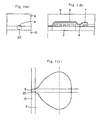
- FIGURES 5(a) and 5(b) of the accompanying drawings are a schematic front elevational view showing that surface of the transducer portion of a known thin-film head which is adapted to face a magnetic recording medium, and a perpendicular sectional and side elevational view of the head, respectively.
- the head comprises a magnetic member 10 composed of e.g. soft ferrite, a non-magnetic material 3 forming a gap layer, a thin-film conductor coil 4, an insulating film layer 5, a thick magnetic film 7 formed from e.g.
- a Permalloy, Sendust, or amorphous cobalt alloy serving to prevent the magnetic saturation of a main magnetic-pole film during recording, the main magnetic-pole film 8, and a protective film 9, which lie one upon another as shown in FIGURE 5(b).
- a plurality of layers have ends exposed in a surface facing the magnetic recording medium 30, and the magnetic member 10 for a return path to the recording medium 30 has a groove 2 which is filled with the non-magnetic material 3.
- the non-magnetic material 3 and the magnetic member 10, however, have therebetween a boundary plane 12 which is parallel to the main magnetic-pole film 8, as shown in FIGURE 5(a).
- a head including a magnetic member having orthogonal grooves, and at least a thin-film conductor coil, an inter-laminar insulating film, a main magnetic-pole film and a protective film formed one upon another immediately above the intersection of the grooves enables the magnetic flux to return not only to the area facing the main magnetic-pole film, but also along the track width, and exhibits an improved reproducing output.
- a thin-film perpendicular magnetic recording and reproducing head including a magnetic member for a return path having a principal surface formed with a first groove extending in parallel to a sliding surface adapted to face a magnetic recording medium, a non-magnetic material filling the groove, and at least a thin-film conductor coil, an interlaminar insulating film, a main magnetic-pole film and a protective film formed one upon another, the magnetic member being connected to the main magnetic-pole film though a via hole portion, the head having an exposed laminated surface defining the sliding surface, characterized in that the magnetic member has also a second groove formed in its principal surface, crossing the first groove orthogonally, and filled with a non-magnetic material, the conductor coil and the films being formed immediately above the intersection of the first and second narrow groove, the second groove being exposed in the sliding surface, and having a width which is smaller than that of the first groove, and is larger by 1 to 100 microns than that of the main magnetic-pole
- the thin-film head of this invention is characterized by including a magnetic member for a return path which is so shaped adjacent to a sliding surface adapted to face a magnetic recording medium, as to extend not only in the area facing a main magnetic-pole film, but also along the track width, though it has a portion interrupted by a non-magnetic material, as shown in FIGURES 1(a) to 1(c).
- the thin-film head of this invention can be manufactured easily and efficiently by using a grooved magnetic substrate 1 composed of a magnetic material, such as Ni-Zn or Mn-Zn ferrite, and having a principal surface formed with a plurality of spaced apart main grooves 2 each having a flat or stepped bottom, and a plurality of spaced apart narrow grooves 20 crossing the main grooves 2 at right angles thereto, the grooves 2 and 20 being filled with a non-magnetic material 3, such as glass, SiO2, Al2O3 or barium titanate, as shown in FIGURE 2.
- a non-magnetic material such as glass, SiO2, Al2O3 or barium titanate
- Each main or first groove 2 serves to prevent the leakage of magnetic flux between a main magnetic pole and a magnetic member for a return path.
- Each narrow or second groove 20 defines a gap layer having a width which is slightly (1 to 100 microns) larger than the track width.
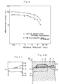
- the substrate 1 is used to make by a process including a series of steps a plurality of perpendicular thin-film heads each having a narrow groove 20 which is specifically sized and shaped relative to a main magnetic-pole film 8 in the sliding surface along which a magnetic recording medium is slidable, as shown in FIGURE 1(a).
- the magnetic head of this invention enables the magnetic flux produced by the main magnetic-pole film to return not only to the area facing it, but also along the track width, and exhibits improved recording and reproducing properties.
- Each of the main grooves 2 in the principal surface of the magnetic substrate 1 preferably has a width which is equal to the distance between the end of the thick magnetic film 7 and the end of the via hole portion 6 when the thin-film head assembly is made, and a depth of 3 to 100 microns
- each narrow groove 20 preferably has a width which is larger by 1 to 100 microns than that of the main magnetic-pole film 8, and a depth of 3 to 100 microns which is at least equal to that of the main groove 2.
- a plurality of main grooves each having a width of 0.15 mm, a depth of 0.025 mm and a length of 50 mm were formed by machining in a precisely finished surface of a substrate formed from Ni-Zn ferrite.
- a plurality of narrow grooves each having a width of 0.075 mm, a depth of 0.025 mm and a length of 50 mm were likewise formed so as to cross the main grooves at right angles thereto.
- the grooves were filled with Al2O3 in such a way that it might not form any more than one bubble larger than 5 microns per cubic millimeter.
- the surface of the substrate was mechanochemically polished.
- a copper film was formed by sputtering to form a thin-film conductor coil in a particular pattern on the polished surface of the substrate.
- An interlaminar insulating film was formed from a polyimide resin to cover the coil and its surface was smoothed by an etchback method.
- a thick magnetic film was formed by sputtering from an amorphous cobalt alloy in a particular pattern over the insulating film.
- a thin main magnetic-pole film was formed by sputtering from an amorphous cobalt alloy in a particular pattern on the thick magnetic film.
- a protective film was formed from Al2O3 on the top of the whole assembly.
- the assembly was cut to an appropriate size and shape to give a perpendicular thin-film head including a magnetic member for a return path having a specific groove configuration relative to the main magnetic-pole film in its sliding surface adapted to face a recording medium.
- a perpendicular thin-film head was likewise made from a substrate of Ni-Zn ferrite having a groove measuring 0.3 mm in width and 0.025 mm in depth, filled with glass, and defining a conventional gap layer.
- the two heads having different groove configurations were tested for their reproducing output characteristics.
- the characteristics were determined by self recording and reproducing under the conditions as set forth below.
- Powder - MgO powder having a particle size not exceeding 0.02 micron
- Machine used A 15 inch single-sided lapping machine
- Diamond - Powder having a particle size of 0.5 to 1 micron
Landscapes
- Engineering & Computer Science (AREA)
- Manufacturing & Machinery (AREA)
- Magnetic Heads (AREA)
Applications Claiming Priority (2)
| Application Number | Priority Date | Filing Date | Title |
|---|---|---|---|
| JP2050292A JPH03252906A (ja) | 1990-02-28 | 1990-02-28 | 垂直磁気記録再生薄膜ヘッド |
| JP50292/90 | 1990-02-28 |
Publications (2)
| Publication Number | Publication Date |
|---|---|
| EP0444903A2 true EP0444903A2 (de) | 1991-09-04 |
| EP0444903A3 EP0444903A3 (en) | 1992-01-08 |
Family
ID=12854837
Family Applications (1)
| Application Number | Title | Priority Date | Filing Date |
|---|---|---|---|
| EP19910301595 Withdrawn EP0444903A3 (en) | 1990-02-28 | 1991-02-27 | Thin-film perpendicular magnetic recording and reproducing head |
Country Status (3)
| Country | Link |
|---|---|
| US (1) | US5198950A (de) |
| EP (1) | EP0444903A3 (de) |
| JP (1) | JPH03252906A (de) |
Families Citing this family (3)
| Publication number | Priority date | Publication date | Assignee | Title |
|---|---|---|---|---|
| JP3943337B2 (ja) * | 2000-11-10 | 2007-07-11 | Tdk株式会社 | 薄膜磁気ヘッドの製造方法 |
| US6882258B2 (en) * | 2001-02-27 | 2005-04-19 | General Electric Company | Mechanical bell alarm assembly for a circuit breaker |
| US7116517B1 (en) * | 2002-12-18 | 2006-10-03 | Western Digital (Fremont), Inc. | Stitched pole write element with a T-shaped pole tip portion |
Family Cites Families (5)
| Publication number | Priority date | Publication date | Assignee | Title |
|---|---|---|---|---|
| JPS57123516A (en) * | 1981-01-23 | 1982-08-02 | Matsushita Electric Ind Co Ltd | Thin-film magnetic head |
| JPS59203213A (ja) * | 1983-05-04 | 1984-11-17 | Sumitomo Special Metals Co Ltd | 溝構造磁性基板の製造方法 |
| DE3527468A1 (de) * | 1984-08-01 | 1986-02-06 | Matsushita Electric Industrial Co., Ltd., Kadoma, Osaka | Magnetkopf fuer quermagnetische aufzeichnung und wiedergabe |
| US4777074A (en) * | 1985-08-12 | 1988-10-11 | Sumitomo Special Metals Co., Ltd. | Grooved magnetic substrates and method for producing the same |
| JPS63195816A (ja) * | 1987-02-09 | 1988-08-12 | Sumitomo Special Metals Co Ltd | 薄膜ヘツドの製造方法 |
-
1990
- 1990-02-28 JP JP2050292A patent/JPH03252906A/ja active Pending
-
1991
- 1991-02-14 US US07/655,167 patent/US5198950A/en not_active Expired - Fee Related
- 1991-02-27 EP EP19910301595 patent/EP0444903A3/en not_active Withdrawn
Also Published As
| Publication number | Publication date |
|---|---|
| EP0444903A3 (en) | 1992-01-08 |
| JPH03252906A (ja) | 1991-11-12 |
| US5198950A (en) | 1993-03-30 |
Similar Documents
| Publication | Publication Date | Title |
|---|---|---|
| US5225953A (en) | Magnetic thin film head of a single magnetic pole for perpendicular recording and reproduction | |
| US6190764B1 (en) | Inductive write head for magnetic data storage media | |
| CA1147855A (en) | Thin film magnetic head | |
| CA1151767A (en) | Magnetic head for perpendicular magnetic recording system | |
| EP0281931B1 (de) | Magnetkopf | |
| EP0357236A2 (de) | Verfahren für die Massenproduktion von Magnetköpfen | |
| US5181151A (en) | Thin-film perpendicular magnetic recording and reproducing head having thin magnetic shield film on side surfaces | |
| US5167062A (en) | Method of manufacturing magnetic write/read head and fabrication method | |
| US6101067A (en) | Thin film magnetic head with a particularly shaped magnetic pole piece and spaced relative to an MR element | |
| US6504677B1 (en) | Multi-layer stitched write head design for high data rate application | |
| US4843507A (en) | Magnetic head with laminated structure | |
| US4768121A (en) | Magnetic head formed by composite main pole film and winding core for perpendicular magnetic recording | |
| US4811142A (en) | Magnetic head for vertical magnetic recording and method of producing same | |
| US5198950A (en) | Thin-film perpendicular magnetic recording and reproducing head | |
| US5218499A (en) | Thin-film magnetic head for perpendicular magnetic recording having a magnetic member with grooves crossing at right angles formed in a principal surface thereof | |
| US5267392A (en) | Method of manufacturing a laminated high frequency magnetic transducer | |
| JPH06338033A (ja) | 複合型薄膜磁気ヘッド | |
| KR950009849B1 (ko) | 자기헤드 | |
| JP2720097B2 (ja) | 垂直磁気記録再生薄膜ヘッド | |
| JPH03252909A (ja) | 垂直磁気記録再生薄膜ヘッド用溝構造磁性基板 | |
| JPS6362804B2 (de) | ||
| JPS62114113A (ja) | 薄膜磁気ヘツド | |
| US5778514A (en) | Method for forming a transducing head | |
| JP2761969B2 (ja) | 垂直磁気記録再生薄膜ヘッド用積層基板 | |
| JPH04307408A (ja) | 垂直磁気記録再生薄膜ヘッド |
Legal Events
| Date | Code | Title | Description |
|---|---|---|---|
| PUAI | Public reference made under article 153(3) epc to a published international application that has entered the european phase |
Free format text: ORIGINAL CODE: 0009012 |
|
| AK | Designated contracting states |
Kind code of ref document: A2 Designated state(s): DE FR NL |
|
| PUAL | Search report despatched |
Free format text: ORIGINAL CODE: 0009013 |
|
| AK | Designated contracting states |
Kind code of ref document: A3 Designated state(s): DE FR NL |
|
| 17P | Request for examination filed |
Effective date: 19920706 |
|
| 17Q | First examination report despatched |
Effective date: 19940802 |
|
| STAA | Information on the status of an ep patent application or granted ep patent |
Free format text: STATUS: THE APPLICATION IS DEEMED TO BE WITHDRAWN |
|
| 18D | Application deemed to be withdrawn |
Effective date: 19941213 |