EP0444789B1 - Kodierung und Dekodierung von MAC-Videosignalen - Google Patents
Kodierung und Dekodierung von MAC-Videosignalen Download PDFInfo
- Publication number
- EP0444789B1 EP0444789B1 EP91301038A EP91301038A EP0444789B1 EP 0444789 B1 EP0444789 B1 EP 0444789B1 EP 91301038 A EP91301038 A EP 91301038A EP 91301038 A EP91301038 A EP 91301038A EP 0444789 B1 EP0444789 B1 EP 0444789B1
- Authority
- EP
- European Patent Office
- Prior art keywords
- video signal
- mac
- signal
- colour difference
- information
- Prior art date
- Legal status (The legal status is an assumption and is not a legal conclusion. Google has not performed a legal analysis and makes no representation as to the accuracy of the status listed.)
- Expired - Lifetime
Links
Images
Classifications
-
- H—ELECTRICITY
- H04—ELECTRIC COMMUNICATION TECHNIQUE
- H04N—PICTORIAL COMMUNICATION, e.g. TELEVISION
- H04N11/00—Colour television systems
- H04N11/06—Transmission systems characterised by the manner in which the individual colour picture signal components are combined
- H04N11/08—Transmission systems characterised by the manner in which the individual colour picture signal components are combined using sequential signals only
-
- H—ELECTRICITY
- H04—ELECTRIC COMMUNICATION TECHNIQUE
- H04N—PICTORIAL COMMUNICATION, e.g. TELEVISION
- H04N11/00—Colour television systems
- H04N11/04—Colour television systems using pulse code modulation
-
- H—ELECTRICITY
- H04—ELECTRIC COMMUNICATION TECHNIQUE
- H04N—PICTORIAL COMMUNICATION, e.g. TELEVISION
- H04N19/00—Methods or arrangements for coding, decoding, compressing or decompressing digital video signals
- H04N19/50—Methods or arrangements for coding, decoding, compressing or decompressing digital video signals using predictive coding
- H04N19/59—Methods or arrangements for coding, decoding, compressing or decompressing digital video signals using predictive coding involving spatial sub-sampling or interpolation, e.g. alteration of picture size or resolution
-
- H—ELECTRICITY
- H04—ELECTRIC COMMUNICATION TECHNIQUE
- H04N—PICTORIAL COMMUNICATION, e.g. TELEVISION
- H04N9/00—Details of colour television systems
- H04N9/79—Processing of colour television signals in connection with recording
- H04N9/7921—Processing of colour television signals in connection with recording for more than one processing mode
- H04N9/7925—Processing of colour television signals in connection with recording for more than one processing mode for more than one standard
Definitions
- This invention relates to the encoding and decoding of multiplexed analog components (MAC) video signals.
- MAC multiplexed analog components
- colour television (TV) signals have been transmitted using the PAL, NTSC and SECAM colour systems. Due to the huge amounts of monochrome equipment in existence when these three systems were initially contemplated, economic and bandwidth considerations imposed a large restraint on their designs. Specifically, the systems had to be compatible with existing monochrome systems in that they had to transmit their signals over existing channels and in that their signals had to be such that they could be received (in monochrome) on existing monochrome receivers as well as being received (in colour) on colour receivers. As a result, the systems were so designed that the chrominance (colour) information was transmitted within the same frequency band as the luminance information, the chrominance and luminance information or signals being combined to form a so-called composite signal.
- the MAC system was designed.
- There are several variants of the MAC system including normal definition MAC, widescreen MAC, high definition MAC, B-MAC, C-MAC, D-MAC, D2-MAC and so on. All of the variants are characterised by the fact that, instead of being sent in composite form, the chrominance and luminance signals are sent sequentially, that is on a time division multiplex basis, so that they cannot interfere with each other. Thus, cross-colour and cross-luminance cannot occur.
- Each line (that is, each line scanning interval) of the transmitted signal includes time-compressed chrominance information and time-compressed luminance information, the chrominance and luminance information being sent one after the other.
- the chrominance information comprises two colour difference signals. However, the two colour difference signals are not both sent during each line.
- the respective two colour difference signals are sent on a line sequential basis, that is during alternate lines.
- odd-numbered lines of a frame will contain one of the colour difference signals and even-numbered lines of the frame will contain the other of the colour difference signals.
- the sequence of the colour difference signals is reset between frames so that each one of the colour difference signals is always sent during lines of the same number of successive frames. That is, the (n)th line of each successive frame will always include one of the colour difference signals and the (n+1)th line of each successive frame will always include the other of the colour difference signals.
- the colour difference signals Prior to transmission, in an encoder for encoding signals into the MAC format, the colour difference signals are vertically sub-sampled to achieve the desired line sequential colour difference information. That is to say, alternate vertically adjacent samples of each of the colour difference signals are discarded to leave, for each line, samples for one only of the colour difference signals. Sub-sampling resulting in the elimination of every other sample will, of course, result in halving of the vertical Nyquist frequency. In the absence of any corrective measure, this would lead to vertical chrominance aliasing. So, the colour difference signals also have to be vertically prefiltered so that their spectra are restricted to a band substantially below the halved vertical Nyquist frequency.
- the filtering can be effected in an analog or digital finite impulse response (FIR) filter of conventional design, using appropriate weighting coefficients to achieve the desired bandwidth reduction.
- FIR finite impulse response
- the colour difference signals are subjected to a process known as "decimation” (passed through a “decimation filter”), in which the colour difference signals are vertically filtered and vertically sub-sampled.
- the recovered sub-sampled colour difference signals are interpolated to estimate the colour difference information that was discarded, prior to transmission, in the sub-sampling operation. That is to say, an interpolation filter estimates, for each line, that one of the two colour difference signals that was not transmitted for that line by taking averages between that one of the two colour difference signals transmitted during other lines, for example the two lines immediately above and below it.
- the transmitted luminance signal, the transmitted colour difference signals and the estimated colour difference signals can then be converted into a conventional format (such as RGB) for display.
- the signal degradation experienced in the event of multiple passes through the decimation filter and/or the interpolating filter represents a very serious problem which poses a severe obstacle to the successful development of MAC systems.
- a MAC signal encoder for encoding a video signal into MAC format, the encoder comprising:
- Encoders and decoders in accordance with the invention can be used in a variety of types of equipment. They can also be used on a stand alone basis: for example, an encoder in accordance with the invention could be used to encode a live or recorded signal immediately before it is sent to a transmitter for sending it to a satellite for broadcasting.
- a preferred use of the encoders and decoders is in recording signals on a video tape recorder (VTR) designed to record signals in MAC format and capable of reproducing such recorded signals, if desired, in a decoded (non-MAC) format.
- VTR video tape recorder
- Such a VTR can be provided with a codec (an encoder and a decoder) in accordance with the invention.
- the encoder of the codec is used to encode an input signal into MAC format so that it can be recorded in MAC format.
- the decoder of the codec can be used to decode a reproduced signal which is to be output in non-MAC format. With such an arrangement, the colour difference signals will be filtered only on the first occasion of the signal being passed through the codec, so that multiple generation copying does not give rise to the problem explained above.
- the marker information can in principle be of any recognisable form and can be inserted anywhere, for example in the video signal of MAC format or the video signal of non-MAC format, so as to be contained in the latter. It can, for example, be contained in luminance information of the signal, in which event it preferably is inserted in a vertical blanking interval so as not to interfere with the picture. For example, in the case of a 625 line system as used, for instance, in the UK, the marker information can be contained in line 21, where space not needed for other purposes is currently available.
- the marker information is such as to be visible if the vertical blanking interval is viewed, for instance by way of a monitor which can be switched into an underscanned mode (in which the vertical blanking interval is displayed above the picture).
- the marker information is in the form of a peak white level present during a predetermined interval of a line (for example for two microseconds after the start of the line) of the vertical blanking interval.
- the marker information is then not only visible, but can easily be identified whether the signal is in analog or digital form, for example by circuitry which is operative to look at the luminance level of the appropriate line at a predetermined timing (for example one microsecond) after the start of the line.
- a MAC signal is formed by encoding (multiplexing together) a luminance signal Y and two colour difference signals which, in similar manner to the components of a PAL signal, are based upon B - Y and R - Y.
- the colour difference signals as applied to an encoder for performing the encoding operation are referred to as Pb (the B - Y signal scaled to 0.7 V peak to peak) and Pr (the R - Y signal scaled to 0.7 V peak to peak).
- Each line (that is, each line scanning interval) of the transmitted MAC signal includes time-compressed chrominance information and time-compressed luminance information, the chrominance and luminance information being sent one after the other.
- one or the other of the colour difference signals Pb and Pr is time compressed to occupy about the first one third of each line and the luminance signal Y is time compressed to occupy about the remaining two thirds of each line.
- the two colour difference signals Pb and Pr are not both sent during each line. Rather, to reduce transmission bandwidth, the respective two colour difference signals Pb and Pr are sent on a line sequential basis, that is during alternate lines.
- odd-numbered lines of a frame will contain one of the colour difference signals (for example the signal Pb) and even-numbered lines of the frame will contain the other of the colour difference signals (for example the signal Pr).
- the sequence of the colour difference signals Pb and Pr is reset between frames so that each one of the colour difference signals is always sent during lines of the same number of successive frames. That is, the odd-numbered lines of successive frames will always include the same one of the colour difference signals (for example the signal Pb) and the even-numbered lines of successive frames will always include the other of the colour difference signals (for example the signal Pr).
- the colour difference signals Prior to transmission, in the encoder for encoding the luminance signal Y and the colour differences signals Pb and Pr into the MAC format, the colour difference signals are vertically sub-sampled to achieve the desired line sequential colour difference information. That is to say, alternate vertically adjacent samples of each of the colour difference signals are discarded to leave, for each line, samples for one only of the colour difference signals. Sub-sampling resulting in the elimination of every other sample will, of course, result in halving of the vertical Nyquist frequency. In the absence of any corrective measure, this would lead to vertical chrominance aliasing.
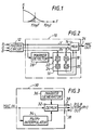
- Figure 1 is a graph of amplitude A versus frequency f showing the vertical frequency spectra of the colour difference signals Pb and Pr applied to the encoder.
- the spectra lie within a band below the vertical Nyquist frequency f(ny) of the original sampling.
- the sub-sampling results in the vertical Nyquist frequency being reduced by a factor (in this case two) equal to the extent of the sub-sampling. That is, the vertical Nyquist frequency of the sub-sampled colour difference signals Pb and Pr is reduced to a value f(ny)'.
- the colour difference signals Pb and Pr are vertically prefiltered prior to sub-sampling so that their spectra are restricted to a band substantially below the halved vertical Nyquist frequency f(ny)'.
- the colour difference signals Pb and Pr are passed through low-pass filters which prevent substantially the passage of those parts of their spectra above the halved vertical Nyquist frequency f(ny)'.
- the filters can be finite impulse response (FIR) filters of conventional design, implemented in either analog or digital form, using appropriate weighting coefficients to achieve the desired bandwidth reduction.
- FIR finite impulse response
- FIG. 2 shows a MAC encoder 10 embodying the invention for carrying out the operations described above. It is assumed that a video signal to be encoded is in RGB component form and that, prior to the signal being applied to the encoder 10, the signal is passed through a matrix circuit 12 which converts the RGB component signals into Y/Pb/Pr component signals for application to the encoder. (If desired, the matrix circuit could be included in the encoder 10.) In the encoder 10, the luminance signal Y is supplied to a multiplexer (MUX) 14 and the colour difference signals Pb and Pr are supplied to a decimator circuit or filter 16.
- MUX multiplexer
- the decimator circuit 16 comprises a low-pass vertical filter 18 and a vertical sub-sampler (S/S) 20 for the colour difference signal Pb and, likewise, a low-pass vertical filter 22 and a vertical sub-sampler (S/S) 24 for the colour difference signal Pr.
- the filters 18 and 22 and the sub-samplers 20 and 24 perform the operations explained above.
- the filtered and sub-sampled colour difference signals Pb and Pr output by the decimator circuit 16 are supplied to the multiplexer 14.
- the multiplexer 14 multiplexes together (including time compressing) the luminance signal Y and the filtered and sub-sampled colour difference signals Pb and Pr as described above to produce a MAC signal which is output on a line 26.
- the encoder 10 as so far described is of known construction.
- the encoder 10 is distinguished from the known construction by the following features.
- the encoder 10 includes a marker detector 28 which is connected to monitor or examine the incoming signal for the presence of marker information indicative of whether the signal has previously been MAC encoded. More specifically, since in the present embodiment the marker information comprises (as explained in more detail below) a marker or flag which is contained in the luminance signal Y at a predetermined position in every frame, the marker detector is connected to monitor the luminance signal Y (though it could instead monitor one or more of the RGB signals input to the matrix circuit 12). If the marker detector 28 does not detect the marker or flag, it takes no action. The encoder 10 then operates in the same manner as the known encoder.
- the marker detector 28 does detect the marker or flag, it is operative on the decimator circuit 16 to disable the operation of the filters 18 and 22, for example by causing the colour difference signals Pb and Pr to bypass the filters, so as to inhibit the above-described vertical filtering of the colour difference signals.
- the colour difference signals Pb and Pr are still vertically sub-sampled, they are not vertically filtered.
- FIG. 3 shows a MAC decoder 30 embodying the invention for decoding a signal in MAC format.
- the MAC signal is applied to a demultiplexer (DEMUX) 32 and to a Pb/Pr interpolator 34.
- the received colour difference signals Pb and Pr are interpolated to estimate the colour difference information that was discarded, prior to transmission, in the sub-sampling operation.
- the interpolator 34 comprises an interpolation filter that estimates, for each line, values for that one of the two colour difference signals that was not transmitted for that line by taking averages between that one of the two colour difference signals transmitted during other lines, for example the two lines immediately above and below it.
- the estimated values are passed to the demultiplexer 32, in which the transmitted luminance signal Y, the transmitted colour difference signals Pb and Pr and the estimated colour difference signals Pb and Pr are demultiplexed (which includes de-time compressing) or converted into a non-MAC format such as RGB or Y/Pb/Pr and output on lines 38.
- the decoder 30 as so far described is of known construction.
- the decoder 30 is distinguished from the known construction by the following feature.
- the decoder 30 includes a marker generator 36 operative to generate marker information of the nature set forth in the above description of the encoder 10 shown in Figure 2, and to cause the marker information to be contained in the non-MAC format signal output by the decoder 30.
- the marker information will indicate to the marker detector 28 of the encoder that the signal has previously been MAC encoded, and therefore that the colour difference signals Pb and Pr thereof have been vertically filtered as described above, as a result of which the colour difference signals will not be vertically filtered again.
- the marker generator 36 is shown as being connected to the demultiplexer 32 so as to insert the marker information during the course of demultiplexing. It should be appreciated, however, that the marker information can be inserted anywhere, provided that it appears in the non-MAC format signal output by the decoder 30.
- the marker information could be inserted into the MAC signal before the signal reaches the demultiplexer 32, for example by connecting the marker generator 36 to or in the line directing the MAC signal to the demultiplexer, or it could be inserted into the non-MAC signal output by the demultiplexer, for example by connecting the marker generator to or in one or more of the lines 38 (for example, if the marker information is to be contained in the luminance information, to or in the Y line only in the case of a Y/Pb/Pr output and to or in all three lines in the case of an RGB output).
- the marker information caused to be contained in the non-MAC format signal by the marker generator 36 of the decoder 30 and recognised by the marker detector 28 of the encoder 10 can in principle be of any recognisable form and can be contained anywhere in the non-MAC format signal. It can, for example, as suggested above in the description of the encoder 10 of Figure 2, be contained in luminance information of the signal, in which event it preferably is contained in a vertical blanking interval so as not to interfere with the picture. For example, in the case of a 625 line system as used, for instance, in the UK, the marker information can be contained in line 21, where space not needed for other purposes is currently available.
- the marker information is such as to be visible if the vertical blanking interval is viewed, for instance by way of a monitor which can be switched into an underscanned mode (in which the vertical blanking interval is displayed above the picture).
- the marker information is in the form of a simple peak white bar or level present for two microseconds after the start of a line (preferably, as mentioned above, line 21 in the case of a 625 line system) in every vertical blanking interval.
- the marker information is then not only visible, but it can easily be determined whether the signal is in either analog or digital form, for instance by causing the marker detector 28 to look at the luminance level of the appropriate line at a timing of one microsecond after active line start (that is, at the centre of the nominal position of the white bar) and to decide that the marker information is present if, at that time, the amplitude of the luminance signal Y is greater than 0.61V (if in analog form) or greater than an equivalent digital level (if in digital form). Also, the marker information is then readily capable of being recorded on a VTR.
- the present invention is applicable to any of the different versions of the MAC system, for example ordinary definition MAC, widescreen MAC, high definition MAC, B-MAC, C-MAC, D-MAC, D2-MAC and so on.
- the invention should also be applicable to any future type of MAC system or to any derivation of the MAC system characterised in that the chrominance information is divided into plural signals which are sent on a line sequential basis in such a manner that each line of the same number in successive frames carries the same such signal, and in that the plural signals are vertically filtered and vertically sub-sampled in the encoding process.
Landscapes
- Engineering & Computer Science (AREA)
- Multimedia (AREA)
- Signal Processing (AREA)
- Color Television Systems (AREA)
- Compression Or Coding Systems Of Tv Signals (AREA)
- Television Systems (AREA)
Claims (25)
- MAC-Signal-Codierer zur Codierung eines Videosignals in ein MAC-Format, wobei der Codierer (10) aufweist:eine Vertikal-Unterabtasteinrichtung (20, 24) zur Vertikal-Unterabtastung von Chrominanz-Informationen in dem Videosignal zur Erzeugung von vertikal-unterabgetasteten Farbdifferenzsignalen,eine Vertikal-Filtereinrichtung (18, 22) zur Vertikal-Filterung der Farbdifferenzsignale vor ihrer Vertikal-Unterabtastung, um somit ihre Spektren auf ein Band unterhalb der Vertikal-Nyquist-Frequenz der vertikal-unterabgetasteten Farbdifferenzsignale zu beschränken und,einen Multiplexer (26) zum Multiplexen der gefilterten und unterabgetasteten Farbdifferenzsignale und von Luminanz-Information des Videosignals zur Erzeugung eines Signals im MAC-Format,
gekennzeichnet durcheine Erfassungseinrichtung (28), die auf das Videosignal antwortet, das eine Markier-Information enthält, die anzeigt, daß das Signal früher MAC-codiert wurde, um die Vertikal-Filterung der Farbdifferenzsignale durch die Vertikal-Filtereinrichtung (18, 22) zu verhindern. - Codierer nach Anspruch 1,
bei dem die Erfassungseinrichtung (28) auf die Luminanz-Information des die Markier-Information enthaltenden Videosignals antwortet. - Codierer nach Anspruch 2,
bei dem die Erfassungseinrichtung (28) auf das die Markier-Information enthaltende Videosignal in einem Vertikal-Austastintervall von diesem antwortet. - Codierer nach Anspruch 3,
bei dem die Erfassungseinrichtung (28) auf ein solches Videosignal antwortet, das 625 Zeilen aufweist und die Markier-Information in der Zeile 21 davon enthält. - Codierer nach Anspruch 3 oder 4,
bei dem die Erfassungseinrichtung (28) auf das die Markier-Information enthaltende Videosignal als einen Spitzenwert-Weißpegel an einer vorbestimmten Taktung nach dem Start einer Zeile des Vertikal-Austastintervalls antwortet. - Verfahren zur Codierung eines Videosignals in ein MAC-Format, wobei das Verfahren die folgenden Schritte aufweist:Vertikal-Unterabtastung (20, 24) von Chrominanz-Informationen in dem Videosignal zur Erzeugung von vertikal-unterabgetasteten Farbdifferenzsignalen,Vertikalfilterung (18, 22) der Farbdifferenzsignale vor ihrer Vertikal-Unterabtastung, um somit ihre Spektren auf ein Band unterhalb der Vertikal-Nyquist-Frequenz der vertikal-unterabgetasteten Farbdifferenzsignale zu beschränken, und Multiplexen (26) der gefilterten und unterabgetasteten Farbdifferenzsignale und einer Luminanz-Information des Videosignals zur Erzeugung eines Signals in einem MAC-Format,
gekennzeichnet durchden Schritt der Prüfung (28) des Videosignals zur Bestimmung, ob es eine Markier-Information enthält, die anzeigt, daß das Signal früher MAC-codiert wurde, und für den Fall, daß das Videosignal die Markier-Information enthält, Verhinderung der Vertikal-Filterung der Farbdifferenzsignale. - Verfahren nach Anspruch 6,
bei dem der Prüfschritt (28) die Feststellung umfaßt, ob das Videosignal die Markier-Information in seine Luminanz-Information enthält. - Verfahren nach Anspruch 7,
bei dem der Prüfschritt (28) die Feststellung umfaßt, ob das Videosignal die Markier-Information in seinem Vertikal-Austastintervall enthält. - Verfahren nach Anspruch 8,
bei dem der Prüfschritt (28) die Feststellung umfaßt, ob ein solches Videosignal, das 625 Zeilen aufweist, die Markier-Information in seiner Zeile 21 enthält. - Verfahren nach Anspruch 8 oder 9,
bei dem der Prüfschritt (28) die Feststellung umfaßt, ob das Videosignal die Markier-Information als einen Spitzenwert-Weißpegel an einem vorbestimmten Zeitpunkt nach dem Start einer Zeile des Vertikal-Austastintervalls enthält. - MAC-Signal-Decodierer zur Decodierung eines Videosignals, das in einem MAC-Format vorliegt, in ein Videosignal im Nicht-MAC-Format, wobei der Decodierer (30) aufweist:eine Interpolationseinrichtung (34) zur Interpolation zwischen vertikal-unterabgetasteten Farbdifferenzsignalen in dem MAC-Format-Signal zur Erzeugung geschätzter Farbdifferenz-Information, undeinen Demultiplexer (32), der das MAC-Format-Signal und die geschätzte Farbdifferenz-Information aufnimmt und sie zur Erzeugung eines Videosignals in einem Nicht-MAC-Format demultiplext,
gekennzeichnet durcheine Markier-Einrichtung (36) zur Erzeugung von Markier-Information, die anzeigt, daß das Signal früher MAC-codiert wurde, und zur Veranlassung, daß die Markier-Information in dem Videosignal in dem Nicht-MAC-Format enthalten ist. - Decodierer nach Anspruch 11,
bei dem die Markier-Einrichtung (36) veranlaßt, daß die Markier-Information in der Luminanz-Information des Videosignals im Nicht-MAC-Format vorliegt. - Codierer nach Anspruch 12,
in dem die Markier-Einrichtung (36) veranlaßt, daß die Markier-Information in einem Vertikal-Austastintervall des Videosignals im Nicht-MAC-Format enthalten ist. - Decodierer nach Anspruch 13,
der ein Videosignal mit 625 Zeilen im Nicht-MAC-Format erzeugt, und bei dem die Markier-Einrichtung (36) veranlaßt, daß die Markier-Information in Zeile 21 des Videosignals mit 625 Zeilen in einem Nicht-MAC-Format enthalten ist. - Decodierer nach Anspruch 13 oder 14,
bei dem die Markier-Einrichtung (36) eine Markier-Information erzeugt, die sichtbar ist, wenn das Vertikal-Austastintervall angezeigt wird. - Decodierer nach Anspruch 15,
bei dem die Markier-Einrichtung (36) veranlaßt, daß die Markier-Information in dem Videosignal in einem Nicht-MAC-Format als ein Spitzenwert-Weißpegel während einem vorbestimmten Intervall einer Zeile des Vertikal-Austastintervalls enthalten ist. - Verfahren zur Decodierung eines Videosignals, das in einem MAC-Format vorliegt, in ein Videosignal in einem Nicht-MAC-Format, wobei das Verfahren die folgenden Schritte aufweist:Interpolation (34) zwischen vertikal-unterabgetasteten Farbdifferenzsignalen in dem MAC-Format-Signal zur Erzeugung geschätzter Farbdifferenz-Information, und Demultiplexierung (32) des MAC-Format-Signals und der geschätzten Farbdifferenz-Information zur Erzeugung eines Videosignals in einem Nicht-MAC-Format,
gekennzeichnet durchden Schritt der Erzeugung von Markier-Information (36) zur Anzeige, daß das Signal früher MAC-codiert wurde, und zur Veranlassung, daß die Markier-Information in dem Viedeosignal in einem Nicht-MAC-Format enthalten ist. - Verfahren nach Anspruch 17,
in dem die Markier-Information in Luminanz-Information des Videosignals in einem Nicht-MAC-Format enthalten ist. - Verfahren nach Anspruch 18,
bei dem die Markier-Information in einem Vertikal-Austastintervall des Videosignals in einem Nicht-MAC-Format enthalten ist. - Verfahren nach Anspruch 19,
das ein Videosignal in einem Nicht-MAC-Format mit 625 Zeilen erzeugt und in dem die Markier-Information in Zeile 21 des Videosignals im Nicht-MAC-Format mit 625 Zeilen enthalten ist. - Verfahren nach Anspruch 19 oder 20,
in dem die Markier-Information sichtbar ist, wenn das Vertikal-Austastintervall angezeigt wird. - Verfahren nach Anspruch 21,
in dem die Markier-Information ein Spitzenwert-Weißpegel ist, der während eines vorbestimmten Intervalls einer Zeile des Vertikal-Austastintervalls vorliegt. - Vorrichtung zur Aufzeichnung eines Videosignals, wobei die Vorrichtung einen MAC-Signal-Codierer gemäß einem der Ansprüche 1 bis 5 zur Codierung eines Videosignals vor seiner Aufzeichnung enthält.
- Vorrichtung zur Wiedergabe eines Videosignals, wobei die Vorrichtung einen MAC-Signal-Codierer gemäß einem der Ansprüche 11 bis 16 zur Decodierung eines Videosignals vor seiner Wiedergabe aufweist.
- Vorrichtung zur Aufzeichnung und Wiedergabe eines Videosignals, wobei die Vorrichtung einen MAC-Signal-Codierer gemäß einem der Ansprüche 1 bis 5 zur Codierung eines Videosignals vor seiner Aufzeichnung und einen MAC-Signal-Decodierer gemäß einem der Ansprüche 11 bis 16 zur Decodierung eines wiedergegebenen Videosignals aufweist.
Applications Claiming Priority (2)
| Application Number | Priority Date | Filing Date | Title |
|---|---|---|---|
| GB9004291 | 1990-02-26 | ||
| GB9004291A GB2241402B (en) | 1990-02-26 | 1990-02-26 | Encoding and decoding of MAC video signals |
Publications (3)
| Publication Number | Publication Date |
|---|---|
| EP0444789A2 EP0444789A2 (de) | 1991-09-04 |
| EP0444789A3 EP0444789A3 (en) | 1992-12-16 |
| EP0444789B1 true EP0444789B1 (de) | 1996-05-01 |
Family
ID=10671634
Family Applications (1)
| Application Number | Title | Priority Date | Filing Date |
|---|---|---|---|
| EP91301038A Expired - Lifetime EP0444789B1 (de) | 1990-02-26 | 1991-02-08 | Kodierung und Dekodierung von MAC-Videosignalen |
Country Status (6)
| Country | Link |
|---|---|
| US (1) | US5097320A (de) |
| EP (1) | EP0444789B1 (de) |
| JP (1) | JPH04211591A (de) |
| KR (1) | KR100194498B1 (de) |
| DE (1) | DE69119117T2 (de) |
| GB (1) | GB2241402B (de) |
Families Citing this family (5)
| Publication number | Priority date | Publication date | Assignee | Title |
|---|---|---|---|---|
| JP3095804B2 (ja) * | 1991-04-30 | 2000-10-10 | 株式会社リコー | 画像データ伝送装置および画像データ伝送方法 |
| KR0138749B1 (ko) * | 1992-01-23 | 1998-05-15 | 강진구 | 디인터리브방법 및 그 장치 |
| US5644361A (en) * | 1994-11-30 | 1997-07-01 | National Semiconductor Corporation | Subsampled frame storage technique for reduced memory size |
| US5627601A (en) * | 1994-11-30 | 1997-05-06 | National Semiconductor Corporation | Motion estimation with bit rate criterion |
| FI117754B (fi) | 2004-02-06 | 2007-02-15 | Kemira Pigments Oy | Titaanidioksidituote, sen valmistusmenetelmä ja käyttö fotokatalyyttinä |
Family Cites Families (6)
| Publication number | Priority date | Publication date | Assignee | Title |
|---|---|---|---|---|
| DE3704456C1 (de) * | 1987-02-13 | 1987-11-19 | Rohde & Schwarz | Anordnung zum Darstellen von MAC-Signalen auf einem Monitor |
| FR2613166B1 (fr) * | 1987-03-24 | 1989-06-23 | Labo Electronique Physique | Dispositif de transmission d'images a haute definition par un canal a bande passante relativement etroite |
| US4908697A (en) * | 1987-07-24 | 1990-03-13 | North American Philips Corporation | Two-line mac high definition television system |
| GB8729878D0 (en) * | 1987-12-22 | 1988-02-03 | Philips Electronic Associated | Processing sub-sampled signals |
| US4994899A (en) * | 1988-03-23 | 1991-02-19 | Scientific Atlanta, Inc. | Frequency generation for extended bandwidth MAC color television encoding and decoding |
| ES2081833T3 (es) * | 1988-09-16 | 1996-03-16 | Philips Electronics Nv | Sistema de television de alta definicion. |
-
1990
- 1990-02-26 GB GB9004291A patent/GB2241402B/en not_active Revoked
-
1991
- 1991-02-08 DE DE69119117T patent/DE69119117T2/de not_active Expired - Fee Related
- 1991-02-08 EP EP91301038A patent/EP0444789B1/de not_active Expired - Lifetime
- 1991-02-21 US US07/658,680 patent/US5097320A/en not_active Expired - Lifetime
- 1991-02-21 KR KR1019910002773A patent/KR100194498B1/ko not_active Expired - Fee Related
- 1991-02-26 JP JP3030940A patent/JPH04211591A/ja active Pending
Also Published As
| Publication number | Publication date |
|---|---|
| GB9004291D0 (en) | 1990-04-18 |
| KR920000201A (ko) | 1992-01-10 |
| DE69119117T2 (de) | 1996-10-24 |
| US5097320A (en) | 1992-03-17 |
| JPH04211591A (ja) | 1992-08-03 |
| KR100194498B1 (ko) | 1999-06-15 |
| EP0444789A3 (en) | 1992-12-16 |
| GB2241402A (en) | 1991-08-28 |
| DE69119117D1 (de) | 1996-06-05 |
| GB2241402B (en) | 1994-02-02 |
| EP0444789A2 (de) | 1991-09-04 |
Similar Documents
| Publication | Publication Date | Title |
|---|---|---|
| EP0589486B1 (de) | Kompatibilität von Fernsehübertragungen mit vergrössertem und normalem Bildformat | |
| Ninomiya et al. | An HDTV broadcasting system utilizing a bandwidth compression technique-MUSE | |
| US5353065A (en) | Apparatus for receiving wide/standard picture plane television signal | |
| EP0550213A1 (de) | Aufnahme und Wiedergabe von Farbvideosignalen | |
| EP0113932B1 (de) | Fernsehübertragungssystem | |
| KR960010492B1 (ko) | 서브나이키스트 샘플링된 영상 신호를 복조하기 위한 장치 및 그 복조방법 | |
| EP0444789B1 (de) | Kodierung und Dekodierung von MAC-Videosignalen | |
| WO1993000772A1 (fr) | Systeme de transmission de sous-echantillonnage pour amelioration de la qualite de transmission d'image en zone d'image a variation temporelle de signal d'image couleur en large bande | |
| CA2165761C (en) | Digital video signal recording/reproducing apparatus for storing a vertical resolution signal | |
| KR930000457B1 (ko) | 서브나이키스트 샘플링에 의한 영상신호의 대역압축 전송방식 | |
| US5227879A (en) | Apparatus for transmitting an extended definition TV signal having compatibility with a conventional TV system | |
| US4651195A (en) | Monochrome-compatible color slow scan television system | |
| CA1334686C (en) | Video signal recording/reproducing apparatus | |
| US5459523A (en) | Image transmission device | |
| EP0420205B1 (de) | Vorrichtung zum Verarbeiten eines Videosignals | |
| US4636835A (en) | Color television transmission or data storage system having time-division multiplex encoding and data generator and receiver suitable therefor | |
| US5126835A (en) | Method and apparatus for video signal dropout compensation | |
| HK72797A (en) | Process and device for decoding image signals containing additional information | |
| Holoch et al. | Improved PAL by a Combination of NTSC-SECAM-PAL | |
| JP3450845B2 (ja) | 広帯域カラー画像信号送信装置および受信装置 | |
| Holoch et al. | Improved PAL using a combination of NTSC, SECAM, and PAL | |
| Ninomiya | Hybrid High-Definition | |
| Storey et al. | Experience of the use of novel techniques for cost-effective wide-screen outside broadcasts | |
| JPH0832941A (ja) | 高品位テレビ受像機 | |
| Gardiner | PALplus widescreen broadcasting |
Legal Events
| Date | Code | Title | Description |
|---|---|---|---|
| PUAI | Public reference made under article 153(3) epc to a published international application that has entered the european phase |
Free format text: ORIGINAL CODE: 0009012 |
|
| AK | Designated contracting states |
Kind code of ref document: A2 Designated state(s): DE FR GB |
|
| PUAL | Search report despatched |
Free format text: ORIGINAL CODE: 0009013 |
|
| AK | Designated contracting states |
Kind code of ref document: A3 Designated state(s): DE FR GB |
|
| 17P | Request for examination filed |
Effective date: 19930510 |
|
| 17Q | First examination report despatched |
Effective date: 19950707 |
|
| GRAH | Despatch of communication of intention to grant a patent |
Free format text: ORIGINAL CODE: EPIDOS IGRA |
|
| GRAA | (expected) grant |
Free format text: ORIGINAL CODE: 0009210 |
|
| AK | Designated contracting states |
Kind code of ref document: B1 Designated state(s): DE FR GB |
|
| REF | Corresponds to: |
Ref document number: 69119117 Country of ref document: DE Date of ref document: 19960605 |
|
| ET | Fr: translation filed | ||
| PLBE | No opposition filed within time limit |
Free format text: ORIGINAL CODE: 0009261 |
|
| STAA | Information on the status of an ep patent application or granted ep patent |
Free format text: STATUS: NO OPPOSITION FILED WITHIN TIME LIMIT |
|
| 26N | No opposition filed | ||
| REG | Reference to a national code |
Ref country code: GB Ref legal event code: IF02 |
|
| PGFP | Annual fee paid to national office [announced via postgrant information from national office to epo] |
Ref country code: DE Payment date: 20090206 Year of fee payment: 19 |
|
| PGFP | Annual fee paid to national office [announced via postgrant information from national office to epo] |
Ref country code: GB Payment date: 20090204 Year of fee payment: 19 |
|
| PGFP | Annual fee paid to national office [announced via postgrant information from national office to epo] |
Ref country code: FR Payment date: 20090213 Year of fee payment: 19 |
|
| GBPC | Gb: european patent ceased through non-payment of renewal fee |
Effective date: 20100208 |
|
| REG | Reference to a national code |
Ref country code: FR Ref legal event code: ST Effective date: 20101029 |
|
| PG25 | Lapsed in a contracting state [announced via postgrant information from national office to epo] |
Ref country code: FR Free format text: LAPSE BECAUSE OF NON-PAYMENT OF DUE FEES Effective date: 20100301 |
|
| PG25 | Lapsed in a contracting state [announced via postgrant information from national office to epo] |
Ref country code: DE Free format text: LAPSE BECAUSE OF NON-PAYMENT OF DUE FEES Effective date: 20100901 |
|
| PG25 | Lapsed in a contracting state [announced via postgrant information from national office to epo] |
Ref country code: GB Free format text: LAPSE BECAUSE OF NON-PAYMENT OF DUE FEES Effective date: 20100208 |