EP0444088B1 - Pipeline-multiprozessorsystem - Google Patents
Pipeline-multiprozessorsystem Download PDFInfo
- Publication number
- EP0444088B1 EP0444088B1 EP89912813A EP89912813A EP0444088B1 EP 0444088 B1 EP0444088 B1 EP 0444088B1 EP 89912813 A EP89912813 A EP 89912813A EP 89912813 A EP89912813 A EP 89912813A EP 0444088 B1 EP0444088 B1 EP 0444088B1
- Authority
- EP
- European Patent Office
- Prior art keywords
- instruction
- token
- value
- operand
- tokens
- Prior art date
- Legal status (The legal status is an assumption and is not a legal conclusion. Google has not performed a legal analysis and makes no representation as to the accuracy of the status listed.)
- Expired - Lifetime
Links
Images


Classifications
-
- G—PHYSICS
- G06—COMPUTING OR CALCULATING; COUNTING
- G06F—ELECTRIC DIGITAL DATA PROCESSING
- G06F15/00—Digital computers in general; Data processing equipment in general
- G06F15/76—Architectures of general purpose stored program computers
- G06F15/82—Architectures of general purpose stored program computers data or demand driven
- G06F15/825—Dataflow computers
-
- G—PHYSICS
- G06—COMPUTING OR CALCULATING; COUNTING
- G06F—ELECTRIC DIGITAL DATA PROCESSING
- G06F9/00—Arrangements for program control, e.g. control units
- G06F9/06—Arrangements for program control, e.g. control units using stored programs, i.e. using an internal store of processing equipment to receive or retain programs
- G06F9/30—Arrangements for executing machine instructions, e.g. instruction decode
- G06F9/38—Concurrent instruction execution, e.g. pipeline or look ahead
- G06F9/3867—Concurrent instruction execution, e.g. pipeline or look ahead using instruction pipelines
-
- G—PHYSICS
- G06—COMPUTING OR CALCULATING; COUNTING
- G06F—ELECTRIC DIGITAL DATA PROCESSING
- G06F9/00—Arrangements for program control, e.g. control units
- G06F9/06—Arrangements for program control, e.g. control units using stored programs, i.e. using an internal store of processing equipment to receive or retain programs
- G06F9/44—Arrangements for executing specific programs
- G06F9/448—Execution paradigms, e.g. implementations of programming paradigms
- G06F9/4494—Execution paradigms, e.g. implementations of programming paradigms data driven
Definitions
- MIMD systems can be further classified by the level at which they extract parallelism, specifically, they can be classified by the size of the units of computation that they perform in parallel.
- Coarse grained systems are those in which relatively large units of computation are performed in parallel. Although the units of computation are performed in parallel, execution still proceeds sequentially within each unit.
- Fine grained systems in contrast, perform small units of computation in parallel. Since the units of computation that may be performed in parallel in fine-grained systems are much smaller than in coarse-grained systems, fewer operations are performed sequentially and the inherent potential for parallelism is much greater.
- MIMD systems the greatest inherent potential for parallel activity rests with MIMD systems.
- MIMD systems the greatest inherent potential for parallel activity is found with fine-grained systems.
- Such systems have small sized units of computation and provide for easy computation.
- processing elements that operate on fine grains of computation are readily composed to multiprocessor systems.
- the problem, however, in efficiently implementing such fine-grained systems is effectively controlling the extraordinary amount of parallel activity of the systems, particularly since the increase in parallelism results in a dramatic rise in inter-task communication.
- the increase in parallelism also presents complex computation scheduling synchronization problems.
- MIMD machines have produced only mildly encouraging results.
- such machines have used software as the primary tool for instilling parallelism.
- programmers have decided where to install parallelism and have had to account for the difficult interactions of the programs with the machine.
- the programmer has born the brunt of the burden for deciding how to bring about parallel execution.
- MIMD machines have proven unappealing to most users.
- the resulting software has tended to be difficult to debug, unreliable, and not portable. To make matters worse, these machines have not performed as well as expected, despite the level of effort required to operate them.
- Data flow machines are a special variety of fine-grained machines that attempt to execute models of data flow through a data processing system. These models are known as data flow diagrams. Data flow diagrams are comprised of nodes and edges. The nodes represent instructions, and the edges represent data dependencies. To be more precise, the nodes represent operators and the edges represent operands. Data flow machines operate by processing the operands.
- the data flow diagrams impose only a partial order of execution.
- the instructions are executed in data flow machines whenever the operands they require are available. Data flow machines are, thus, not constrained by the rigid total order of execution found in sequential machines. This flexibility allows data flow machines to schedule execution of instructions asynchronously. In contrast, sequential machines based on the von Neumann model execute instructions only when the instruction pointer is pointing to the instructions. The primary benefit of asynchronous scheduling is the greater exposure of latent parallelism.
- Dynamic data flow machines are those machines which can dynamically allocate an instance of a function. In other words, the memory required for an instance of a function need not be preplanned, rather it can be allocated when the function is executed.
- Static data flow machines in contrast, can only statically allocate an instance of a function. As such, they must preplan the storage required for each instance of the function prior to execution.
- the Tagged-Token Data Flow Architecture developed at the Massachusetts Institute of Technology is a leading example of a dynamic data flow machine. It is described in Arvind, S.A. Brobst, and G.K. Maa, "Evaluation of the MIT Tagged-Token Data Flow Project", Technical Report CSG Memo , MIT Laboratory for Computer Science, 1988.
- the tagged token data flow machine allows simultaneous applications of a function by tagging each operand with a context identifier that specifies the activation of the function to which it belongs.
- the combination of the tag and the operand constitutes a token.
- the tags of two tokens must match if they are destined to the same instruction.
- the tagged token architecture must have a means for correctly matching the tags.
- An associative memory has been relied upon as the matching mechanism.
- a data processing system and a method of executing an arithmetic/logical instruction according to the invention are set out in claims 1 and 11.
- a data processing system of a preferred embodiment is comprised of at least one processing element and a plurality of memory locations.
- the processing element includes a processing pipeline of four stages. The first stage fetches instruction from memory to operate on a token. The second stage of the pipeline performs operand matching on the token as indicated by the fetched instruction. The third stage continues processing on the token by performing an ALU operation specified by the fetched instruction. Lastly, the fourth stage of the pipeline forms a new token or tokens from the results of the ALU operation and the fetched instruction.
- This data processing system is preferably a multiple processor data flow processing system.
- the tokens referred to above are data objects that are comprised of two fields.
- the first field is a tag that includes a pointer to the beginning of an activation frame and a pointer to an instruction.
- Activation frames are contiguous blocks of memory locations that are used to store information necessary to execute a block of instructions. In particular, they serve as the meeting ground for matching operands destined to the same data flow node.
- the instruction pointer points to the instruction that is to be executed when the given token is processed in the pipeline of a processing element.
- the second field of the token is simply a data value. In terms of the data flow model, this data value typically represents an operand value.
- Each processing element includes not only a processing pipeline but also a token buffer.
- This buffer stores the tokens while they are waiting to be processed within the processing pipeline.
- Each processing element has its own token buffer.
- each of the processing elements preferably operates in parallel with its counterparts.
- the token buffer is preferably comprised of the plurality of stacks that are prioritized such that tokens leave a higher priority stack for the pipeline before they begin a lower priority stack. Since the buffer is organized as a stack, it operates on a last in first out (LIFO) basis. It should be noted, however, that the buffer need not operate in this manner, rather it may operate on a first in first out (FIFO) basis.
- LIFO last in first out
- each memory location within an activation frame includes a state field for indicating a current state of the memory location and a value field for holding a value.
- the state field may indicate a number of different types of information. For instance, it may indicate the data type of the value in a value field. Similarly, it may indicate whether a value is stored in the value field. It is this second type of indication that is utilized to implement the matching function.
- the matching function is an important part of execution of arithmetic/logical instructions within the data processing system.
- the course of execution of an arithmetic/logical instruction begins with fetching of the instruction. Once the instruction is fetched, a memory location indicated by the instruction is accessed. Typically, this memory location is within an activation frame. Once the memory location is accessed, the state field is examined and the value field is operated on as determined by the arithmetic/logical instruction and the current value in the state field. Once the state field and value field have been operated on, the arithmetic/logical instruction is either performed or not performed, depending upon the current state of the memory location and the instruction.
- the operations that are performed on the state field and value field is determined to a great extent upon the time at which the operand encoded by the token arrives at the memory location.
- a first operand of an instruction is stored in the memory location when the memory location is empty.
- the state field is changed to reflect that an operand of the instruction is stored in the memory location.
- a second operand of the instruction is received.
- the memory location is checked to see if the first operand is stored therein. Since the first operand is already stored in the memory location, it is read out of the memory location and sent with the second available operand to be further processed.
- the state of the memory location be changed to indicate that the memory location is empty.
- the above approach is applicable with dyadic operations; however, when monadic operations are specified by the instruction, the operand value of the current token is forwarded to the processing element without the necessity of examining the contents of the memory location.
- each token contains an instruction pointer within its tag field. When a token enters the first stage of the pipeline (i.e., the instruction fetch stage), this pointer is utilized to locate the particular instruction.
- Each instruction contains a matching rule for matching operands. It also contains a rule for computing an effective address of a storage location on which the matching rule operates. Additionally, the instruction contains an ALU operation to be performed by the ALU of the data processing system and lastly, a token forming rule for forming new tokens that result from execution of the instruction.
- the dyadic and monadic matching rules have been discussed above but the sticking matching rule has of yet, not been discussed.
- the sticking matching rule tells the system to write a value of a token into the value field of a location if the state field of the location indicates that another value is not present. When it writes such a value it changes the state field location to indicate that a value is now present. On the other hand, if the value of the token is a constant, this value is written into the value field, but the state field is changed to indicate that not a normal value is present but rather that a constant value is present. If a normal value is present within the value field and a constant value subsequently arrives, the constant value is exchanged for the normal value. Furthermore, once the constant value is written into the value field, it is not removed until explicitly cleared. All accesses to the memory location after that point merely read a constant value out of the memory location.
- the rule for computing an effective address of a storage location as specified by the instruction selects one of three possible addressing approaches.
- the memory location is specified at an absolute address indicated by an offset that is contained within the instruction.
- the memory location is an address located at the address specified by the activation frame pointer of the tag offset by the offset contained within the instruction.
- the third option employs yet another approach. In this final approach the memory location is at the address pointed to by the pointer to an instruciton offset by the offset contained within the instruction.
- the ALU operation indicated by the instruction tells the system what operation is sought to be performed by the ALU on the operands. For instance, if the ALU operation was specified as an addition operation when the ALU operation stage of the pipeline acted on the given token, it would add the two operands passed to it.
- the final rule specified by the instruction is the token forming rule. This rule tells the system how to form new output tokens from the operations that have been performed. This rule is employed in the tag forming portion of the ALU operation stage as well as in the token forming stage.
- the processing pipeline preferably contains a capability to handle exceptions.
- One means that may be employed is to have each activity associated with a token recorded as the token enters the pipeline. When an exception occurs, the value in the register remains unchanged until the exception is resolved. The resolution of the exception is performed by issuing an exception handling token. This exception handling token preferably may not be interrupted.
- each processing element is preferably assigned a given region of storage in which activation frames encode is stored with that processing element.
- a token may indicate the processing element for which it is destined by encoding within the tag a processing element designation.
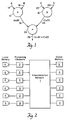
- FIG. 1 illustrates a data flow diagram for (AxB)+(CxD).
- the operands i.e., A, B, C, and D
- the operators i.e., x and +
- Node 10 represents a multiplication operation. That node 10 has two input edges 14 and 16 that represent A and B respectively.
- the output edge 18 from node 10 has the value AxB.
- node 12 which also represents a multiplication operation, has input edges 20 and 22 that represent C and D respectively.
- Output edge 24 has the value CxD.
- the two output edges 18 and 24 from these nodes 10 and 12 then enter an addition node 26.
- the resulting output edge 28 represents (AxB)+(CxD).
- each of the operations represented by the nodes would be performed in sequential order.
- the machine would first multiply A times B, then it would multiply C times D and lastly, it would add the product A times B and C times D. There is, however, no reason to impose such an order if the operands are available.
- the operations AxB and CxD are performed simultaneously. The resulting products are subsequently summed.
- the data flow machine substitutes the arbitrary sequential order imposed on such operations with an order imposed by the operations themselves.
- FIG. 2 A view of the major components of the preferred embodiment of the present invention is shown in Figure 2.
- the present invention includes a plurality of processing elements 3, each associated with an assigned region of memory 4, and global memory units 2.
- An interconnection network 1 comprised of logic circuitry is provided to facilitate communication amongst processing elements 3 as well as amongst global memory units 2 and processing elements 3.
- Each of the processing elements 3 may access any of the global memory units 2 and acts in parallel with the other processing elements 3.
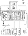
- FIG. 3 shows a typical processing element 3 in more detail.
- each processing element 3 includes a processing pipeline 36. Also included is a token queue 34 for storing tokens waiting to be processed. An assigned local portion 4 of global memory is allocated for storing activation frames 45 and code 32 for processing use. To provide exception handling capabilities, an exception handler 43 and a set of registers 41 are provided within the processing element 3.
- the memory 4 is distinguishable from the memory of traditional machines built under the von Neumann model. Instead of merely consisting of a value, each of the memory locations of the present invention comprises of two fields: a presence field and a value field.
- This memory organization in the present invention is significant, for it alters the common view of memory being merely a location for storing values.
- the dynamically assigned portion of memory 4 in the present invention has both a presence state and a value.
- the presence state may affect the value's significance, as well as alter the execution of instructions on the value. Further, the presence field may be manipulated independently from the value field. This design of memory makes it a more powerful tool, as will be more apparent from the discussion that follows.
- the memory 4 is used to store activation frames 45, heap storage 6 and code sections 32. Alternatively, an implementation may have separate memories for code 32 and activation frames 45.
- Activation frames 45 can be viewed as all the locations required for the invocation of a function or a code block. They play a particularly important role in the present invention, for they constitute the working memory in which tokens with matching tags meet. Tokens will be discussed in more detail below.
- tokens 20 are akin to embellished operands that identify not only the operand values but also identify the particular activation of an instruction to which they belong.
- a token 30 can be viewed as a tuple comprising a tag (c.s p ) and a value (v).
- the tag identifies the instruction and activity associated with the operand that the token represents.
- the tag is comprised of three fields: a context pointer (c), a statement number (s), and a port indicator (p).
- the context pointer (c) points to the beginning of an activation frame 45 in which the operand represented by the token will be matched.
- the statement number (s) points to a specific memory location where the instruction of the operand is stored, and the port (p) indicates whether the token enters a node representing the instruction on the left input edge or the right input edge.
- the processing element 2 of Figure 3 is perhaps most easily viewed as a token processing system. It processes tokens 30 to bring about execution of instructions 32. In terms of the data flow model, this system processes operands to execute data flow diagrams, and it continues processing operands until told to stop. In more accurate terms, the tokens trigger the production of activities that are performed in the pipeline 36.
- tokens 30 leave the token queue 34 whereupon they enter the processing pipeline 36.
- Multiple tokens are typically present in different stages of the pipeline at any given time. Each such token is processed in parallel with the other tokens in the pipeline.
- the pipeline represents a second level of parallelism within the present invention that is distinct from the parallelism attributable to the simultaneous computations of multiple processors.
- More than one token 30 may enter the pipeline at a time, but generally only one token enters the pipeline at a time.
- the number of tokens 30 that may simultaneously enter the pipeline 36 is dictated by the multiprocessing capability of the particular design employed; that is, each processing element may operate on multiple tokens in parallel.
- the first stage of the processing pipeline 36 is the instruction fetch stage 38. In this stage, the system looks at the statement number (s) contained in the tag of the incoming token 30. This statement number (s) corresponds to the memory location for the instruction that is to operate on the token 30. After determining the statement number, the system retrieves the instruction at that location (see the memory location pointed to by arrow 31 in Figure 4).
- An instruction of the present invention can be viewed as a tuple.
- an instruction equals (E.r, W, A, T.d) where E.r specifies a method of determining the effective address for the storage location on which the matching rule will operate; W specifies the matching rule; A specifies the ALU operation; and T.d specifies the token forming rule.
- E.r specifies a method of determining the effective address for the storage location on which the matching rule will operate
- W specifies the matching rule
- A specifies the ALU operation
- T.d specifies the token forming rule.
- the token 30 and information from the instruction 32 are passed on to the operand matching stage 40 of the pipeline 36.
- the system looks to match operands destined for the same node (i.e. those having like tags differing only as to port).
- This stage is the means for the system to check if all the operands necessary for execution of an instruction 32 are available or not. If they are available, the instruction 32 is executed. If they are not available the operand specified by the token is generally written into the matching location. The specifics of what occurs are discussed in more detail below.
- the ALU operation stage 42 which is comprised of a tag former 42A and an ALU 42B.
- the tag former 42A forms the tag portion of output tokens
- the ALU forms the value portion of output tokens.
- the operation specified by the instruction is performed by an ALU 42B within the stage.
- new tags for the results of the ALU operation are formed by the tag former 42A.
- the tag former 42A and ALU 42B may be further pipelined into substages so as to balance overall performance.
- the tags are formed in accordance with the token forming rule of the instruction being executed.
- the output from this stage 42 enters the token forming stage 44 where the output tokens are formed.
- the resulting output tokens that typically carry the result of the operation then may travel to a number of different locations. First, they may travel within the processing element 2 to the token queue 34 or to the pipeline 36. Second, they may travel to other processing elements 3, and third, they may travel to a memory unit 2. Where they travel is dictated by the tag portion of each output token, for the tag specifies a particular processing element 2 or memory unit 3 as will be discussed below.
- the output token's tag specifies which memory unit 2 is to be accessed.
- the output token 30 also specifies the operation to be performed on the memory location (i.e. a read operation or a write operation).
- the memory controller of the memory unit 2 uses the operation specification to perform the desired operation. If a read is requested, the memory unit 2 produces a token 30 comprising the data read of out the memory unit 2 and a tag specifying a given processing element. Once produced, this token 30 travels to the appropriate processing element where it joins the other tokens 30 being processed by the destination processing element.
- Outputs tokens 30 may also travel, as mentioned above, to other processing elements 3.
- they are directed to the interconnection network 1 where they travel to the processing element 3 specified by the tag of the token 30. Once there, they join other tokens at the processing element 3 and are processed. All of the tokens in a single processing element 3 have tags that specify the same processing element 3.
- Each processing element 3 can communicate with all other processing elements and with any memory unit 2. To communicate with such components, it need only generate an output token having a tag that specifies the processing element 3 or memory unit 2 to which it is destined. Moreover, such communications can be performed in parallel with ongoing computations, for the processing elements 3 need not wait for a response to the communication.
- an activation frame must first be allocated before it can be used.
- an activation frame is allocated for each routine that is performed.
- the activation frame is allocated. This allocation is performed by the operating system.
- the operating system maintains a list of free activation frames such that when a request for a new activation frame is received, it simply pops an activation frame off the free list and assigns it to the call of the routine. Moreover, when the call to the routine is completed, the activation frame is added back on to the free list. In performing such allocations and deallocations, the operating system makes certain that the same activation frame is not assigned to multiple routine calls at the same time.
- each activation frame is processed by a specific processing element, and each processing element may be allocated thousands of activation frames. Since the activation frames are allocated as required and requested with execution of prior code blocks, the processing elements are called upon dynamically with execution of the code.
- Routines are code blocks and calls to such routines are made by prior code blocks. These code blocks are defined by the compiler which decides which nodes of a data flow graph constitute a code block and thus share a single activation frame. The compiler, thus, establishes the interprocessor granularity of the process. Smaller code blocks characterize a fine grain system having greater potential for parallelism with increased interprocessor communications.
- code is not shared; rather each processing element 3 has a copy of the entire code in its assigned memory 4. All of the instructions encoded within the code are not performed by each processing element. Instead, only those instructions that are pointed to by the tokens processed by the given processing element 3 are executed by that processing element 3. Thus, only a proportional share of the entire code is typically performed by a given processing element.
- a cache system may be used to load code as required.
- the system can look to perform matching of operands.
- the operand matching stage 40 looks to the E.r field contained with the instruction 32 that is to be executed.
- the E.r field specifies one of three effective addressing modes.
- One possible effective addressing mode is frame relative mode.
- frame relative mode the address of the memory location is located within an activation frame 45 by adding an offset (r) to the context pointer (c) contained within the tag of the token 30. This scheme is illustrated in Figure 4. Note the arrow 35 in Figure 4 from c pointing to the beginning of the activation frame 45 and note the other arrow 33 pointing to the location specified by the context (c) plus the offset (r).
- absolute mode specifies the address as the absolute address (r).
- code relative mode the address is specified by the statement number from the tag plus the offset (r).
- Matching rules are basically a means of generating activities.
- an activity can be thought of as a tuple (c.s, v l , v r , A, T.d) where c.s is the context pointer and statement number from the tag shared by the matching tokens; v l is the value of the token on the left port; v r is the value of the token on the right port; A is an ALU operation; and T.d is the token forming rule.
- What matching rule is applied depends on the operation specified in the instruction and depends on the operands.
- the matching rule that is most commonly used operates on two operands. This rule is referred to as W dyadic .
- W dyadic This rule is referred to as W dyadic .
- the system looks at the memory location within an activation frame specified by the effective address and checks the presence field. If a value is currently residing in the value field, the presence field equals "present”, and if a value is not currently residing there, the presence field equals "empty".
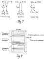
- the system 50 If the location's presence field indicates that it is in the "empty” state 48 ( Figure 5), the system 50 writes the value of the token into the value field of that memory location and changes the presence field to the "present” state 52. On the other hand, if the presence field is initially in the "present” state 52, the value field of the memory location is read, and an activity is issued 54.
- This scheme greatly simplifies the task of matching operands in dyadic operations. There is no longer the need for costly associative memory. Further, if one operand arrives prior to another it is not lost. Rather, it merely waits until the other is available.
- This aspect of the scheme reflects the asynchronous nature of the scheduling of execution of the instructions. In addition, a location in an activation frame need only be large enough to store a value and a state. The incoming tag of the first token to arrive may be discarded as it can be reconstructed from the tag of the second token to arrive.
- W monadic a different matching rule is applied.
- W monadic the left input port is used for input in monadic operations.
- the value field of the token on the left input port is read and an activity is issued. The presence state is not affected. The activity takes on the context (c), statement number (s), and value (v l ) of the input token on the left input port.
- (c.s l , v l ) ⁇ (c.s l , v l , v l , A, T.d)
- Constant operands to which this rule is applied are of two types. The first type is literal constants which are those known at the time of compilation. The second type is frame constants which are those values that may be established in an activation frame to be shared by many activities within a given invocation of a code block.
- Figure 6 shows the state transition diagram of W sticky . It allows a single active operand to be written into the location specified by the effective address prior to the arrival of the constant.
- the presence state is the "empty" state 56 and an active operand is in the matching stage, the operand's value is written 62 into the location, and the presence state is changed to the "present” state 58.
- the active operand must be at the left port input. If the constant arrives after the active operand (i.e., an input operand subsequently arrives on the right port), the value of the constant is exchanged with the value of the operand in the location, and an activity is issued 66. The presence state is changed to the "constant" state 60.
- the presence state need not be limited to encoding the presence or absence of a value, rather the presence state may also encode other information such as data types.
- the presence state may dynamically alter the execution of an instruction. For instance, if an instruction specifies the sticky matching rule, the operation performed at the memory location on which the matching rule acts is determined by the presence state. Thus, the instruction is conditioned on the presence state and performs different operations given different presence states.
- the activities are passed on to the next stage of the pipeline 36: the ALU operation stage 42.
- the central aim of this stage is to produce tags and values to pass on to the token forming stage 44.
- This stage relies on the A and T.d fields on the instruction 32 to direct system activity.
- the token forming rule, T.d specifies how the new tags and values are to be formed.
- the tags formed are in large part determined by the d field of the token forming rule.
- the d field specifies the destination addresses to be given the newly formed tokens. In particular, d equals (s1.p', s2.p").
- the first is the arithmetic rule denoted as T arith . It directs the ALU operation stage to apply the ALU operation (A) to the two values (v l, v r ) in the activity to generate an output value (v'). At least one token is produced and a second token (noted in brackets in Figure 7) may be produced.
- the output tags for the tokens (c.s' p' and c.s" p" ) are generated by applying increments (s1 and s2) to the statement number (s) contained in the incoming tags and by supplying new ports (p' and p") as specified by the d field of the token forming rule. Note that under this rule these output tokens have the same context as the original tokens.
- the second token forming rule, the send rule is denoted as T send . It sets the output token tag equal to the left value (v l ) of the activity which is data type TAG, and it sets the output token value equal to the right value (v r ) of the activity. It can generate another token if necessary, but it generates the new token's tag in the same manner as they are generated in the arithmetic rule by adding an increment to the stated number.
- the value field of the second output token is set equal to the right port value (v r ).
- the primary aim of this rule is to send a value to a different context. As such, it provides an inter-activation communication capability.
- the third and final basic rule is the extract rule, T extract which sends a value equal to the current context to an instruction within the current context. It can only generate one output token. It generates the two new tags (c.s' p' , c.s" p" ) from the activity tag (c.s) by adding increments (s1 and s2) to s as is done in the arithmetic rule. The first generated tag (c.s' p' ) is used as the output token's tag, and the second tag (c.s" p" ) is used as the output token's value.
- the extract rule and the send rule may combined to form an extract-send rule that sends a tag from within one context (c), as an argument to another context ( ⁇ ).
- the output token equals ( c ⁇ .( s ⁇ + s2) p" , c.s' p' ).
- T inc-s-send Another example of a combination token forming rule is the inc-s-send rule denoted as T inc-s-send . It allows an adjustment to the new s field by employing the second increment (s2) and the second port indicator (p") of the d field.
- T inc-s-send can be represented by: This instruction is used primarily for passing arguments and results.
- An additional combination token forming rule is the T fetch rule. It combines all three of the basic token forming rules. This rule is used to read elements from an array where ⁇ is the base address and v r is an index. Specifically,
- T switch acts in a manner consistent with the switch instruction discussed below.
- (c.s, v l , TRUE, A, T switch .d) ⁇ (c.s' p' , v l ) and (c.s, v l , FALSE, A, T switch .d) ⁇ (c.s" p" , v l ).
- the token formation stage 44 can be implemented with the assistance of a number of multiplexers (76 and 78 in Figure 8).
- the values and tags produced by the ALU operation stage 42 are fed into multiplexers which select the appropriate combinations as dictated by the token forming rule (T.d).
- the select lines of the multiplexer are controlled by the opcode (T.d) of the instruction. The opcodes will be discussed in greater detail below.
- Tokens 30 generated by the token forming stage 44 typically exit the pipeline 36 and return to the token queue 34. They are subsequently processed by the pipeline 36. Thus, there is a continuous flow through the pipeline until execution is completed. They may, however, travel to other destinations.
- the token forming stage 44 contains logic that examines the output token to see where it is destined and routes the output token accordingly.
- the other destinations that output tokens may travel include other processing elements 3 and memory units 2.
- An output token may travel to another processing element when a change-tag instruction (which will be described below) is executed that sends the output token to a new context associated with a different processing element 3. Further, an output token may travel to a memory unit 2 when a memory access instruction is specified by the tag. Such memory access instructions (e.g., read, write) are handled asynchronously by the memory units 2.
- the processing element need not wait while the memory access is being performed, rather it continues the processing.
- the actual memory access is performed by a controller within the particular memory unit 2 that is accessed. If appropriate, a token is sent by the memory unit 2 back to a given processing element 3 when the memory access is completed.
- Such asynchronous memory accesses constitute a third level of parallelism of the present invention, for the memory accesses are performed in parallel with the computations of the pipelines 36 of the various processing elements 3.
- a traditional queue may be used, but one optimization is for the queue to be comprised of a series of stacks (See Figure 3).
- stacks See Figure 3
- the idea behind the use of stacks is to try to create a sort of cache queue.
- a FIFO buffer would be useful, but not as practical for the present purposes.
- a FIFO would not easily provide for priority scheduling since, in a FIFO scheme, all tokens must wait their turn to be processed.
- a FIFO controls parallelism in the wrong way. If the tasks to be executed are viewed as a tree wherein those tasks that must be executed early in the execution process to allow other tasks to be executed are near the top of the tree, a FIFO approach would unfold the tree in a breadth-first manner.
- a LIFO approach can control unfolding in such a depth-first manner.
- the LIFO approach induces more locality than the FIFO approach. More importantly, a LIFO queue can be cached from local memory, whereas a FIFO queue is difficult to cache.
- the preferred embodiment uses stacks that are organized by priority.
- the tokens 30 are removed off the highest priority stack 70 ( Figure 3) until it is empty. Once the highest priority stack 70 is empty, the tokens 30 are removed from the next highest priority stack 72. This continues until execution is complete.
- a preferred implementation is to utilize only two stacks. Most tokens enter the highest priority stack 70, but some tokens are set aside in the next highest stack 72 to delay their processing.
- One option that may be used to determine priority for purposes of deciding which stack a token 30 enters is to encode the priority in the token 30 as part of the tag. This option has the advantage of being dynamic but results in an increase in the complexity of the system. Such an approach can encode priority dynamically but can also permit static control.
- the other option is to have the priority encoded in the destination as specified by the d field of the token forming rule of an instruction. This option is more static than encoding priority in the tag but has the benefit of being readily implemented.
- This stacking scheme allows for high priority tokens 30 to be processed quickly and early on in the execution of the instructions. This characteristic allows instructions which are condition precedents to the execution of a number of waiting instructions to be fully executed early in the execution process so as to free the path for execution of the waiting instructions. The net result is greater control over exposed parallelism.
- Another optimization embodied within the present invention is to provide a direct path (74 in Figure 3) for output from the pipeline 36 back into the pipeline 36 input.
- This path 74 bypasses the token queue 34.
- only a single port queue is required since only one output or one input as needed for a given cycle. If two output tokens are produced by the pipeline 36, one of the tokens 30 follows the bypass path 74 to be recirculated into the pipeline 36, and the other enters the token queue 34. If only one output token is produced by the pipeline 36, it follows the bypass path 74. If no token is then produced, a token is removed from the token queue and inserted into the pipeline 36.
- the present invention also concerns an optimization for exception handling.
- the system included in the present invention includes a special register set (41 in Figure 3).
- This register set 41 records activities in the pipeline 36. In particular, it records the tag, the left value (v l ), and the right value (v r ) of each activity in the pipeline 36. These registers figure into system operation when an exception occurs.
- An exception is an event such as mismatched data types in an operation, an attempt to divide by zero, etc.
- the instruction set plays a particularly important role in system operation.
- the instruction set is comprised of several different classes of instructions.
- One of the major classes of instructions is the dyadic arithmetic instruction class. This class of instruction perform arithmetic operations on two input operands.
- a typical example of a dyadic arithmetic instruction is the add instruction. This instruction can be summarized as: add Inputs : Outputs : (c.s l , v l ) (c.s' p' , v l + r ) (c.s r , v r ) [(c.s" p" , v l + v r )]
- a second class of instructions completes the set of arithmetic instructions.
- This second class is known as the monadic arithmetic instructions. They, like their dyadic counterparts, perform arithmetic operations. They, however, only act on one operand as opposed to two operands.
- Identity instructions represent an additional class of instruction.
- a primary instruction of this class is the identity instruction.
- the identity instruction passes the value of the input operand to another context.
- the gate instruction differs in that it copies the operand of the left input port and forwards that value when a value, called a trigger, is received on the right input port.
- Conditional instructions are used to institute conditional execution.
- the sole conditional instruction employed is the switch instruction. It demands two input operands. One of the input operands must be a value, and the other input must be a boolean. It produces one of two possible output value choices for the given inputs. Which output value is chosen depends on the value of the boolean input.
- Tag manipulation is carried out by a special class of tag manipulation instructions.
- This class contains three basic instructions.
- the first such instruction, change-tag can be summarized as: It is useful in communicating values between contexts. As noted, it requires two inputs. The value of the left input denotes the new context, and the value of the right input equals the value to be forwarded to the new context. Together these two input values comprise an output token.
- the resulting output token has a tag that shares the context with the input operand. It has a statement number that is sum of an increment with the statement number of the input. Moreover, the value field of the output token equals a tag in the same context as the input but has a statement number that is the sum of an additional increment with the statement number.
- the adjust-offset instruction can be summarized as: It provides a more complex operation. It utilizes two inputs. The first input's value specifies a new tag, and the second input's value specifies an offset. This instruction produces up to two output tokens. The first output token is in the same context as the inputs and has a value equal to the first input's value offset by the second input's value. The second output token also has the same value and shares the same context with the inputs, but its statement number is offset.
- the present system can readily provide for iterative operations, such as loops. It provides for loop implementation by assigning each iteration of a loop a new context. It then uses a change-tag instruction on the new context to send to the current iteration the tokens from the previous iteration. When the iteration is complete, it frees the context so that the context can be assigned to the next iteration. As such, the parent context can be passed from iteration to iteration. Hence, the loop unfolds during execution as a tail recursion of the N activation frames, where N is the number of iterations in the loop. To maintain efficiency in this approach, activation frames used in loops are recycled.
- an activation frame is allocated every time a procedure is called.
- the operating system of the data flow processing system maintains a list of free activation frames. When a procedure is called it pops an activation frame off the free list. Similarly, when a procedure call is completed, it no longer needs the activation frame so the activation frame it used is returned to the free list.
- the preferred embodiment of the present invention is a multiprocessor system. It, thus, must be able to communicate readily amongst processing elements 3.
- the preferred embodiment provides this capability by allowing tokens to freely flow from one processing element to another.
- the present invention is easily composed from individual processing elements. Since the same entities account for intra-processor traffic as well as inter-processor traffic, composition of multiple processing elements into a multiple processor system is easily achieved. Further, the fine-grained nature of the computations that are performed in parallel, likewise, allows such easy composition of single processing elements 2 into the multiple processor system. The fine-grained nature of the system also provides the benefit of facilitating easy compilation of code.
- a simple and workable approach is to assign each processing element a region of storage (See Figure 9).
- the tokens specify the processing element 2 that is assigned a given context through their tags.
- the two leading bits of the context pointers indicate the appropriate processing element.
- This approach has the advantage of removing the possibility of interprocessor conflict and the advantage of providing rapid access to memory.
- the assignments of storage space is not necessarily fixed; hence, space used an an activation frame by one processing element 2 may subsequently be used by another processing element 2.
- the approach has the additional advantage of making it possible to dynamically reallocate the partitions.
- One disadvantage of partitioning the address space concerns the allocation of large data structures.
- the present system interleaves such large data structures across multiple processors to produce an even distribution of network traffic and processor loads. This interleaving is performed word-by-word.
- Non-interleaved and interleaved approaches are provided for by conceptually dividing the address space into regions where increments to the context advance either within a processor or across processors depending on the subdomain specified.
- each memory location has associated presence bits. It is helpful if a large number of these presence bits can be changed simultaneously with a single instruction. To facilitate this capability, presence bits for adjacent locations are coalesced into words of the size equal to a machine word. In the preferred embodiment, there are two presence bits for each memory location. Thirty-two bits constitute a word. Thus, 16 sets of presence bits are stored as a word.
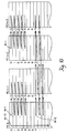
- the preferred embodiment utilizes a 72 bit word wherein 64 bits are a value field and 8 bits are a type field. Tokens are comprised of two words (See Figure 11). The first word is the tag and the second word is a value-part. Tags are of data type, TAG, whereas value-parts may be of several data types including TAG, FLT (floating point), INT (integer) and BITS (unsigned integer).
- Tags can be further broken down into a number of fields (See Figure 12).
- the leading bit of a tag indicates the port of the operand. A zero indicates the left port, and a one indicates the right port.
- the next 7 bits are the MAP field (See Figure 13).
- the first 2 bits of the MAP field are the HASH indicator which selects an interleaving strategy. The strategies are listed in the table of Figure 13.
- the other 5 bits are N field which equals the logarithm base two of the number of processors in the subdomain.
- IP instruction pointer
- the PE follows the instruction pointer, IP, field, that points to an instruction in memory and is 10 bits long.
- the final field of a tag is the FP field. It is a frame pointer and is 22 bits long. It points to the particular frame amongst those assigned a particular subdomain.
- the tag c.s is formed primarily out of the PE, FP and IP fields.
- c is comprised of the frame pointer FP, and the processing element designation PE such that PE comprises the most significant bits of c and FP comprises the least significant bits of c.
- s is comprised of PE and IP. PE comprises the most significant bits of s, and IP comprises the least significant bits of s.
- Instructions are only 32 bits long and comprised of only four fields: OPCODE, r, PORT and s (See Figure 14).
- OPCODE is 10 bits long and specifies an instruction OPCODE. Also 10 bits long is r. It is an unsigned offset used to compute the effective address of the operand.
- PORT defines the port for the destination tags.
- s is an offset to IP for one of the destination tags in twos complement form. If two destination tags are required by a given instruction, the second tag is generated by adding 1 to the incoming IP and setting port to 1.
- the operand matching stage 40 can be subdivided into three substages.
- the first substage 80 computes the effective address of the memory location where the operand matching takes place.
- the second substage 82 operates on the presence bits, and the third substage 84 either fetches or stores the operand at the effective address.
- the 10 bit OPCODE 90 field is used as an address to a first level decode table.
- Entries 109 in the first level decode table have four fields.
- a BASE field 92 specifies the base address for an entry in the second level decode.
- the TMAP field 94 specifies one of 32 type maps.
- the PMAP field 96 specifies one of 64 presence maps and lastly, the EA field 98 specifies the effective address generation mode.
- the OPCODE 90 is used to look up a first level decode table entry 109, and the EA field 98 of the entry is examined. It is 2 bits long. If both bits are zero, the address equals FP + r; if both bits are one, the address equals r; and if the leading bit is one and the trailing bit is a zero, the address equals IP+r.
- the TMAP (94 in Figure 15) field is also examined.
- the TMAP field 94 selects one of 32 type maps.
- the type maps are two dimensional arrays of size 256 by 2. Each entry has 2 bits. These 2 bits represent a mapping from the port and the data type of the value of the token in the first substage.
- the token, effective address and type code are passed on to the next substage 82 ( Figure 3).
- the second substage 82 is the presence bits substage.
- the system looks at the memory location specified by the particular address. From the location it reads the 2 presence bits. It uses these bits along with the port of the token in the substage, the type code bits 100 that were read from the type map and the PMAP field 96 of first level code entry to look up an entry 110 in the presence map table.
- the presence map table has sixty-four entries and each entry has four fields.
- the BRA field 102 is for four-way branch control and will be discussed below.
- the FZ field 104 determines whether the force-to-zero override is exerted. It, likewise, will be discussed more below.
- the FOP field 106 specifies which operand fetch/store operation is to be performed (i.e., read, write, exchange, or exchange-decrement).
- the final field 108 specifies the new value of the presence bits. It is denoted as NEXT.
- the fetch/store operation specified by the FOP field is carried out.
- the contents of the location specified by the effective address are passed on to the next stage of the pipeline.
- the BRA field 102 of the presence map and the BASE field 92 of the first level decode entry are ORed to produce an address in a second level decode.
- the second level decode table entry is used to specify parameters used in system operation. If the FZ field 104 is one, the BASE field 92 is forced to zero before being ORed.
- the net result is the second level decode table entry 111 is set as an absolute address of 0, 1, 2 or 3.
- the above-described system relieves the programmer of the herculean task of instilling parallelism into the data processing system. Since parallelism is inherent in the instruction set and implemented via hardware, this system is much easier to use than present parallel processing machines.
- the matching mechanism has been simplified so as to remove the inbred complexity found in associative memory systems.
- the unique memory design is primarily responsible for the diminished overhead.
- the fine-grained nature of the present system provides a number of benefits. First, it exposes the maximum amount of parallelism. Second, it can readily tolerate memory latency because it can process other tokens while a memory access request is being serviced. Third, it is easier to compile than coarse-grained systems. In sum, the present invention optimizes performance, simplicity and cost effectiveness.
Landscapes
- Engineering & Computer Science (AREA)
- Theoretical Computer Science (AREA)
- Software Systems (AREA)
- Physics & Mathematics (AREA)
- General Engineering & Computer Science (AREA)
- General Physics & Mathematics (AREA)
- Computer Hardware Design (AREA)
- Advance Control (AREA)
- Multi Processors (AREA)
- Memory System (AREA)
Claims (15)
- Datenverarbeitungssystem mit markierten Token (Belegungs-, Zugangs-Steuerblöcken), welches aufweist:einen Puffer (34) zum Empfangen von Datentoken (30), wobei jeder Token einen Kontextindikator, einen Zeiger auf einen Befehl (s) und einen Operandenwert (v) aufweist;Speicherbefehle für Speicher (4); undein auf einen Token ansprechender Prozessor (36), zum Bestimmen, ob ein passender Operand bzw. Vergleichsoperand zuvor gespeichert worden ist und wo ein passender Operand zuvor gespeichert worden ist, um das Ausführen eines arithmetischen/logischen Befehls auf den passenden Operanden und den vom Token getragenen Operandenwert zu veranlassen,gekennzeichnet dadurch,daß der Speicher (4) eine Mehrzahl von Aktivierungsrahmen (45) speichert, wobei jeder Aktivierungsrahmen Mehrfach-Speicherstellen zum Verwenden beim Ausführen eines Befehlsblocks aufweist und der Kontextindikator jedes Tokens einen Zeiger (c) auf einen Aktivierungsrahmen aufweist, wobei der Prozessor Operanden in von den Token identifizierten Aktivierungsrahmen speichert und bestimmt, ob ein passender Operand zuvor in einem vom Token identifizierten Aktivierungsrahmen gespeichert worden ist, um das Ausführen eines arithmetischen/logischen Befehls zu veranlassen.
- Datenverarbeitungssystem nach Anspruch 1, wobei eine Speicherstelle, in welcher ein Operand gespeichert ist, die Stelle ist, bei welcher Vergleichen bzw. passendes Verbinden von Operanden einer bestimmten Befehlsausführung stattfindet, und jede Speicherstelle ein Statusfeld und ein Wertefeld umfaßt, wobei das Statusfeld anzeigt, ob das Wertefeld einen Wert enthält.
- Datenverarbeitungssystem nach Anspruch 1 oder 2, wobei jeder Prozessor eine Verarbeitungs-Pipeline aufweist, welche in Verbindung mit den Speicherstellen und dem Puffer zum Verarbeiten von in dem Puffer gespeicherten Token steht, wobei die Pipeline umfaßt:eine Befehlsabrufstufe zum Abrufen von Befehlen, um die Token in der Pipeline zu behandeln;eine Operanden-Vergleichs- bzw. Zusammenpassungs-Stufe zum Vergleichen bzw. zum passenden Verbinden der auf den abgerufenen Befehl ansprechenden Operanden;eine Operationsstufe zum Durchführen von durch den abgerufenen Befehl spezifizierten Operationen; undeine Token-Bildungsstufe zum Bilden neuer Token, welche Ergebnisse der durch den abgerufenen Befehl spezifizierten Operationen tragen.
- Datenverarbeitungssystem nach Anspruch 1, 2 oder 3, das sowohl einen Puffer zum Speichern von Token, welche zu verarbeitende Operanden repräsentieren, wobei jeder Token eine Marke zum Anzeigen einer Adresse eines auf den Token einwirkenden Befehls aufweist, als auch einen Aktivierungsrahmen und ferner einen Wert zum Speichern eines Stücks von Daten bzw. eines Datums aufweist.
- Datenverarbeitungssystem nach einem der vorstehenden Ansprüche, welches einen Puffer zum Speichern von Token aufweist, welche Operanden- und abzuarbeitende Befehle bezeichnen, wobei ein abgerufener Befehl eine Vergleichs- bzw. Zusammenpassungs-Vorschrift zum Vergleichen bzw. passenden Verbinden von Operanden, eine Vorschrift zum Berechnen einer effektiven Adresse einer Speicherstelle, auf welche die Zusammenpassungs-Vorschrift wirkt, eine Recheneinheit (ALU)-Operation, die von einer Recheneinheit des Datenverarbeitungssystems ausgeführt wird, und eine Token-Bildungs-Vorschrift zum Bilden neuer Token, welche aus der Befehlsausführung resultieren, codiert.
- Datenverarbeitungssystem nach einen der vorstehenden Ansprüche, wobei das Datenverarbeitungssystem ein paralleles Mehrfachprozessorsystem ist.
- Datenverarbeitungssystem nach einem der vorstehenden Ansprüche, wobei das Datenverarbeitungssystem ein Datenflußverarbeitungssystem ist.
- Datenverarbeitungssystem nach einem der vorstehenden Ansprüche, wobei das System Operanden auf eine gemeinsam verwendete Speicherstelle leitet, um Operanden zu vergleichen bzw. passend zu verbinden.
- Datenverarbeitungssystem nach Anspruch 3, welches eine Mehrzahl von Registern aufweist zum Aufzeichnen von Vorgängen, welche mit den Token in jeder Stufe der Pipeline verbunden sind, so daß, falls eine Ausnahme auftritt, ein die Ausnahme verursachender Vorgang vorhanden ist, und einen Ausnahme-Handler zum Beheben von in der Pipeline auftretenden Ausnahmen, der die Mehrzahl der Register untersucht, um einen Vorgang für jede auftretende Ausnahme zu finden.
- Datenverarbeitungssystem nach einem der vorstehenden Ansprüche, wobei das System Vergleichs- bzw. Zusammenpassungs-Vorschriften befolgt, welche eine befestigende Vergleichs- bzw. Zusammenpassungs-Vorschrift einschließt, die dem System mitteilt, einen Wert eines Tokens in ein Wertefeld einer Speicherstelle zu schreiben, falls ein Statusfeld der Stelle anzeigt, daß ein anderer Wert nicht vorhanden ist, und das Statusfeld der Stelle ändert, um anzuzeigen, daß der Wert vorhanden ist, falls der Wert des Tokens keine Konstante ist, und das Status feld der Stelle ändert, um anzuzeigen, daß eine Konstante vorhanden ist, falls der Wert des Tokens eine Konstante ist.
- Verfahren zum Ausführen eines arithmetischen/logischen Befehls in einem Datenverarbeitungssystem, welches die folgenden Schritte aufweist:a) Abrufen des arithmetischen/logischen Befehls, der durch den Befehlszeiger bezeichnet wird, in Erwiderung auf ein Datentoken (30), welches einen Kontextindikator, einen Zeiger auf einen Befehl (s) und einen Operandenwert (v) aufweist;b) Bestimmen, ob ein passender Operand bzw. Vergleichsoperand zuvor gespeichert worden ist; undc) Ausführen des Befehls auf den passenden Operand und den vom Token getragenen Operandenwert, wo ein passender Operand zuvor gespeichert worden ist;dadurch gekennzeichnet, daß der Schritt b) des Bestimmens aufweist:b1) Zugänglichmachen eines Rahmens von durch den Kontextindikator angezeigten Speicherstellen, um einen Operanden zu speichern und einen Operanden zum Verwenden beim Ausführen des arithmetischenlogischen Befehls festzulegen; undb2) Bestimmen, ob der arithmetische/logische Befehl durch Prüfen eines gegenwärtigen Zustandes des Rahmens der Speicherstellen auszuführen ist, um zu bestimmen, ob ein bei der Ausführung des Befehls zu verwendender Operand zuvor in dem Rahmen der Speicherstellen gespeichert worden ist.
- Verfahren nach Anspruch 11 in einem Datenflußverarbeitungssystem mit folgenden Schritten:Bereitstellen von Token, welche als die arithmetischen/logischen Befehle abrufbar sind, wobei jeder Token einen Rahmenzeiger, einen Befehlszeiger und einen Wert aufweist, wobei der Befehlszeiger für einen Befehl ist, welcher die Werte der Token mit identischen Rahmenzeigern und identischen Befehlszeigern verarbeitet;Adressieren einer Speicherstelle im Speicher, welche durch den Rahmenzeiger und den Befehlszeiger bezeichnet wird, in Antwort auf einen Token;Bestimmen, ob ein Wert in der adressierten Speicherstelle gespeichert ist; und
falls ein Wert gespeichert ist, Ausführen des durch den Befehlszeiger bestimmten Befehls auf den gespeicherten Wert und den Wert des Tokens, um einen neuen Token zu erzeugen, und
falls der Wert nicht gespeichert ist, Speichern des Wertes des Tokens in der Speicherstelle. - Verfahren nach Anspruch 11 oder 12, welches die Schritte aufweist:a) Speichern eines ersten verfügbaren Operanden des Befehls in einer leeren Speicherstelle;b) Ändern eines Zustandes der Speicherstelle, um wiederzuspiegeln, daß ein Operand des Befehls bei der Speicherstelle gespeichert ist;c) Festlegen eines zweiten verfügbaren Operanden des Befehls;d) Prüfen der Speicherstelle, um zu erkennen, ob der erste verfügbare Operand des Befehls darin gespeichert ist; unde) Lesen des ersten verfügbaren Operanden von der Speicherstelle und Senden des Operanden an ein Verarbeitungsmittel zum Ausführen des Befehls.
- Verfahren nach Anspruch 11, 12 oder 13, wobei das Datenverarbeitungssystem ein Mehrfachprozessorsystem ist.
- Verfahren nach Anspruch 11 in einem Datenflußverarbeitungssystem, welches folgenden Schritt aufweist:
Bereitstellen von für die arithmetischen/logischen Befehle abzurufenden Token, wobei jeder Token einen Rahmenzeiger, einen Befehlszeiger und einen Wert aufweist, wobei der Befehlszeiger auf einen Befehl zeigt, welcher bestimmt, ob alle zur Verarbeitung erforderlichen Operanden in einem Aktivierungsrahmen von Mehrfachspeicherstellen verfügbar sind, auf welche der Rahmenzeiger zeigt, und das Verarbeiten von Werten von Token, welche an einen gemeinsamen Aktivierungsrahmen gerichtet sind, verursacht.
Applications Claiming Priority (5)
| Application Number | Priority Date | Filing Date | Title |
|---|---|---|---|
| US27449888A | 1988-11-18 | 1988-11-18 | |
| US274498 | 1988-11-18 | ||
| US396480 | 1989-08-21 | ||
| US07/396,480 US5241635A (en) | 1988-11-18 | 1989-08-21 | Tagged token data processing system with operand matching in activation frames |
| PCT/US1989/005105 WO1990005950A1 (en) | 1988-11-18 | 1989-11-16 | Data flow multiprocessor system |
Publications (2)
| Publication Number | Publication Date |
|---|---|
| EP0444088A1 EP0444088A1 (de) | 1991-09-04 |
| EP0444088B1 true EP0444088B1 (de) | 1996-02-07 |
Family
ID=26956858
Family Applications (1)
| Application Number | Title | Priority Date | Filing Date |
|---|---|---|---|
| EP89912813A Expired - Lifetime EP0444088B1 (de) | 1988-11-18 | 1989-11-16 | Pipeline-multiprozessorsystem |
Country Status (5)
| Country | Link |
|---|---|
| US (1) | US5241635A (de) |
| EP (1) | EP0444088B1 (de) |
| JP (1) | JPH04503416A (de) |
| DE (1) | DE68925646T2 (de) |
| WO (1) | WO1990005950A1 (de) |
Families Citing this family (95)
| Publication number | Priority date | Publication date | Assignee | Title |
|---|---|---|---|---|
| EP0576749B1 (de) | 1992-06-30 | 1999-06-02 | Discovision Associates | Datenpipelinesystem |
| US5353418A (en) * | 1989-05-26 | 1994-10-04 | Massachusetts Institute Of Technology | System storing thread descriptor identifying one of plural threads of computation in storage only when all data for operating on thread is ready and independently of resultant imperative processing of thread |
| WO1990014629A2 (en) * | 1989-05-26 | 1990-11-29 | Massachusetts Institute Of Technology | Parallel multithreaded data processing system |
| DE4104568A1 (de) * | 1990-02-15 | 1991-08-29 | Hitachi Ltd | Verfahren und vorrichtung zur programmverarbeitung |
| JP2682232B2 (ja) * | 1990-11-21 | 1997-11-26 | 松下電器産業株式会社 | 浮動小数点演算処理装置 |
| US5430850A (en) * | 1991-07-22 | 1995-07-04 | Massachusetts Institute Of Technology | Data processing system with synchronization coprocessor for multiple threads |
| US5414821A (en) * | 1991-12-17 | 1995-05-09 | Unisys Corporation | Method of and apparatus for rapidly loading addressing environment by checking and loading multiple registers using a specialized instruction |
| IL100598A0 (en) * | 1992-01-06 | 1992-09-06 | Univ Bar Ilan | Dataflow computer |
| US5371684A (en) * | 1992-03-31 | 1994-12-06 | Seiko Epson Corporation | Semiconductor floor plan for a register renaming circuit |
| US5842033A (en) | 1992-06-30 | 1998-11-24 | Discovision Associates | Padding apparatus for passing an arbitrary number of bits through a buffer in a pipeline system |
| US5809270A (en) | 1992-06-30 | 1998-09-15 | Discovision Associates | Inverse quantizer |
| US5768561A (en) | 1992-06-30 | 1998-06-16 | Discovision Associates | Tokens-based adaptive video processing arrangement |
| US6112017A (en) | 1992-06-30 | 2000-08-29 | Discovision Associates | Pipeline processing machine having a plurality of reconfigurable processing stages interconnected by a two-wire interface bus |
| US6435737B1 (en) | 1992-06-30 | 2002-08-20 | Discovision Associates | Data pipeline system and data encoding method |
| US6330665B1 (en) | 1992-06-30 | 2001-12-11 | Discovision Associates | Video parser |
| US6067417A (en) | 1992-06-30 | 2000-05-23 | Discovision Associates | Picture start token |
| US6047112A (en) | 1992-06-30 | 2000-04-04 | Discovision Associates | Technique for initiating processing of a data stream of encoded video information |
| US6079009A (en) | 1992-06-30 | 2000-06-20 | Discovision Associates | Coding standard token in a system compromising a plurality of pipeline stages |
| EP0586767A1 (de) * | 1992-09-11 | 1994-03-16 | International Business Machines Corporation | Selektive Datenerfassung für Software-Ausnahmezustände |
| JPH06124352A (ja) * | 1992-10-14 | 1994-05-06 | Sharp Corp | データ駆動型情報処理装置 |
| DE69327504T2 (de) * | 1992-10-19 | 2000-08-10 | Koninklijke Philips Electronics N.V., Eindhoven | Datenprozessor mit Operationseinheiten, die gemeinsam Gruppen von Registerspeichern benutzen |
| US5761407A (en) * | 1993-03-15 | 1998-06-02 | International Business Machines Corporation | Message based exception handler |
| US5861894A (en) | 1993-06-24 | 1999-01-19 | Discovision Associates | Buffer manager |
| JP2560988B2 (ja) * | 1993-07-16 | 1996-12-04 | 日本電気株式会社 | 情報処理装置および処理方法 |
| US5765014A (en) * | 1993-10-12 | 1998-06-09 | Seki; Hajime | Electronic computer system and processor element for processing in a data driven manner using reverse polish notation |
| US5448730A (en) * | 1993-12-14 | 1995-09-05 | International Business Machines Corporation | Correlating a response with a previously sent request in a multitasking computer system using pipeline commands |
| US5984512A (en) | 1994-07-29 | 1999-11-16 | Discovision Associates | Method for storing video information |
| US5598546A (en) * | 1994-08-31 | 1997-01-28 | Exponential Technology, Inc. | Dual-architecture super-scalar pipeline |
| CN101211255B (zh) | 1994-12-02 | 2012-07-04 | 英特尔公司 | 对复合操作数进行压缩操作的处理器、设备和计算系统 |
| US5710923A (en) * | 1995-04-25 | 1998-01-20 | Unisys Corporation | Methods and apparatus for exchanging active messages in a parallel processing computer system |
| WO1997008623A1 (en) * | 1995-08-23 | 1997-03-06 | Symantec Corporation | Coherent file system access during defragmentation operations on a storage media |
| US5761740A (en) * | 1995-11-30 | 1998-06-02 | Unisys Corporation | Method of and apparatus for rapidly loading addressing registers |
| US6792523B1 (en) * | 1995-12-19 | 2004-09-14 | Intel Corporation | Processor with instructions that operate on different data types stored in the same single logical register file |
| US5857096A (en) * | 1995-12-19 | 1999-01-05 | Intel Corporation | Microarchitecture for implementing an instruction to clear the tags of a stack reference register file |
| US5940859A (en) | 1995-12-19 | 1999-08-17 | Intel Corporation | Emptying packed data state during execution of packed data instructions |
| US5701508A (en) | 1995-12-19 | 1997-12-23 | Intel Corporation | Executing different instructions that cause different data type operations to be performed on single logical register file |
| US6065108A (en) * | 1996-01-24 | 2000-05-16 | Sun Microsystems Inc | Non-quick instruction accelerator including instruction identifier and data set storage and method of implementing same |
| US5956518A (en) * | 1996-04-11 | 1999-09-21 | Massachusetts Institute Of Technology | Intermediate-grain reconfigurable processing device |
| US6128299A (en) * | 1996-08-23 | 2000-10-03 | Virata Ltd. | System for low-cost connection of devices to an ATM network |
| US5778233A (en) * | 1996-10-11 | 1998-07-07 | International Business Machines Corporation | Method and apparatus for enabling global compiler optimizations in the presence of exception handlers within a computer program |
| US5983266A (en) * | 1997-03-26 | 1999-11-09 | Unisys Corporation | Control method for message communication in network supporting software emulated modules and hardware implemented modules |
| US5944788A (en) * | 1997-03-26 | 1999-08-31 | Unisys Corporation | Message transfer system and control method for multiple sending and receiving modules in a network supporting hardware and software emulated modules |
| US5999969A (en) * | 1997-03-26 | 1999-12-07 | Unisys Corporation | Interrupt handling system for message transfers in network having mixed hardware and software emulated modules |
| US5842003A (en) * | 1997-03-26 | 1998-11-24 | Unisys Corporation | Auxiliary message arbitrator for digital message transfer system in network of hardware modules |
| US6064818A (en) * | 1997-04-10 | 2000-05-16 | International Business Machines Corporation | Straight path optimization for compilers |
| RU2148857C1 (ru) * | 1998-02-20 | 2000-05-10 | Бурцев Всеволод Сергеевич | Вычислительная система |
| US6148392A (en) * | 1998-09-08 | 2000-11-14 | Hyundai Electronics Industries Co., Ltd. | Low power implementation of an asynchronous stock having a constant response time |
| US20030172248A1 (en) * | 2000-06-13 | 2003-09-11 | Streltsov Nikolai Victorovich | Synergetic computing system |
| GB0019341D0 (en) * | 2000-08-08 | 2000-09-27 | Easics Nv | System-on-chip solutions |
| US6880070B2 (en) * | 2000-12-08 | 2005-04-12 | Finisar Corporation | Synchronous network traffic processor |
| US7383421B2 (en) * | 2002-12-05 | 2008-06-03 | Brightscale, Inc. | Cellular engine for a data processing system |
| WO2003038645A2 (en) * | 2001-10-31 | 2003-05-08 | University Of Texas | A scalable processing architecture |
| JP4272371B2 (ja) * | 2001-11-05 | 2009-06-03 | パナソニック株式会社 | デバッグ支援装置、コンパイラ装置、デバッグ支援プログラム、コンパイラプログラム、及びコンピュータ読取可能な記録媒体。 |
| US8935297B2 (en) * | 2001-12-10 | 2015-01-13 | Patrick J. Coyne | Method and system for the management of professional services project information |
| US7035996B2 (en) * | 2002-01-17 | 2006-04-25 | Raytheon Company | Generating data type token value error in stream computer |
| GB2392742B (en) * | 2002-09-04 | 2005-10-19 | Advanced Risc Mach Ltd | Synchronisation between pipelines in a data processing apparatus |
| JP3503638B1 (ja) * | 2002-09-26 | 2004-03-08 | 日本電気株式会社 | 暗号装置及び暗号プログラム |
| US7979384B2 (en) * | 2003-11-06 | 2011-07-12 | Oracle International Corporation | Analytic enhancements to model clause in structured query language (SQL) |
| US8074051B2 (en) | 2004-04-07 | 2011-12-06 | Aspen Acquisition Corporation | Multithreaded processor with multiple concurrent pipelines per thread |
| US7716455B2 (en) * | 2004-12-03 | 2010-05-11 | Stmicroelectronics, Inc. | Processor with automatic scheduling of operations |
| RU2281546C1 (ru) * | 2005-06-09 | 2006-08-10 | Бурцева Тамара Андреевна | Способ обработки информации на основе потока данных и устройство для его осуществления |
| US7451293B2 (en) * | 2005-10-21 | 2008-11-11 | Brightscale Inc. | Array of Boolean logic controlled processing elements with concurrent I/O processing and instruction sequencing |
| KR20080094005A (ko) * | 2006-01-10 | 2008-10-22 | 브라이트스케일, 인크. | 병렬 프로세싱 시스템에서 멀티미디어 데이터의 서브블록들을 프로세싱하기 위한 방법 및 장치 |
| US7908259B2 (en) * | 2006-08-25 | 2011-03-15 | Teradata Us, Inc. | Hardware accelerated reconfigurable processor for accelerating database operations and queries |
| US20080059762A1 (en) * | 2006-09-01 | 2008-03-06 | Bogdan Mitu | Multi-sequence control for a data parallel system |
| WO2008027567A2 (en) * | 2006-09-01 | 2008-03-06 | Brightscale, Inc. | Integral parallel machine |
| US20080055307A1 (en) * | 2006-09-01 | 2008-03-06 | Lazar Bivolarski | Graphics rendering pipeline |
| US9563433B1 (en) | 2006-09-01 | 2017-02-07 | Allsearch Semi Llc | System and method for class-based execution of an instruction broadcasted to an array of processing elements |
| US20080059763A1 (en) * | 2006-09-01 | 2008-03-06 | Lazar Bivolarski | System and method for fine-grain instruction parallelism for increased efficiency of processing compressed multimedia data |
| US20080244238A1 (en) * | 2006-09-01 | 2008-10-02 | Bogdan Mitu | Stream processing accelerator |
| US20080059467A1 (en) * | 2006-09-05 | 2008-03-06 | Lazar Bivolarski | Near full motion search algorithm |
| US20110166917A1 (en) * | 2008-06-02 | 2011-07-07 | Nxp B.V. | Viewer credit account for a multimedia broadcasting system |
| GB2471067B (en) | 2009-06-12 | 2011-11-30 | Graeme Roy Smith | Shared resource multi-thread array processor |
| WO2013100783A1 (en) | 2011-12-29 | 2013-07-04 | Intel Corporation | Method and system for control signalling in a data path module |
| US10331583B2 (en) | 2013-09-26 | 2019-06-25 | Intel Corporation | Executing distributed memory operations using processing elements connected by distributed channels |
| EP3066559B1 (de) * | 2014-12-13 | 2019-05-29 | VIA Alliance Semiconductor Co., Ltd. | Logikanalysator zur erkennung von stillständen |
| US20170315812A1 (en) | 2016-04-28 | 2017-11-02 | Microsoft Technology Licensing, Llc | Parallel instruction scheduler for block isa processor |
| US10572376B2 (en) | 2016-12-30 | 2020-02-25 | Intel Corporation | Memory ordering in acceleration hardware |
| US10223002B2 (en) * | 2017-02-08 | 2019-03-05 | Arm Limited | Compare-and-swap transaction |
| US10515046B2 (en) | 2017-07-01 | 2019-12-24 | Intel Corporation | Processors, methods, and systems with a configurable spatial accelerator |
| US10515049B1 (en) | 2017-07-01 | 2019-12-24 | Intel Corporation | Memory circuits and methods for distributed memory hazard detection and error recovery |
| US10469397B2 (en) | 2017-07-01 | 2019-11-05 | Intel Corporation | Processors and methods with configurable network-based dataflow operator circuits |
| US11086816B2 (en) | 2017-09-28 | 2021-08-10 | Intel Corporation | Processors, methods, and systems for debugging a configurable spatial accelerator |
| US10496574B2 (en) | 2017-09-28 | 2019-12-03 | Intel Corporation | Processors, methods, and systems for a memory fence in a configurable spatial accelerator |
| US11150910B2 (en) * | 2018-02-02 | 2021-10-19 | The Charles Stark Draper Laboratory, Inc. | Systems and methods for policy execution processing |
| US10564980B2 (en) * | 2018-04-03 | 2020-02-18 | Intel Corporation | Apparatus, methods, and systems for conditional queues in a configurable spatial accelerator |
| US11307873B2 (en) | 2018-04-03 | 2022-04-19 | Intel Corporation | Apparatus, methods, and systems for unstructured data flow in a configurable spatial accelerator with predicate propagation and merging |
| US11200186B2 (en) | 2018-06-30 | 2021-12-14 | Intel Corporation | Apparatuses, methods, and systems for operations in a configurable spatial accelerator |
| US10891240B2 (en) | 2018-06-30 | 2021-01-12 | Intel Corporation | Apparatus, methods, and systems for low latency communication in a configurable spatial accelerator |
| US10853073B2 (en) | 2018-06-30 | 2020-12-01 | Intel Corporation | Apparatuses, methods, and systems for conditional operations in a configurable spatial accelerator |
| US10678724B1 (en) | 2018-12-29 | 2020-06-09 | Intel Corporation | Apparatuses, methods, and systems for in-network storage in a configurable spatial accelerator |
| US10915471B2 (en) | 2019-03-30 | 2021-02-09 | Intel Corporation | Apparatuses, methods, and systems for memory interface circuit allocation in a configurable spatial accelerator |
| US10817291B2 (en) | 2019-03-30 | 2020-10-27 | Intel Corporation | Apparatuses, methods, and systems for swizzle operations in a configurable spatial accelerator |
| US11037050B2 (en) | 2019-06-29 | 2021-06-15 | Intel Corporation | Apparatuses, methods, and systems for memory interface circuit arbitration in a configurable spatial accelerator |
| US12086080B2 (en) | 2020-09-26 | 2024-09-10 | Intel Corporation | Apparatuses, methods, and systems for a configurable accelerator having dataflow execution circuits |
Family Cites Families (21)
| Publication number | Priority date | Publication date | Assignee | Title |
|---|---|---|---|---|
| US4149240A (en) * | 1974-03-29 | 1979-04-10 | Massachusetts Institute Of Technology | Data processing apparatus for highly parallel execution of data structure operations |
| US3962706A (en) * | 1974-03-29 | 1976-06-08 | Massachusetts Institute Of Technology | Data processing apparatus for highly parallel execution of stored programs |
| US4145733A (en) * | 1974-03-29 | 1979-03-20 | Massachusetts Institute Of Technology | Data processing apparatus for highly parallel execution of stored programs |
| US4153932A (en) * | 1974-03-29 | 1979-05-08 | Massachusetts Institute Of Technology | Data processing apparatus for highly parallel execution of stored programs |
| US4128882A (en) * | 1976-08-19 | 1978-12-05 | Massachusetts Institute Of Technology | Packet memory system with hierarchical structure |
| US4130885A (en) * | 1976-08-19 | 1978-12-19 | Massachusetts Institute Of Technology | Packet memory system for processing many independent memory transactions concurrently |
| CH632365A5 (de) * | 1978-01-30 | 1982-09-30 | Patelhold Patentverwertung | Datenaustauschverfahren zwischen mehreren partnern. |
| US4229790A (en) * | 1978-10-16 | 1980-10-21 | Denelcor, Inc. | Concurrent task and instruction processor and method |
| DE3269432D1 (en) * | 1981-10-15 | 1986-04-03 | Nat Res Dev | Data-packet driven digital computer |
| JPS58151655A (ja) * | 1982-03-03 | 1983-09-08 | Fujitsu Ltd | 情報処理装置 |
| JPS60101644A (ja) * | 1983-11-07 | 1985-06-05 | Masahiro Sowa | ノイマン型コンピュータプログラムを実行するコントロールフローコンピュータ |
| US4757440A (en) * | 1984-04-02 | 1988-07-12 | Unisys Corporation | Pipelined data stack with access through-checking |
| US4837676A (en) * | 1984-11-05 | 1989-06-06 | Hughes Aircraft Company | MIMD instruction flow computer architecture |
| JPS61276032A (ja) * | 1985-05-31 | 1986-12-06 | Matsushita Electric Ind Co Ltd | 情報処理装置 |
| JPH0632056B2 (ja) * | 1985-05-31 | 1994-04-27 | 松下電器産業株式会社 | デ−タ処理装置 |
| JP2564805B2 (ja) * | 1985-08-08 | 1996-12-18 | 日本電気株式会社 | 情報処理装置 |
| US5021947A (en) * | 1986-03-31 | 1991-06-04 | Hughes Aircraft Company | Data-flow multiprocessor architecture with three dimensional multistage interconnection network for efficient signal and data processing |
| US4811214A (en) * | 1986-11-14 | 1989-03-07 | Princeton University | Multinode reconfigurable pipeline computer |
| US4893234A (en) * | 1987-01-15 | 1990-01-09 | United States Department Of Energy | Multi-processor including data flow accelerator module |
| US4922413A (en) * | 1987-03-24 | 1990-05-01 | Center For Innovative Technology | Method for concurrent execution of primitive operations by dynamically assigning operations based upon computational marked graph and availability of data |
| US4916652A (en) * | 1987-09-30 | 1990-04-10 | International Business Machines Corporation | Dynamic multiple instruction stream multiple data multiple pipeline apparatus for floating-point single instruction stream single data architectures |
-
1989
- 1989-08-21 US US07/396,480 patent/US5241635A/en not_active Expired - Fee Related
- 1989-11-16 JP JP2500668A patent/JPH04503416A/ja active Pending
- 1989-11-16 WO PCT/US1989/005105 patent/WO1990005950A1/en not_active Ceased
- 1989-11-16 EP EP89912813A patent/EP0444088B1/de not_active Expired - Lifetime
- 1989-11-16 DE DE68925646T patent/DE68925646T2/de not_active Expired - Fee Related
Also Published As
| Publication number | Publication date |
|---|---|
| DE68925646D1 (de) | 1996-03-21 |
| US5241635A (en) | 1993-08-31 |
| DE68925646T2 (de) | 1996-10-17 |
| JPH04503416A (ja) | 1992-06-18 |
| EP0444088A1 (de) | 1991-09-04 |
| WO1990005950A1 (en) | 1990-05-31 |
Similar Documents
| Publication | Publication Date | Title |
|---|---|---|
| EP0444088B1 (de) | Pipeline-multiprozessorsystem | |
| Gurd et al. | The Manchester prototype dataflow computer | |
| Dally et al. | The message-driven processor: A multicomputer processing node with efficient mechanisms | |
| Melhem | Introduction to parallel computing | |
| Thistle et al. | A processor architecture for Horizon | |
| Veen | Dataflow machine architecture | |
| Baer | A survey of some theoretical aspects of multiprocessing | |
| DE3650696T2 (de) | Paralleles prozessorsystem und zugehöriges verfahren zur behandlung von natürlichen nebenläufigkeiten | |
| Lee et al. | Issues in dataflow computing | |
| WO1990001192A1 (en) | Data flow machine for data driven computing | |
| EP0315647A1 (de) | Datenflussverarbeitungselement-multiprozessor und -verfahren | |
| Ruggiero | Throttle Mechanisms for the Manchester Dataflow Machine | |
| Culler | Multithreading: Fundamental limits, potential gains, and alternatives | |
| Hum et al. | A high-speed memory organization for hybrid dataflow/von Neumann computing | |
| Hum et al. | A novel high-speed memory organization for fine-grain multi-thread computing | |
| VanAken et al. | The expression processor: a pipelined, multiple-processor architecture | |
| Topham et al. | Context flow: An alternative to conventional pipelined architectures | |
| Najjar et al. | A Quantitative Analysis of Dataflow Program Execution-Preliminaries to a Hybrid Design | |
| Allen et al. | Analysis of control parallelism in SIMD instruction streams | |
| Haines | Distributed runtime support for task and data management | |
| Dally et al. | Mechanisms for parallel computers | |
| Käsgen | A Coarse-grained Reconfigurable Array for High-Performance Computing | |
| Ha et al. | Design and Implementation of a Massively Parallel Multithreaded Architecture: DAVRID | |
| Formella et al. | Cost effectiveness of data flow machines and vector processors | |
| Anderson et al. | Design overview of the Shiva |
Legal Events
| Date | Code | Title | Description |
|---|---|---|---|
| PUAI | Public reference made under article 153(3) epc to a published international application that has entered the european phase |
Free format text: ORIGINAL CODE: 0009012 |
|
| 17P | Request for examination filed |
Effective date: 19910521 |
|
| AK | Designated contracting states |
Kind code of ref document: A1 Designated state(s): DE FR GB |
|
| 17Q | First examination report despatched |
Effective date: 19920728 |
|
| GRAA | (expected) grant |
Free format text: ORIGINAL CODE: 0009210 |
|
| AK | Designated contracting states |
Kind code of ref document: B1 Designated state(s): DE FR GB |
|
| REF | Corresponds to: |
Ref document number: 68925646 Country of ref document: DE Date of ref document: 19960321 |
|
| ET | Fr: translation filed | ||
| PG25 | Lapsed in a contracting state [announced via postgrant information from national office to epo] |
Ref country code: GB Effective date: 19961116 |
|
| PLBE | No opposition filed within time limit |
Free format text: ORIGINAL CODE: 0009261 |
|
| STAA | Information on the status of an ep patent application or granted ep patent |
Free format text: STATUS: NO OPPOSITION FILED WITHIN TIME LIMIT |
|
| 26N | No opposition filed | ||
| GBPC | Gb: european patent ceased through non-payment of renewal fee |
Effective date: 19961116 |
|
| PG25 | Lapsed in a contracting state [announced via postgrant information from national office to epo] |
Ref country code: FR Effective date: 19970731 |
|
| PG25 | Lapsed in a contracting state [announced via postgrant information from national office to epo] |
Ref country code: DE Effective date: 19970801 |
|
| REG | Reference to a national code |
Ref country code: FR Ref legal event code: ST |