EP0444064B1 - Sanitäres wasserventil mit betätigungsmechanik - Google Patents
Sanitäres wasserventil mit betätigungsmechanik Download PDFInfo
- Publication number
- EP0444064B1 EP0444064B1 EP89912402A EP89912402A EP0444064B1 EP 0444064 B1 EP0444064 B1 EP 0444064B1 EP 89912402 A EP89912402 A EP 89912402A EP 89912402 A EP89912402 A EP 89912402A EP 0444064 B1 EP0444064 B1 EP 0444064B1
- Authority
- EP
- European Patent Office
- Prior art keywords
- actuator
- water valve
- casing
- valve according
- disk
- Prior art date
- Legal status (The legal status is an assumption and is not a legal conclusion. Google has not performed a legal analysis and makes no representation as to the accuracy of the status listed.)
- Expired - Lifetime
Links
- XLYOFNOQVPJJNP-UHFFFAOYSA-N water Substances O XLYOFNOQVPJJNP-UHFFFAOYSA-N 0.000 claims abstract description 32
- 230000008719 thickening Effects 0.000 claims description 5
- 238000006073 displacement reaction Methods 0.000 description 5
- 238000004519 manufacturing process Methods 0.000 description 3
- 238000013459 approach Methods 0.000 description 2
- 238000011161 development Methods 0.000 description 1
- 230000018109 developmental process Effects 0.000 description 1
Images
Classifications
-
- F—MECHANICAL ENGINEERING; LIGHTING; HEATING; WEAPONS; BLASTING
- F16—ENGINEERING ELEMENTS AND UNITS; GENERAL MEASURES FOR PRODUCING AND MAINTAINING EFFECTIVE FUNCTIONING OF MACHINES OR INSTALLATIONS; THERMAL INSULATION IN GENERAL
- F16K—VALVES; TAPS; COCKS; ACTUATING-FLOATS; DEVICES FOR VENTING OR AERATING
- F16K31/00—Actuating devices; Operating means; Releasing devices
- F16K31/44—Mechanical actuating means
- F16K31/60—Handles
- F16K31/605—Handles for single handle mixing valves
-
- F—MECHANICAL ENGINEERING; LIGHTING; HEATING; WEAPONS; BLASTING
- F16—ENGINEERING ELEMENTS AND UNITS; GENERAL MEASURES FOR PRODUCING AND MAINTAINING EFFECTIVE FUNCTIONING OF MACHINES OR INSTALLATIONS; THERMAL INSULATION IN GENERAL
- F16K—VALVES; TAPS; COCKS; ACTUATING-FLOATS; DEVICES FOR VENTING OR AERATING
- F16K11/00—Multiple-way valves, e.g. mixing valves; Pipe fittings incorporating such valves
- F16K11/02—Multiple-way valves, e.g. mixing valves; Pipe fittings incorporating such valves with all movable sealing faces moving as one unit
- F16K11/06—Multiple-way valves, e.g. mixing valves; Pipe fittings incorporating such valves with all movable sealing faces moving as one unit comprising only sliding valves, i.e. sliding closure elements
- F16K11/078—Multiple-way valves, e.g. mixing valves; Pipe fittings incorporating such valves with all movable sealing faces moving as one unit comprising only sliding valves, i.e. sliding closure elements with pivoted and linearly movable closure members
- F16K11/0782—Single-lever operated mixing valves with closure members having flat sealing faces
-
- F—MECHANICAL ENGINEERING; LIGHTING; HEATING; WEAPONS; BLASTING
- F25—REFRIGERATION OR COOLING; COMBINED HEATING AND REFRIGERATION SYSTEMS; HEAT PUMP SYSTEMS; MANUFACTURE OR STORAGE OF ICE; LIQUEFACTION SOLIDIFICATION OF GASES
- F25B—REFRIGERATION MACHINES, PLANTS OR SYSTEMS; COMBINED HEATING AND REFRIGERATION SYSTEMS; HEAT PUMP SYSTEMS
- F25B2500/00—Problems to be solved
- F25B2500/05—Cost reduction
-
- Y—GENERAL TAGGING OF NEW TECHNOLOGICAL DEVELOPMENTS; GENERAL TAGGING OF CROSS-SECTIONAL TECHNOLOGIES SPANNING OVER SEVERAL SECTIONS OF THE IPC; TECHNICAL SUBJECTS COVERED BY FORMER USPC CROSS-REFERENCE ART COLLECTIONS [XRACs] AND DIGESTS
- Y10—TECHNICAL SUBJECTS COVERED BY FORMER USPC
- Y10T—TECHNICAL SUBJECTS COVERED BY FORMER US CLASSIFICATION
- Y10T137/00—Fluid handling
- Y10T137/8593—Systems
- Y10T137/86493—Multi-way valve unit
- Y10T137/86549—Selective reciprocation or rotation
-
- Y—GENERAL TAGGING OF NEW TECHNOLOGICAL DEVELOPMENTS; GENERAL TAGGING OF CROSS-SECTIONAL TECHNOLOGIES SPANNING OVER SEVERAL SECTIONS OF THE IPC; TECHNICAL SUBJECTS COVERED BY FORMER USPC CROSS-REFERENCE ART COLLECTIONS [XRACs] AND DIGESTS
- Y10—TECHNICAL SUBJECTS COVERED BY FORMER USPC
- Y10T—TECHNICAL SUBJECTS COVERED BY FORMER US CLASSIFICATION
- Y10T137/00—Fluid handling
- Y10T137/8593—Systems
- Y10T137/86493—Multi-way valve unit
- Y10T137/86815—Multiple inlet with single outlet
-
- Y—GENERAL TAGGING OF NEW TECHNOLOGICAL DEVELOPMENTS; GENERAL TAGGING OF CROSS-SECTIONAL TECHNOLOGIES SPANNING OVER SEVERAL SECTIONS OF THE IPC; TECHNICAL SUBJECTS COVERED BY FORMER USPC CROSS-REFERENCE ART COLLECTIONS [XRACs] AND DIGESTS
- Y10—TECHNICAL SUBJECTS COVERED BY FORMER USPC
- Y10T—TECHNICAL SUBJECTS COVERED BY FORMER US CLASSIFICATION
- Y10T137/00—Fluid handling
- Y10T137/8593—Systems
- Y10T137/87056—With selective motion for plural valve actuator
- Y10T137/87072—Rotation about either of two pivotal axes
Definitions
- the invention relates to a sanitary water valve with a control element consisting of three superposed control disks and enclosed by a housing, the lower and the upper control disk being fixed and the central control disk being displaceable relative to the fixed control disks via an actuating element acting on them, the in two levels in the housing tilt or swivel actuator engages through the housing cover and the upper fixed control disc.
- a water valve with the generic features is described in DE-OS 35 25 053.4; this water valve has, as a special feature, a control element consisting of three disks, the middle disk of which, as a movable control disk, is relatively displaceable relative to the two outer fixed control disks is.
- the displacement of the central control disc and thus the regulation of the water flow is carried out via an actuating element which engages in and is connected to the central control disc and, for this purpose, penetrates both the cover of the housing surrounding the control element and the upper fixed control disc in a correspondingly arranged opening .
- the actuating member is supported by means of a spherical extension formed on it and located in the opening in the upper fixed control disk.
- the invention is therefore based on the object of improving a water valve with the generic features so that its overall height is limited while the actuator is easy to manufacture and effective in terms of its function.
- the invention is based on the basic idea that the actuating member is mounted on bearing points arranged outside the housing enclosing the control element such that the pivot point of the actuating member lies in the plane of the housing cover.
- This has the essential advantage that, on the one hand, the cover of the housing enclosing the control element can be kept comparatively thin because it has no storage function, but only a passage function for the actuating member; on the other hand, however, there is advantageously a short dimension between the pivot point of the actuating member arranged in the plane of the housing cover and its connection to the movable disk, which has the result that due to the short lever arm thus formed between the pivot point and the point of application on the central disc and the longer lever arm between the pivot point and the handle formed at the upper end of the actuating member, a larger pivoting movement of the hand lever only leads to a comparatively small displacement of the movable disc , so that a fine adjustment of the waterways is possible.
- upwardly spherical bearing locations are arranged on the housing cover, which are positively encompassed by a sleeve connected to the actuating member in such a way that the actuating member is supported by the sleeve formed on it in cooperation with those on the housing lid arranged bearings results.
- these bearing points are designed as a semi-cylindrical body which is placed with its cut surface perpendicular to the pivoting plane of the actuating member on the cover of the housing and has an opening for passage of the actuating member; to match this, the sleeve has the half cylinder overlaps approaches, so that a slide bearing is realized on a cylinder section.
- the actuating member in the plane of the housing cover has a spherical thickening which fills the passage opening through the housing cover and which forms an additional guide and securing of the actuating member against tensile load; this spherical thickening has no bearing function for the actuator.
- the actuator with the sleeve can further be provided to secure the actuator with the sleeve by means of a holding part to be fixed on the housing, so that the actuator with the sleeve is fixed with respect to the bearing points.
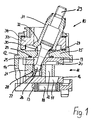
- the water valve 10 has a disk package consisting of three individual disks, which is enclosed by a housing 12 with a bottom 13, a side wall 14 and a cover 15.
- the lower disk 16 of the control element 11 is fixed against the housing base 12 and has openings 17 for the passage of the cold and warm water which flows into the valve via correspondingly assigned passage openings 18 in the housing base 13; only one opening 17, 18 can be seen in the figures.
- the valve is shown in the open position, in which the right edge of the movable disc is shifted relative to the associated edges of the fixed discs 16, 19, so that the water flowing into the water valve 10 from below through the openings 17 and the opening 22 and the deflection chamber 20 can flow into the water space of the valve. If the movable disk 21 is shifted to the right until the disk edges come to cover, the closed position of the water valve is reached, in which the deflection chambers 20 are constantly under the pressure of the water present on the valve.
- an actuating member 23 is provided which extends through the housing cover 15 in an opening 24 and the upper fixed disc 19 in an associated opening 25 and engages with a spherical guide 26 in the movable disc 21, which leads to the latter Purpose has a bore 28 into which a sleeve 27 is inserted for receiving the spherical guide 26 of the actuator 23.
- the actuating member 23 is essentially rod-shaped with a smaller diameter in the area of the through openings 24, 25 in the fixed upper disk 19 or the housing cover 15 and with a larger diameter in the area located outside the housing 12.
- the upper disc 19 is against the underside of the housing cover 15 is still sealed by means of a seal 29 surrounding the corresponding passage opening 25, so that no water can escape from the housing 12 through the opening 24 from the water space of the valve via the separating surface between the control element 11 and the underside of the housing cover 15.
- bearing points 30 are formed on the upper side of the cover 15, which in their cross-sectional representation in the figures have the shape of spherical sections.
- this is a half-cylinder which is placed with its cut surface on the cover 15 and has an opening for the passage of the actuating member 23.
- the dome-like spherical sections 30 are overlapped by lugs 32 of a sleeve 31, which in turn is connected to the actuating element 23; the relevant approaches 32 here have a surface of their inside which is matched to the outer shape of the bearing points 30.
- the side walls 14 of the housing 12 are extended above the cover 15 upwards, so that there is a cup-shaped space enclosing the actuating member 23 with the sleeve 31, in which a holding part 34 is fixed via a suitable connection, which in turn the lugs 32 of the sleeve 31 engages and thus defines the actuator 23 with the sleeve 31 axially in the valve 10.
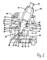
- FIG. 2 an embodiment is shown, which corresponds in its representation to the previously described embodiment, but in this embodiment the actuating member 23 in the plane of the housing cover 15 has a spherical thickening 35 filling the through opening 24, by means of which the guidance of the actuating member is improved and an additional axial securing against an axial displacement of the actuating member 23 is effected.
- an additional seal 36 which includes the spherical thickening 35 of the actuating member 23, is inserted into the inner wall of the recess 24.
Landscapes
- Engineering & Computer Science (AREA)
- General Engineering & Computer Science (AREA)
- Mechanical Engineering (AREA)
- Multiple-Way Valves (AREA)
- Motorcycle And Bicycle Frame (AREA)
- Toilet Supplies (AREA)
- External Artificial Organs (AREA)
- Mechanically-Actuated Valves (AREA)
- Bidet-Like Cleaning Device And Other Flush Toilet Accessories (AREA)
- Infusion, Injection, And Reservoir Apparatuses (AREA)
- Domestic Plumbing Installations (AREA)
- Electrically Driven Valve-Operating Means (AREA)
- Toys (AREA)
- Dental Preparations (AREA)
- Pharmaceuticals Containing Other Organic And Inorganic Compounds (AREA)
Description
- Die Erfindung betrifft ein sanitäres Wasserventil mit einem aus drei übereinander liegenden Steuerscheiben bestehenden und von einem Gehäuse umschlossenen Steuerelement, wobei die untere und die obere Steuerscheibe feststehen und die mittlere Steuerscheibe über ein an ihr angreifendes Betätigungsorgan relativ zu den festen Steuerscheiben verschiebbar ist, wobei das in zwei Ebenen im Gehäuse kipp- bzw. schwenkbar angeordnete Betätigungsorgan den Gehäusedeckel und die obere feste Steuerscheibe durchgreift.
- Ein Wasserventil mit den gattungsgemäßen Merkmalen ist in der DE-OS 35 25 053.4 beschrieben; dieses Wasserventil weist als Besonderheit ein aus drei Scheiben bestehendes Steuerelement auf, dessen mittlere Scheibe als bewegliche Steuerscheibe gegenüber den beiden äußeren festen Steuerscheiben relativ verschiebbar ist. Die Verschiebung der mittleren Steuerscheibeund damit die Regelung des Wasserstromes wird vorgenommen über ein Betätigungsorgan, das in die mittlere Steuerscheibe eingreift und mit dieser verbunden ist und dazu sowohl den Deckel des das Steuerelement umschließenden Gehäuses als auch die obere feststehende Steuerscheibe in jeweils einer entsprechend angeordneten Durchbrechung durchgreift. Bei dem bekannten Wasserventil ist das Betätigungsorgan mittels einer an ihm ausgebildeten und in der Durchbrechung der oberen feststehenden Steuerscheibe liegenden kugelförmigen Erweiterung gelagert.
- Hiermit ist der Nachteil verbunden, daß aufgrund der beengten Abmessungen der oberen feststehenden Steuerscheibe nur ein sehr kleiner Radius für die von der oberen Steuerscheibe aufzunehmende Lagerkugel ausgebildet werden kann. Die damit verbundenen engen Fertigungstoleranzen sind aber in einer Serienfertigung größerer Stückzahlen von Wasserventilen kaum einzuhalten, und zusätzlich sind die bei kleinem Kugelradius zur Verfügung stehenden Lagerflächen für das Betätigungsorgan in der oberen Scheibe so knapp bemessen, daß sich kaum eine ausreichende Stabilität der Lagerung des Betätigungsorgans in der oberen Scheibe sowie der Führung der mittleren beweglichen Scheibe über das Betätigungsorgan ergibt.
- Im Hinblick auf die Vermeidung derartiger Nachteile ist es beispielsweise aus der DE-OS 34 19 208 bekannt, bei einem zwei Scheiben umfassenden Ventil, bei welchem das Betätigungsorgan an der oberen beweglichen Scheibe angreift, das Betätigungsorgan mit einer Lagerkugel vergleichsweise großen Durchmessers in dem entsprechend stark ausgebildeten Deckelteil des Gehäuses zu lagern. Eine derartige Lösung ist aber auf ein gattungsgemäßes Wasserventil nicht anwendbar, weil aufgrund der zusätzlichen dritten Steuerscheibe und bei einer entsprechend dicken Ausbildung des Gehäusedeckels zur Aufnahme einer Lagerkugel größeren Durchmessers die Bauhöhe des Ventils insgesamt das zuträgliche Maß übersteigen würde.
- Der Erfindung liegt daher die Aufgabe zugrunde, ein Wasserventil mit den gattungsgemäßen Merkmalen so zu verbessern, daß seine Bauhöhe bei einer gleichzeitig einfach zu fertigenden und in ihrer Funktion wirkungsvollen Lagerung des Betätigungsorgans begrenzt ist.
- Die Lösung dieser Aufgabe ergibt sich einschließlich vorteilhafter Ausgestaltungen und Weiterbildungen aus dem Inhalt der Patentansprüche, welche dieser Beschreibung vorangestellt sind.
- Die Erfindung geht von dem Grundgedanken aus, daß das Betätigungsorgan an außerhalb des das Steuerelement umschließenden Gehäuses angeordneten Lagerstellen derart gelagert ist, daß der Drehpunkt des Betätigungsorgans in der Ebene des Gehäusedeckels liegt. Hiermit ist der wesentliche Vorteil verbunden, daß einerseits der Deckel des das Steuerelement umschließenden Gehäuses vergleichsweise dünn gehalten werden kann, weil er keine Lagerfunktion, sondern nur eine Durchtrittsfunktion für das Betätigungsorgan zu erfüllen hat; andererseits ergibt sich aber in vorteilhafter Weise ein kurz bemessener Abstand zwischen dem in der Ebene des Gehäusedeckels angeordneten Drehpunkt des Betätigungsorgans und dessen Verbindung mit der beweglichen Scheibe, was zur Folge hat, daß aufgrund des so gebildeten kurzen Hebelarms zwischen Drehpunkt und Angriffspunkt an der mittleren Scheibe und des längeren Hebelaarms zwischen Drehpunkt und der am oberen Ende des Betätigungsorgans ausgebildeten Handhabe eine größere Schwenkbewegung des Handhebels nur zu einer vergleichsweise geringen Verschiebung der beweglichen Scheibe führt, so daß eine Feineinstellung der Wasserwege möglich ist. Dieser Gesichtspunkt ist bei dem gattungsgemäßen Ventil deshalb von großer Bedeutung, weil aufgrund der in zwei Ebenen möglichen Wasseraustritte der Wasserdurchfluß durch das Ventil sehr viel größer ist als bei einem Zwei-Scheiben-Ventil, so daß bereits geringfügige Verschiebungen der beweglichen Steuerscherbe vergleichsweise große Auswirkungen auf die insgesamt das Ventil durchströmende Wassermenge haben.
- Nach einem bevorzugten Ausführungsbeispiel ist vorgesehen, daß sich auf dem Gehäusedeckel erhebend kugelabschnittförmige Lagerstellen angeordnet sind, die von einer mit dem Betätigungsorgan verbundenen Hülse formschlüssig derart umgriffen werden, daß sich eine Lagerung des Betätigungsorgans über die an ihm ausgebildete Hülse im Zusammenwirken mit den auf dem Gehäusedeckel angeordneten Lagerstellen ergibt. Nach einem Ausführungsbeispiel der Erfindung sind diese Lagerstellen als ein halbzylindrischer Körper ausgebildet, welcher mit seiner Schnittfläche senkrecht zur Schwenkebene des Betätigungsorgans auf den Deckel des Gehäuses gelegt ist und eine Öffnung zum Durchtritt des Betätigungsorgans aufweist; hierzu passend weist die Hülse den Halbzylinder übergreifende Ansätze auf, so daß hier eine Gleitlagerung auf einem Zylinderabschnitt verwirklicht ist.
- Nach einem Ausführungsbeispiel der Erfindung weist das Betätigungsorgan in der Ebene des Gehäusedeckels eine die Durchtrittsöffnung durch den Gehäusedeckel ausfüllende kugelartige Verdickung auf, die eine zusätzliche Führung und Sicherung des Betätigungsorgans gegen Zugbelastung bildet; diese kugelförmige Verdickung weist aber keine Lagerfunktion für das Betätigungsorgan auf.
- Nach der Erfindung kann ferner vorgesehen sein, das Betätigungsorgan mit Hülse durch ein am Gehäuse festzulegendes Halteteil zu sichern, so daß das Betätigungsorgan mit Hülse bezüglich der Lagerstellen fixiert ist.
- In der Zeichnung sind zwei Ausführungsbeispiele der Erfindung wiedergegeben, welche nachstehend beschrieben sind. Es zeigen:
- Fig. 1 ein sanitäres Wasserventil im Schnitt,
- Fig. 2 ein anderes Ausführungsbeispiel des Wasserventils gemäß Figur 1.
- Das Wasserventil 10 weist als Steuerelement 11 ein aus drei einzelnen Scheiben bestehendes Scheibenpaket auf, welches von einem Gehäuse 12 mit einem Boden 13, einer Seitenwandung 14 und einem Deckel 15 umschlossen ist. Die untere Scheibe 16 des Steuerelementes 11 ist gegen den Gehäuseboden 12 festgelegt und weist Öffnungen 17 zum Durchtritt des kalten und warmen Wassers auf, welches über entsprechend zugeordnete Durchtrittsöffnungen 18 in dem Gehäuseboden 13 in das Ventil einströmt; in den Figuren ist jeweils nur eine Öffnung 17, 18 erkennbar.
- Gegen den oberen Gehäusedeckel 15 festgelegt ist die obere Scheibe 19 des Steuerelementes 11, welche den Öffnungen 17, 18 zugeordnete Umlenkkammern 20 aufweist; zwischen den festen Scheiben 16, 19 ist die bewegliche Scheibe 21 mit entsprechend kommunizierenden Öffnungen 22 angeordnet, wie sich aus der Figurendarstellung ergibt. In den Figuren ist das Ventil jeweils in der Offenstellung eingezeichnet, bei welchem der rechte Rand der beweglichen Scheibe gegenüber den zugeordneten Rändern der festen Scheiben 16, 19 verschoben ist, so daß das von unten her in das Wasserventil 10 einströmende Wasser über die Öffnungen 17 bzw. die Öffnung 22 und die Umlenkkammer 20 in den Wasserraum des Ventils strömen kann. Wird die bewegliche Scheibe 21 nach rechts verschoben, bis die Scheibenränder zur Deckung gelangen, ist die geschlossene Stellung des Wasserventils erreicht, in welcher die Umlenkkammern 20 ständig unter dem Druck des auf dem Ventil anstehenden Wassers stehen.
- Zur Bewegung und Verschiebung der beweglichen Scheibe 21 ist ein Betätigungsorgan 23 vorgesehen, welches den Gehäusedeckel 15 in einer Öffnung 24 und die obere feste Scheibe 19 in einer zugeordneten Öffnung 25 durchgreift und mit einer kugelförmigen Führung 26 in die bewegliche Scheibe 21 eingreift, die zu diesem Zweck eine Bohrung 28 aufweist, in welche eine Hülse 27 zur Aufnahme der kugelförmigen Führung 26 des Betätigungsorgans 23 eingesetzt ist. Das Betätigungsorgan 23 ist im wesentlicher stabförmig ausgebildet mit einem geringeren Durchmesser im Bereich der Durchgriffsöffnungen 24, 25 in der festen oberen Scheibe 19 bzw. dem Gehäusedeckel 15 und mit einem größeren Durchmesser in dem außerhalb des Gehäuses 12 gelegenen Bereich. Die obere Scheibe 19 ist gegen die Unterseite des Gehäusedeckels 15 noch mittels einer die entsprechende Durchtrittsöffnung 25 umgebenden Dichtung 29 abgedichtet, so daß aus den Waasserraum des Ventils über die Trennfläche zwischen Steuerelement 11 und der Unterseite des Gehäusedeckels 15 kein Wasser über die Öffnung 24 aus dem Gehäuse 12 austreten kann.
- Zur Lagerung des Betätigungsorgans 23 sind auf der Oberseite des Deckels 15 sich erhebend Lagerstellen 30 ausgebildet, die in ihrer Querschnittsdarstellung in den Figuren die Form von Kugelabschnitten aufweisen. In der senkrecht zu der aus der Schnittdarstellung sich ergebenden Bewegungsebene des Betätigungsorgans 23 einstellenden Ebene des Ventils handelt es sich dabei um einen Halbzylinder, der mit seiner Schnittfläche auf den Deckel 15 aufgelegt ist und eine Öffnung zum Durchtritt des Betätigungsorgans 23 aufweist.
- Die sich domartig erhebenden Kugelabschnitte 30 werden übergriffen von Ansätzen 32 einer Hülse 31, die ihrerseits mit dem Betätigungselement 23 verbunden ist; die diesbezüglichen Ansätze 32 weisen hierbei eine auf die äußere Form der Lagerstellen 30 abgestimmte Oberfläche ihrer Innenseite auf.
- Die Seitenwände 14 des Gehäuses 12 sind über den Deckel 15 hinaus nach oben verlängert, so daß sich ein das Betätigungsorgan 23 mit Hülse 31 umschließender napfförmiger Raum ergibt, in welchem ein Halteteil 34 über eine geeignete Verbindung festgelegt ist, welches seinerseits die Ansätze 32 der Hülse 31 übergreift und somit das Betätigungsorgan 23 mit Hülse 31 axial in dem Ventil 10 festlegt.
- In Figur 2 ist ein Ausführungsbeispiel dargestellt, welches in seiner Darstellung dem zuvor beschriebenen Ausführungsbeispiel entspricht, jedoch weist bei dieser Ausführungsform das Betätigungsorgan 23 in der Ebene des Gehäusedeckels 15 eine die Durchtrittsöffnung 24 ausfüllende kugelartige Verdickung 35 auf, mittels welcher die Führung des Betätigungsorgans verbessert und eine zusätzliche Axialsicherung gegen eine axiale Verschiebung des Betätigungsorgans 23 bewirkt ist. Zusammenwirkend damit ist in die innere Wandung der Ausnehmung 24 eine zusätzliche, die kugelförmige Verdickung 35 des Betätigungsorgans 23 einschließende Dichtung 36 eingelegt.
Claims (9)
- Sanitäres Wasserventil (10) mit einem aus drei übereinander liegenden Steuerscheiben (16, 21, 19) bestehenden und von einem Gehäuse (12) umschlossenen Steuerelement (11), wobei die untere (16) und die obere (19) Steuerscheibe feststehen und die mittlere Steuerscheibe (21) über ein an ihr angreifendes Betätigungsorgan (23) relativ zu den festen Steuerscheiben verschiebbar ist, wobei das in zwei Ebenen im Gehäuse (12) kipp- beziehungsweise schwenkbar gelagerte Betätigungsorgan (23) den Gehäusedeckel (15) und die obere feste Steuerscheibe (19) durchgreift, dadurch gekennzeichnet, daß das Betätigungsorgan (23) an außerhalb des das Steuerelement (11) umschließenden Gehäuses (12) angeordneten Lagerstellen (30) derart gelagert ist, daß der Drehpunkt des Betätigungsorgans (23) in der Ebene des Gehäusedeckels (15) liegt.
- Wasserventil nach Anspruch 1, dadurch gekennzeichnet, daß die Lagerstellen (30) für das Betätigungsorgan (23) auf dem Gehäusedeckel (15) beiderseits der Schwenkebene des Betätigungsorgans (23) sich erhebend angeordnet sind.
- Wasserventil nach Anspruch 1 oder 2, dadurch gekennzeichnet, daß die Lagerstellen (30) als domartig sich auf dem Gehäusedeckel (15) erhebende Kugelabschnitte (30) ausgebildet sind.
- Wasserventil nach Anspruch 3, dadurch gekennzeichnet, daß als Lagerstelle ein senkrecht zur Schwenkebene des Betätigungsorgans (23) verlaufender und mit seiner Schnittfläche auf dem Gehäusedeckel (15) aufliegender Halbzylinder (30) angeordnet ist, der eine Öffnung zum Durchtritt des Betätigungsorgans (23) aufweist.
- Wasserventil nach einem der Ansprüche 1 bis 4, dadurch gekennzeichnet, daß das Betätigungsorgan (23) von einer die Lagerstellen (30) umfassenden Hülse (31) umgeben und mit dieser verbunden ist.
- Sanitäres Wasserventil nach Anspruch 5, dadurch gekennzeichnet, daß die Hülse (31) der Form der Lagerstellen (30) entsprechende und diese umgreifende Ansätze (32) aufweist.
- Wasserventil nach einem der Ansprüche 1 bis 6, dadurch gekennzeichnet, daß das Betätigungsorgan (23) in der Ebene des Gehäusedeckels (15) eine die Durchtrittsöffnung (24) ausfüllende kugelartige Verdickung (35) aufweist.
- Wasserventil nach einem der Ansprüche 1 bis 7, dadurch gekennzeichnet, daß in dem oberen napfförmigen Teil (33) des Gehäuses ein die Hülse (31) festlegendes Halteteil (34) angeordnet ist.
- Wasserventil nach einem der Ansprüche 1 bis 7, dadurch gekennzeichnet, daß die obere feste Scheibe (19) über einen die Durchtrittsöffnung (25) für das Betätigungsorgan (23) umschließenden Dichtungsring (29) gegen den Gehäusedeckel (15) abgedichtet ist.
Priority Applications (1)
| Application Number | Priority Date | Filing Date | Title |
|---|---|---|---|
| AT89912402T ATE86018T1 (de) | 1988-11-16 | 1989-11-16 | Sanitaeres wasserventil mit betaetigungsmechanik. |
Applications Claiming Priority (2)
| Application Number | Priority Date | Filing Date | Title |
|---|---|---|---|
| DE3838765 | 1988-11-16 | ||
| DE3838765A DE3838765A1 (de) | 1988-11-16 | 1988-11-16 | Sanitaeres wasserventil mit betaetigungsmechanik |
Publications (2)
| Publication Number | Publication Date |
|---|---|
| EP0444064A1 EP0444064A1 (de) | 1991-09-04 |
| EP0444064B1 true EP0444064B1 (de) | 1993-02-24 |
Family
ID=6367259
Family Applications (1)
| Application Number | Title | Priority Date | Filing Date |
|---|---|---|---|
| EP89912402A Expired - Lifetime EP0444064B1 (de) | 1988-11-16 | 1989-11-16 | Sanitäres wasserventil mit betätigungsmechanik |
Country Status (10)
| Country | Link |
|---|---|
| US (1) | US5144981A (de) |
| EP (1) | EP0444064B1 (de) |
| JP (1) | JPH0781649B2 (de) |
| AT (1) | ATE86018T1 (de) |
| AU (1) | AU4516789A (de) |
| BR (1) | BR8907855A (de) |
| CA (1) | CA2003068A1 (de) |
| DE (3) | DE3838765A1 (de) |
| ES (1) | ES2039954T3 (de) |
| WO (1) | WO1990005868A1 (de) |
Families Citing this family (10)
| Publication number | Priority date | Publication date | Assignee | Title |
|---|---|---|---|---|
| IT1260746B (it) * | 1992-04-30 | 1996-04-22 | Orlando Bosio | Dispositivo limitatore della portata in cartuccia miscelatrice monocomando per acqua calda e fredda |
| DE4308746A1 (de) * | 1993-03-19 | 1994-09-22 | Sanha Kaimer Kg | Einhebelmischbatterie |
| US5573037A (en) * | 1995-11-27 | 1996-11-12 | George S. Cole & Associates, Incorporated | Faucet valve with external cam and pinch tubes |
| HU223929B1 (hu) * | 1997-04-04 | 2005-03-29 | KEROX-MULTIPOLÁR II. Kft. | Gömbpálya vezérlésű síktárcsás keverő csaptelepbetét |
| JP2004530846A (ja) * | 2001-04-18 | 2004-10-07 | フィッシャー コントロールズ インターナショナル リミテッド ライアビリティー カンパニー | ピボット作動型スリーブバルブ |
| US8978700B2 (en) * | 2007-01-31 | 2015-03-17 | Moen Incorporated | Valve cartridge with improved flow rate |
| DE102008018508A1 (de) | 2008-04-10 | 2009-10-22 | Ideal-Standard International B.V.B.A. | Sanitärarmatur |
| EP2110586B1 (de) | 2008-04-15 | 2011-11-30 | Kwc Ag | Sanitärarmatur mit separater Lagerung des Betätigungshebels |
| EP2317193A1 (de) | 2009-10-20 | 2011-05-04 | Kwc Ag | Sanitärarmatur mit verschiebbar gelagtertem Betätigungshebel |
| US11846367B2 (en) * | 2019-04-05 | 2023-12-19 | Takagi Co., Ltd. | Mixer faucet |
Citations (2)
| Publication number | Priority date | Publication date | Assignee | Title |
|---|---|---|---|---|
| DE3419208A1 (de) * | 1984-05-23 | 1985-11-28 | Hans Grohe Gmbh & Co Kg, 7622 Schiltach | Steuereinsatz fuer sanitaere mischarmaturen |
| DE3525053A1 (de) * | 1985-07-13 | 1987-01-22 | Ideal Standard | Sanitaeres ventil |
Family Cites Families (12)
| Publication number | Priority date | Publication date | Assignee | Title |
|---|---|---|---|---|
| US3324884A (en) * | 1963-07-02 | 1967-06-13 | Price Pfister Brass Mfg Compan | Single-handled valve structure |
| US3372710A (en) * | 1966-03-17 | 1968-03-12 | Larry J. Miller | Single handle faucet valve |
| US3415281A (en) * | 1965-08-11 | 1968-12-10 | Nile Corp | Valves |
| US3533444A (en) * | 1968-05-01 | 1970-10-13 | Price Pfister Brass Mfg | Low noise level valve structure |
| US3526250A (en) * | 1969-06-02 | 1970-09-01 | Larry J Miller | Single handle faucet valve |
| US3667503A (en) * | 1970-06-05 | 1972-06-06 | Elkay Mfg Co | Single-handle mixing and proportioning valve |
| US3882897A (en) * | 1973-08-13 | 1975-05-13 | Masco Corp | Mixing valve |
| IT7621837U1 (it) * | 1976-07-26 | 1978-01-26 | Zucchetti Rubinetteria Spa | Miscelatore per acqua calda e fredda. |
| US4162169A (en) * | 1977-12-21 | 1979-07-24 | The United States Of America As Represented By The Administrator Of The National Aeronautics And Space Administration | Alkali-metal silicate binders and methods of manufacture |
| US4378029A (en) * | 1981-11-02 | 1983-03-29 | American Standard Inc. | Single control faucet |
| IT1213318B (it) * | 1986-07-31 | 1989-12-20 | Stella Rubinetterie Spa | Rubinetto miscelatore per acqua del tipo monocomando, con mezzi, di regolazione fine della temperatura di mescelazione. |
| NZ226658A (en) * | 1987-10-27 | 1990-03-27 | Dorf Ind Pty Ltd | Single handle mixing valve including apertured discs |
-
1988
- 1988-11-16 DE DE3838765A patent/DE3838765A1/de not_active Withdrawn
-
1989
- 1989-11-15 CA CA002003068A patent/CA2003068A1/en not_active Abandoned
- 1989-11-16 DE DE8989912402T patent/DE58903616D1/de not_active Expired - Fee Related
- 1989-11-16 ES ES198989912402T patent/ES2039954T3/es not_active Expired - Lifetime
- 1989-11-16 EP EP89912402A patent/EP0444064B1/de not_active Expired - Lifetime
- 1989-11-16 US US07/679,041 patent/US5144981A/en not_active Expired - Lifetime
- 1989-11-16 WO PCT/DE1989/000719 patent/WO1990005868A1/de not_active Ceased
- 1989-11-16 JP JP1511631A patent/JPH0781649B2/ja not_active Expired - Fee Related
- 1989-11-16 AU AU45167/89A patent/AU4516789A/en not_active Abandoned
- 1989-11-16 AT AT89912402T patent/ATE86018T1/de not_active IP Right Cessation
- 1989-11-16 BR BR898907855A patent/BR8907855A/pt not_active IP Right Cessation
- 1989-11-16 DE DE89DE8900719A patent/DE3991336D2/de not_active Expired - Fee Related
Patent Citations (2)
| Publication number | Priority date | Publication date | Assignee | Title |
|---|---|---|---|---|
| DE3419208A1 (de) * | 1984-05-23 | 1985-11-28 | Hans Grohe Gmbh & Co Kg, 7622 Schiltach | Steuereinsatz fuer sanitaere mischarmaturen |
| DE3525053A1 (de) * | 1985-07-13 | 1987-01-22 | Ideal Standard | Sanitaeres ventil |
Also Published As
| Publication number | Publication date |
|---|---|
| AU4516789A (en) | 1990-06-12 |
| JPH0781649B2 (ja) | 1995-09-06 |
| BR8907855A (pt) | 1991-10-08 |
| ATE86018T1 (de) | 1993-03-15 |
| ES2039954T3 (es) | 1993-10-01 |
| US5144981A (en) | 1992-09-08 |
| DE3991336D2 (en) | 1991-11-21 |
| DE3838765A1 (de) | 1990-05-23 |
| DE3991336A1 (en) | 1991-11-21 |
| CA2003068A1 (en) | 1990-05-16 |
| EP0444064A1 (de) | 1991-09-04 |
| JPH06506282A (ja) | 1994-07-14 |
| DE58903616D1 (de) | 1993-04-01 |
| WO1990005868A1 (de) | 1990-05-31 |
Similar Documents
| Publication | Publication Date | Title |
|---|---|---|
| DE69310261T2 (de) | Proportionales, elektromagnetisch gesteuertes Ventil | |
| EP0238674B1 (de) | Sanitäre Mischbatterie | |
| EP0444064B1 (de) | Sanitäres wasserventil mit betätigungsmechanik | |
| DE10394005T5 (de) | Pendelventil-Baugruppe | |
| DE19810391A1 (de) | Druckreduzierventil | |
| EP1250533A1 (de) | Hydropneumatischer druckspeicher | |
| DE2549830A1 (de) | Membranventil | |
| DE2816806C2 (de) | Ventil | |
| DE3441251A1 (de) | Ventil fuer leicht verdampfbare fluessigkeiten, insbesondere expansionsventil fuer kaelteanlagen | |
| AT519932A2 (de) | Ablassventil für hohe Drücke | |
| DE102007011047A1 (de) | Magnetventilinjektor | |
| DE2542663A1 (de) | Wasserauslaufarmatur | |
| DE3830700A1 (de) | Wassermischventil | |
| EP0222858B1 (de) | Rohrtrenner | |
| DE29880034U1 (de) | Wasserhahnkartusche mit einem planen Verschlußelement | |
| DE3619840C2 (de) | Gashahn | |
| DE1961248A1 (de) | Ventil | |
| DE3740144C2 (de) | ||
| EP0046162B1 (de) | Einhebelmischventil zur Steuerung eines Wasserstromes | |
| DE3342951A1 (de) | Betaetigungseinrichtung fuer zwei abhaengig voneinander betaetigbare ventile | |
| DE19815754A1 (de) | Schwimmergesteuertes Servoventil | |
| DE3340166C2 (de) | ||
| DE3414548C2 (de) | ||
| DE2244443A1 (de) | Schaltventil fuer die ueberwachung der verbindung eines arbeitszylinders mit einem vorratsbehaelter | |
| DE2350553C3 (de) | Mischventil |
Legal Events
| Date | Code | Title | Description |
|---|---|---|---|
| PUAI | Public reference made under article 153(3) epc to a published international application that has entered the european phase |
Free format text: ORIGINAL CODE: 0009012 |
|
| AK | Designated contracting states |
Kind code of ref document: A1 Designated state(s): AT BE DE ES FR GB IT NL |
|
| 17P | Request for examination filed |
Effective date: 19910510 |
|
| 17Q | First examination report despatched |
Effective date: 19920511 |
|
| GRAA | (expected) grant |
Free format text: ORIGINAL CODE: 0009210 |
|
| AK | Designated contracting states |
Kind code of ref document: B1 Designated state(s): AT BE DE ES FR GB IT NL |
|
| PG25 | Lapsed in a contracting state [announced via postgrant information from national office to epo] |
Ref country code: IT Free format text: LAPSE BECAUSE OF FAILURE TO SUBMIT A TRANSLATION OF THE DESCRIPTION OR TO PAY THE FEE WITHIN THE PRESCRIBED TIME-LIMIT;WARNING: LAPSES OF ITALIAN PATENTS WITH EFFECTIVE DATE BEFORE 2007 MAY HAVE OCCURRED AT ANY TIME BEFORE 2007. THE CORRECT EFFECTIVE DATE MAY BE DIFFERENT FROM THE ONE RECORDED. Effective date: 19930224 |
|
| REF | Corresponds to: |
Ref document number: 86018 Country of ref document: AT Date of ref document: 19930315 Kind code of ref document: T |
|
| REF | Corresponds to: |
Ref document number: 58903616 Country of ref document: DE Date of ref document: 19930401 |
|
| ET | Fr: translation filed | ||
| GBT | Gb: translation of ep patent filed (gb section 77(6)(a)/1977) |
Effective date: 19930527 |
|
| REG | Reference to a national code |
Ref country code: ES Ref legal event code: FG2A Ref document number: 2039954 Country of ref document: ES Kind code of ref document: T3 |
|
| PLBE | No opposition filed within time limit |
Free format text: ORIGINAL CODE: 0009261 |
|
| STAA | Information on the status of an ep patent application or granted ep patent |
Free format text: STATUS: NO OPPOSITION FILED WITHIN TIME LIMIT |
|
| 26N | No opposition filed | ||
| PGFP | Annual fee paid to national office [announced via postgrant information from national office to epo] |
Ref country code: NL Payment date: 19941130 Year of fee payment: 6 |
|
| PG25 | Lapsed in a contracting state [announced via postgrant information from national office to epo] |
Ref country code: NL Effective date: 19960601 |
|
| NLV4 | Nl: lapsed or anulled due to non-payment of the annual fee |
Effective date: 19960601 |
|
| REG | Reference to a national code |
Ref country code: GB Ref legal event code: IF02 |
|
| PGFP | Annual fee paid to national office [announced via postgrant information from national office to epo] |
Ref country code: ES Payment date: 20051122 Year of fee payment: 17 |
|
| PGFP | Annual fee paid to national office [announced via postgrant information from national office to epo] |
Ref country code: AT Payment date: 20061102 Year of fee payment: 18 |
|
| PGFP | Annual fee paid to national office [announced via postgrant information from national office to epo] |
Ref country code: FR Payment date: 20061117 Year of fee payment: 18 |
|
| PGFP | Annual fee paid to national office [announced via postgrant information from national office to epo] |
Ref country code: GB Payment date: 20061122 Year of fee payment: 18 |
|
| PGFP | Annual fee paid to national office [announced via postgrant information from national office to epo] |
Ref country code: BE Payment date: 20061220 Year of fee payment: 18 |
|
| PGFP | Annual fee paid to national office [announced via postgrant information from national office to epo] |
Ref country code: DE Payment date: 20070102 Year of fee payment: 18 |
|
| REG | Reference to a national code |
Ref country code: ES Ref legal event code: FD2A Effective date: 20061117 |
|
| PG25 | Lapsed in a contracting state [announced via postgrant information from national office to epo] |
Ref country code: ES Free format text: LAPSE BECAUSE OF NON-PAYMENT OF DUE FEES Effective date: 20061117 |
|
| BERE | Be: lapsed |
Owner name: *IDEAL-STANDARD G.M.B.H. Effective date: 20071130 |
|
| GBPC | Gb: european patent ceased through non-payment of renewal fee |
Effective date: 20071116 |
|
| PG25 | Lapsed in a contracting state [announced via postgrant information from national office to epo] |
Ref country code: AT Free format text: LAPSE BECAUSE OF NON-PAYMENT OF DUE FEES Effective date: 20071116 |
|
| PG25 | Lapsed in a contracting state [announced via postgrant information from national office to epo] |
Ref country code: BE Free format text: LAPSE BECAUSE OF NON-PAYMENT OF DUE FEES Effective date: 20071130 |
|
| PG25 | Lapsed in a contracting state [announced via postgrant information from national office to epo] |
Ref country code: DE Free format text: LAPSE BECAUSE OF NON-PAYMENT OF DUE FEES Effective date: 20080603 |
|
| REG | Reference to a national code |
Ref country code: FR Ref legal event code: ST Effective date: 20080930 |
|
| PG25 | Lapsed in a contracting state [announced via postgrant information from national office to epo] |
Ref country code: GB Free format text: LAPSE BECAUSE OF NON-PAYMENT OF DUE FEES Effective date: 20071116 |
|
| PG25 | Lapsed in a contracting state [announced via postgrant information from national office to epo] |
Ref country code: FR Free format text: LAPSE BECAUSE OF NON-PAYMENT OF DUE FEES Effective date: 20071130 |