EP0443662A2 - Rotating spray arm arrangement for dishwasher - Google Patents
Rotating spray arm arrangement for dishwasher Download PDFInfo
- Publication number
- EP0443662A2 EP0443662A2 EP91200285A EP91200285A EP0443662A2 EP 0443662 A2 EP0443662 A2 EP 0443662A2 EP 91200285 A EP91200285 A EP 91200285A EP 91200285 A EP91200285 A EP 91200285A EP 0443662 A2 EP0443662 A2 EP 0443662A2
- Authority
- EP
- European Patent Office
- Prior art keywords
- sealing ring
- rotor
- support tube
- cylinder part
- spray arm
- Prior art date
- Legal status (The legal status is an assumption and is not a legal conclusion. Google has not performed a legal analysis and makes no representation as to the accuracy of the status listed.)
- Granted
Links
Images

Classifications
-
- A—HUMAN NECESSITIES
- A47—FURNITURE; DOMESTIC ARTICLES OR APPLIANCES; COFFEE MILLS; SPICE MILLS; SUCTION CLEANERS IN GENERAL
- A47L—DOMESTIC WASHING OR CLEANING; SUCTION CLEANERS IN GENERAL
- A47L15/00—Washing or rinsing machines for crockery or tableware
- A47L15/14—Washing or rinsing machines for crockery or tableware with stationary crockery baskets and spraying devices within the cleaning chamber
- A47L15/18—Washing or rinsing machines for crockery or tableware with stationary crockery baskets and spraying devices within the cleaning chamber with movably-mounted spraying devices
- A47L15/22—Rotary spraying devices
- A47L15/23—Rotary spraying devices moved by means of the sprays
Definitions
- the invention relates to a spray arm mounting in a dishwasher with a stationary support tube for the supply of washing water, a rotor rotatably mounted on the support tube for distributing the washing water and with a sealing ring that seals a gap between the rotor and the support tube and that is rotationally fixed with a lateral surface abuts on a cylinder part of the rotor and with an end face on a sealing surface of the support tube lying parallel to the rotor plane.
- Such a design is such.
- B. become known from DE-PS 34 30 464.
- the rotor is rotatably mounted on a bearing journal which is fixedly connected to the support tube.
- the rotor plugged onto the trunnion is held by a nut screwed onto the free end of the trunnion, with play remaining between the nut and the top of the rotor, so that the rotor is rotatably supported on the trunnion and thus on the support tube.
- the cylinder part of the rotor surrounds the free end of the support tube to form a gap.
- a radially resilient slotted sealing ring lies with its outer lateral surface in a rotationally fixed manner on the inner lateral surface of the cylinder part and runs around in a sealing groove of the support tube.
- one or the other end face of the sealing ring on the associated partial surface of the sealing groove apply and thus forms a seal. If there is wear in the sealing areas, the sealing ring is automatically readjusted.
- the rotor is also rotatably mounted on a bearing journal connected to the support tube via a special bearing bush. With this type of construction too, the rotor is secured against loosening by a nut screwed onto the free end of the bearing journal.
- the inner cylinder part of the rotor is surrounded by the support tube to form a gap, a sealing ring being provided in the gap, which sits with its inner circumferential surface on the outer circumferential surface of the cylinder part and with its one end face a sealing surface with a union nut of the support tube.
- the invention has for its object to simplify and improve a spray arm mounting of the type mentioned in terms of its structure and assembly.
- This object is achieved according to the invention in that the rotor, for. B. via a blind hole and a bearing pin, is placed on the support tube, that the sealing ring is fixed in the axial direction of the rotor fixed to the cylinder part and that the rotor is secured by an attack on the sealing ring counter bearing of the support tube against loosening.
- the sealing ring takes over both the function of the seal and the function of the holder of the rotor
- a particularly simple and secure fastening of the sealing ring against axial displacements results from the fact that it is mounted in a circumferential annular groove of the cylinder part. This enables a particularly simple assembly of the sealing ring by snapping into the ring groove if the sealing ring is designed to be radially flexible and either slotted or closed.
- the rotationally fixed mounting of the sealing ring on the cylinder part generally prevents relative movement and thus wear between these two parts.
- a driver engaging in a clearance of the sealing ring can be provided.
- a relative and rotational movement between the rotor and the sealing ring is thus avoided in a simple and reliable manner, so that the cylinder part or the rotor remain wear-free. It is essential in the invention thus that in the normal case only axial sliding friction takes place between an end face of the sealing ring and part of the support tube, the support tube simultaneously forming the counter bearing with the holding function mentioned above.
- the sealing ring can be provided with bores running in the axial direction.
- a union nut which is screwed onto the free end of the support tube is preferably provided as a counter-bearing for the sealing ring fastened to the outer circumferential surface of the cylinder part, the end face of the sealing ring remote from the sealing surface being pressurized by the flushing water.
- the thread of the union nut and the support tube is replaced by a bayonet lock, the direction of rotation of the rotor can be set as desired without fear of loosening the union nut. This also makes assembly easier.
- a radially outwardly projecting, circumferential flange is provided at the end of the support tube as a counterbearing for the sealing ring fastened to the inner circumferential surface of the cylinder part Sealing ring forms.
- Both types enable simple assembly and require fewer components than the known types according to the prior art and prevent the passage of peeling water in the axle bearing area of the rotor.
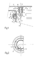
- FIG. 1 and 2 shows a support tube 10 fixedly attached to a dishwasher with an outer ring 11 and a centrally arranged bearing part 12 which is connected to the outer ring 11 via flanges 13.
- a bearing journal 14 is firmly injected into the bearing part 12, onto which a bearing bush 15 is placed.
- 16 with a rotor is designated, which has a centrally arranged hub 16a and two spray arms 17.
- the rotor 16 is through a blind hole drilled in the hub 16a 18 placed on the bearing pin 14 or the bearing bush 15.
- a cylinder part 19 attached to the lower end of the rotor 16 is surrounded by the outer ring 11 of the support tube 10, forming a gap 20.
- the cylinder part 19 has a circumferential annular groove 21, in which a radially resilient, slotted sealing ring 22 (piston ring) is embedded.
- the sealing ring 22 sits with its inner lateral surface 22a firmly on the bottom of the groove 21 of the cylinder part 19.
- a union nut 23 is screwed onto the outer end 11a of the outer ring 11 and forms a seal with an end face 23a with the end face 22b of the sealing ring.
- the union nut 23 also forms the counterbearing for the sealing ring 22 when the rotor 16 is pressed against the end face 23a of the union nut over the end face 22b of the sealing ring 22 when the rinsing water flows in in the direction 24. This prevents the rotor 16 from being detached from the support tube 10.
- a protruding driver 25 is provided in the groove 21, which engages in a recess 26 in the sealing ring 22.
- the assembly is carried out in a simple manner such that the rotor 16 is first provided with the bearing bush 15. Then the union nut 23 is pushed over the cylinder part 19 and the sealing ring 22 is embedded in the groove 21. Then this assembled unit comprising the rotor 16, the union nut 23 and the sealing ring 22 is pushed onto the bearing pin 14 of the rotor 16 via the blind hole 19 and then by means of the union nut 23 the ring part 11a screwed on. With 11b ribs for guiding the rinse water are designated.
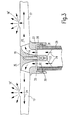
- the cylinder part 27 includes the support tube 29 to form a gap 28, the annular groove 30 for receiving and fastening the sealing ring 31 now being arranged on the inside of the cylinder part 27.
- the sealing ring 31 rotates in an annular sealing groove 32 in the support tube 29.
- the sealing groove 32 is delimited at the upper end by a radially outwardly projecting ring flange 33.
- This ring flange 33 forms a seal on the one hand with the end face of the sealing ring 31 facing it and, on the other hand, the counter bearing for the sealing ring 31 when the latter, together with the rotor 16, is pressed upward with the flushing water flowing in.
- the sealing ring 31 also assumes both a sealing and a holding function. Especially when the rinsing water flows in, the rotor 16 is pressed upward, whereby a loosening from the support tube 29 by the holding and sealing ring 31 is prevented. In the further course of operation, the pressure in the rotor 16 drops because water emerges from the spray openings 16 '. Since water penetrating through the gap 28 acts simultaneously on the sealing ring 31, the rotor 16 is now pressed down. In this case, there is a seal between the lower end face of the sealing ring 31 and the facing surface of the sealing groove 32.
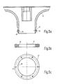
- FIG. 4a shows the cylindrical end 19 according to FIG. 1 with the annular groove 21 into which the sealing ring 34 according to FIG. 4b is to be introduced.
- the inner diameter of the sealing ring 34 is somewhat smaller than the diameter of the annular groove 21 on the groove base.
- the sealing ring 34 is pushed onto the cylinder part 19 until it snaps into the annular groove 21. This is possible because both parts are made of flexible plastic. After the process, the sealing ring 34 is firmly attached to the rotor with a press fit.
- the end of the cylinder part 19 is chamfered for insertion.
- FIGS. 5a again shows the cylinder part 19, the beveled parts of which are designed here as locking elements 36 resilient in the direction of the arrow 35.
- the sealing ring 37 shown in FIGS. 5b and c When the sealing ring 37 shown in FIGS. 5b and c is applied, the latching elements 36 yield to the inside and then snap back, so that the sealing ring 37 is clamped in place. Slipping is prevented by circumferential teeth 38 on the inner circumferential surface of the sealing ring 37. With 39 through holes in the sealing ring 37 are designated.
Landscapes
- Washing And Drying Of Tableware (AREA)
Abstract
Description
Die Erfindung bezieht sich auf eine Sprüharmlagerung bei einer Geschirrspülmaschine mit einem ortsfesten Tragrohr für die Zufuhr von Spülwasser, einem auf dem Tragrohr drehbar gelagerten Rotor zur Verteilung des Spülwassers und mit einem einen Spalt zwischen dem Rotor und dem Tragrohr abdichtenden Dichtungsring, der mit einer Mantelfläche drehfest an einem Zylinderteil des Rotors und mit einer Stirnseite an einer parallel zur Rotorebene liegenden Dichtfläche des Tragrohres anliegt.The invention relates to a spray arm mounting in a dishwasher with a stationary support tube for the supply of washing water, a rotor rotatably mounted on the support tube for distributing the washing water and with a sealing ring that seals a gap between the rotor and the support tube and that is rotationally fixed with a lateral surface abuts on a cylinder part of the rotor and with an end face on a sealing surface of the support tube lying parallel to the rotor plane.
Eine derartige Bauart ist z. B. durch die DE-PS 34 30 464 bekannt geworden. Bei der bekannten Bauart ist der Rotor drehbar auf einem mit dem Tragrohr fest verbundenen Lagerzapfen gelagert. Der auf den Lagerzapfen gesteckte Rotor wird durch eine auf das freie Ende des Lagerzapfen geschraubte Mutter gehalten, wobei zwischen der Mutter und der Oberseite des Rotors ein Spiel bestehen bleibt, so daß der Rotor drehbar auf dem Lagerzapfen und damit auf dem Tragrohr gelagert ist. Das Zylinderteil des Rotors umgibt das freie Ende des Tragrohres unter Bildung eines Spaltes. Ein radial federnder geschlitzter Dichtring liegt mit seiner äußeren Mantelfläche drehfest an der inneren Mantelfläche des Zylinderteiles an und läuft in einer Dichtnut des Tragrohres um. Je nach Größe des Wasserdruckes wird die eine oder die andere Stirnfläche des Dichtringes an der zugehörigen Teilfläche der Dichtnut anliegen und bildet somit eine Dichtung. Bei Verschleiß in den Dichtbereichen erfolgt eine selbsttätige Nachstellung des Dichtringes.Such a design is such. B. become known from DE-PS 34 30 464. In the known design, the rotor is rotatably mounted on a bearing journal which is fixedly connected to the support tube. The rotor plugged onto the trunnion is held by a nut screwed onto the free end of the trunnion, with play remaining between the nut and the top of the rotor, so that the rotor is rotatably supported on the trunnion and thus on the support tube. The cylinder part of the rotor surrounds the free end of the support tube to form a gap. A radially resilient slotted sealing ring lies with its outer lateral surface in a rotationally fixed manner on the inner lateral surface of the cylinder part and runs around in a sealing groove of the support tube. Depending on the size of the water pressure, one or the other end face of the sealing ring on the associated partial surface of the sealing groove apply and thus forms a seal. If there is wear in the sealing areas, the sealing ring is automatically readjusted.
Bei einer anderen, von der Anmelderin verwendeten ähnlichen Bauart ist der Rotor über eine besondere Lagerbuchse ebenfalls auf einem ortsfest mit dem Tragrohr verbundenen Lagerzapfen drehbar gelagert. Auch bei dieser Bauart wird der Rotor durch eine auf das freie Ende des Lagerzapfens geschraubte Mutter gegen Lösen gesichert. Bei dieser Bauart ist das innen liegende Zylinderteil des Rotors unter Bildung eines Spaltes von dem Tragrohr umgeben, wobei in dem Spalt ein Dichtring vorgesehen ist, der mit seiner inneren Mantelfläche auf der äußeren Mantelfläche des Zylinderteiles sitzt und mit seiner einen Stirnseite eine Dichtfläche mit einer Überwurfmutter des Tragrohres bildet.In another type of construction used by the applicant, the rotor is also rotatably mounted on a bearing journal connected to the support tube via a special bearing bush. With this type of construction too, the rotor is secured against loosening by a nut screwed onto the free end of the bearing journal. In this design, the inner cylinder part of the rotor is surrounded by the support tube to form a gap, a sealing ring being provided in the gap, which sits with its inner circumferential surface on the outer circumferential surface of the cylinder part and with its one end face a sealing surface with a union nut of the support tube.
Bei beiden bekannten Bauarten muß also der Rotor durch eine besondere, auf den Lagerzapfen geschraubte Mutter gegen Lösen gesichert werden.In both known types, the rotor must be secured against loosening by a special nut screwed onto the bearing journal.
Der Erfindung liegt die Aufgabe zugrunde, eine Sprüharmlagerung der eingangs genannten Art hinsichtlich ihres Aufbaues und ihrer Montage zu vereinfachen und zu verbessern. Diese Aufgabe wird gemäß der Erfindung dadurch gelöst, daß der Rotor, z. B. über eine Sacklochbohrung und einen Lagerzapfen, auf das Tragsrohr gesteckt wird, daß der Dichtungsring in Achsrichtung des Rotors unverstellbar an dem Zylinderteil befestigt ist und daß der Rotor durch ein am Dichtungsring angreifendes Gegenlager des Tragrohres gegen Lösen gesichert ist. Bei einer derartigen erfindungsgemäßen Ausbildung übernimmt der Dichtungsring sowohl die Funktion der Abdichtung als auch die Funktion der Halterung des RotorsThe invention has for its object to simplify and improve a spray arm mounting of the type mentioned in terms of its structure and assembly. This object is achieved according to the invention in that the rotor, for. B. via a blind hole and a bearing pin, is placed on the support tube, that the sealing ring is fixed in the axial direction of the rotor fixed to the cylinder part and that the rotor is secured by an attack on the sealing ring counter bearing of the support tube against loosening. With such a design according to the invention, the sealing ring takes over both the function of the seal and the function of the holder of the rotor
Durch die unverrückbare Befestigung des Dichtungsringes auf dem Zylinderteil des Rotors und durch das mit diesem Dichtungs- bzw. Haltering zusammenwirkende Gegenlager des Tragrohres wird der Rotor zuverlässig auf dem Lager des Tragrohres festgehalten, so daß eine bisher übliche besondere Befestigung des Rotors mit einer auf den Lagerzapfen des Tragrohres geschraubten Mutter entfallen kann. An der zum Spülraum hin geschlossenen Lagerstelle (Sacklochbohrung) kann somit auch kein Schälwasser mehr austreten. In Ausgestaltung der Erfindung ergibt sich eine besonders einfache und sichere Befestigung des Dichtringes gegen Axialverschiebungen dadurch, daß dieser in einer umlaufenden Ringnut des Zylinderteiles gelagert ist. Dies ermöglicht eine besonders einfache Montage des Dichtringes durch Einschnappen in die Ringnut, wenn der Dichtungsring radial nachgiebig ausgebildet und entweder geschlitzt oder geschlossen ausgebildet ist.Due to the immovable fastening of the sealing ring on the cylinder part of the rotor and through the counter bearing of the support tube interacting with this sealing or holding ring, the rotor is reliably held on the bearing of the support tube, so that a previously customary special attachment of the rotor with one on the bearing journal screwed nut of the support tube can be omitted. No more peeling water can escape at the storage area closed to the wash cabinet (blind hole). In an embodiment of the invention, a particularly simple and secure fastening of the sealing ring against axial displacements results from the fact that it is mounted in a circumferential annular groove of the cylinder part. This enables a particularly simple assembly of the sealing ring by snapping into the ring groove if the sealing ring is designed to be radially flexible and either slotted or closed.
Durch die drehfeste Lagerung des Dichtungsringes auf dem Zylinderteil wird eine Relativbewegung und damit ein Verschleiß zwischen diesen beiden Teilen im allgemeinen verhindert. Für den Fall, daß bei Verwendung eines radial federnden Dichtungsringes die Federspannung aus irgendwelchen Gründen nachläßt, kann in weiterer Ausgestaltung der Erfindung am Zylinder ein in eine Freisparung des Dichtungsringes eingreifender Mitnehmer vorgesehen sein. Damit wird auf einfache und zuverlässige Weise eine Relativ-Drehbewegung zwischen Rotor und Dichtungsring vermieden, so daß das Zylinderteil bzw. der Rotor verschleißfrei bleiben. Wesentlich bei der Erfindung ist somit, daß im Normalfall nur eine Axialgleitreibung zwischen einer Stirnseite des Dichtungsringes und einem Teil des Tragrohres stattfindet, wobei das Tragrohr gleichzeitig das Gegenlager mit der oben genannten Haltefunktion bildet.The rotationally fixed mounting of the sealing ring on the cylinder part generally prevents relative movement and thus wear between these two parts. In the event that the spring tension decreases for any reason when using a radially resilient sealing ring, in a further embodiment of the invention, a driver engaging in a clearance of the sealing ring can be provided. A relative and rotational movement between the rotor and the sealing ring is thus avoided in a simple and reliable manner, so that the cylinder part or the rotor remain wear-free. It is essential in the invention thus that in the normal case only axial sliding friction takes place between an end face of the sealing ring and part of the support tube, the support tube simultaneously forming the counter bearing with the holding function mentioned above.
Zur Erzeugung einer hydrodynamischen Schmierung kann der Dichtungsring mit in Achsrichtung verlaufenden Bohrungen versehen sein.To generate hydrodynamic lubrication, the sealing ring can be provided with bores running in the axial direction.
Bei einer Bauart mit innen liegendem Zylinderteil ist als Gegenlager für den auf der Außenmantelfläche des Zylinderteils befestigten Dichtungsring vorzugsweise eine auf das freie Ende des Tragrohres geschraubte Überwurfmutter vorgesehen, wobei die der Dichtfläche abgelegene Stirnseite des Dichtungsringes vom Spülwasser mit Druck beaufschlagbar ist. Wenn in Ausgestaltung der Erfindung das Gewinde der Überwurfmutter und des Tragrohres durch einen Bajonettverschluß ersetzt wird, kann die Rotordrehrichtung beliebig festgelegt werden, ohne ein Lösen der Überwurfmutter befürchten zu müssen. Ferner wird dadurch die Montage erleichtert.In the case of a design with an internal cylinder part, a union nut which is screwed onto the free end of the support tube is preferably provided as a counter-bearing for the sealing ring fastened to the outer circumferential surface of the cylinder part, the end face of the sealing ring remote from the sealing surface being pressurized by the flushing water. If, in an embodiment of the invention, the thread of the union nut and the support tube is replaced by a bayonet lock, the direction of rotation of the rotor can be set as desired without fear of loosening the union nut. This also makes assembly easier.
Bei einer Bauart mit außen liegendem Zylinderteil ist in Ausgestaltung der Erfindung als Gegenlager für den auf der Innenmantelfläche des Zylinderteils befestigten Dichtungsring ein nach radial außen vorstehender, umlaufender Flansch am Ende des Tragrohres vorgesehen, der mit weiteren Teilen des Tragrohres eine Dichtnut zur Aufnahme und Führung des Dichtringes bildet.In the case of a type with an external cylinder part, in an embodiment of the invention, a radially outwardly projecting, circumferential flange is provided at the end of the support tube as a counterbearing for the sealing ring fastened to the inner circumferential surface of the cylinder part Sealing ring forms.
Beide Bauarten ermöglichen einen einfachen Zusammenbau, erfordern weniger Bauteile als die bekannten Bauarten gemäß dem Stand der Technik und verhindern das Durchtreten von Schälwasser im Achs-Lagerbereich des Rotors.Both types enable simple assembly and require fewer components than the known types according to the prior art and prevent the passage of peeling water in the axle bearing area of the rotor.
In der Zeichnung sind in den Fig. 1 bis 5 Ausführungsbeispiele des Gegenstandes gemäß der Erfindung schematisch dargestellt.
- Fig. 1 zeigt einen Teilquerschnitt durch eine erste Rotorlagerung einer Geschirrspülmaschine,
- Fig. 2 zeigt einen Schnitt II-II gemäß Fig. 1, und
- Fig. 3 zeigt einen Querschnitt durch eine anders aufgebaute zweite Rotorlagerung einer Geschirrspülmaschine,
- Fig. 4a, b zeigen einen geschlossenen Dichtungsring mit einem zugehörigen Zylinderteil zur Aufnahme des Ringes, und
- Fig. 5a-c zeigen einen anders gestalteten geschlossenen Dichtungsring mit zugehörigem Zylinderteil zur Aufnahme des Ringes.
- 1 shows a partial cross section through a first rotor bearing of a dishwasher,
- Fig. 2 shows a section II-II of FIG. 1, and
- 3 shows a cross section through a differently constructed second rotor bearing of a dishwasher,
- Fig. 4a, b show a closed sealing ring with an associated cylinder part for receiving the ring, and
- 5a-c show a differently designed closed sealing ring with associated cylinder part for receiving the ring.
Die Sprüharmlagerung gemäß Fig. 1 und 2 zeigt ein ortsfest an einer Geschirrspülmaschine befestigtes Tragrohr 10 mit einem Außenring 11 und einem zentral angeordneten Lagerteil 12, das über Flansche 13 mit dem Außenring 11 verbunden ist. In das Lagerteil 12 ist ein Lagerzapfen 14 fest eingespritzt, auf den eine Lagerbuchse 15 aufgesetzt ist. Mit 16 ist ein Rotor bezeichnet, der eine zentral angeordnete Nabe 16a und zwei Sprüharme 17 aufweist. Der Rotor 16 ist über eine in der Nabe 16a angebrachte Sacklochbohrung 18 auf den Lagerzapfen 14 bzw. die Lagerbuchse 15 aufgesetzt. Dabei wird ein am unteren Ende des Rotors 16 angebrachtes Zylinderteil 19 unter Bildung eines Spaltes 20 von dem Außenring 11 des Tragrohrs 10 umfaßt. Das Zylinderteil 19 besitzt eine umlaufende Ringnut 21, in die ein radial federnder, geschlitzter Dichtungsring 22 (Kolbenring) eingelagert ist. Der Dichtungsring 22 sitzt mit seiner inneren Mantelfläche 22a fest auf dem Grund der Nut 21 des Zylinderteiles 19 auf. Auf das äußere Ende 11a des Außenringese 11 ist eine Überwurfmutter 23 aufgeschraubt, die mit einer Stirnfläche 23a mit der Stirnfläche 22b des Dichtungsringes eine Dichtung bildet. Darüber hinaus bildet die Überwurfmutter 23 auch das Gegenlager für den Dichtungsring 22, wenn bei einlaufendem Spülwasser in Richtung 24 der Rotor 16 über die Stirnfläche 22b des Dichtungsringes 22 gegen die Stirnfläche 23a der Überwurfmutter gepreßt wird. Damit wird ein Lösen des Rotors 16 vom Tragrohr 10 verhindert.1 and 2 shows a
Um zu verhindern, daß der Dichtungsring 22 eine Relativ-Drehbewegung gegenüber dem Zylinderteil 19 vollzieht, ist in der Nut 21 ein vorstehender Mitnehmer 25 vorgesehen, der in eine Aussparung 26 des Dichtungsringes 22 eingreift.In order to prevent the sealing
Die Montage erfolgt auf einfache Weise derart, daß der Rotor 16 zunächst mit der Lagerbuchse 15 versehen wird. Danach wird die Überwurfmutter 23 über das Zylinderteil 19 geschoben und der Dichtungsring 22 in die Nut 21 eingelagert. Sodann wird diese zusammengebaute Einheit aus Rotor 16, Überwurfmutter 23 und Dichtungsring 22 über die Sacklochbohrung 19 auf den Lagerzapfen 14 des Rotors 16 aufgesteckt und sodann mittels der Überwurfmutter 23 auf das Ringteil 11a aufgeschraubt. Mit 11b sind Rippen zur Führung des Spülwassers bezeichnet.The assembly is carried out in a simple manner such that the
Bei dem zweiten Ausführungsbeispiel gemäß Fig. 3 sind gleiche Teile mit gleichen Bezugszeichen versehen. Dabei umfaßt das Zylinderteil 27 unter Bildung eines Spaltes 28 das Tragrohr 29, wobei nunmehr die Ringnut 30 zur Aufnahme und Befestigung des Dichtungsringes 31 an der Innenseite des Zylinderteiles 27 angeordnet ist. Der Dichtring 31 läuft bei Drehung des Rotors 16 in einer ringförmigen Dichtnut 32 des Tragrohres 29 um. Die Dichtnut 32 wird am oberen Ende von einem nach radial außen vorstehenden Ringflansch 33 begrenzt. Dieser Ringflansch 33 bildet einerseits eine Dichtung mit der ihm zugewandten Stirnfläche des Dichtungsringes 31 und andererseits das Gegenlager für den Dichtungsring 31, wenn dieser, zusammen mit dem Rotor 16, bei einfließendem Spülwasser nach oben gedrückt wird. Wie bei dem Ausführungsbeispiel gemäß Fig. 1 und 2, übernimmt also auch hier der Dichtungsring 31 sowohl eine Dicht- als auch eine Haltefunktion. Vor allem bei einfließendem Spülwasser wird der Rotor 16 nach oben gedrückt, wobei ein Lösen vom Tragrohr 29 durch den Halte- und Dichtring 31 verhindert wird. Im weiteren Betriebsverlauf sinkt der Druck im Rotor 16, weil aus den Sprühöffnungen 16' Wasser austritt. Da gleichzeitig durch den Spalt 28 eindringendes Wasser auf den Dichtring 31 einwirkt, wird der Rotor 16 jetzt nach unten gedrückt. Dabei erfolgt eine Dichtung zwischen der unteren Stirnfläche des Dichtringes 31 und der zugewandten Fläche der Dichtnut 32.In the second embodiment shown in FIG. 3, the same parts are provided with the same reference numerals. The
Fig. 4a zeigt das zylindrische Ende 19 gemäß Fig. 1 mit der Ringnut 21, in die der Dichtring 34 gemäß Fig. 4b eingebracht werden soll. Der Innendurchmesser des Dichtringes 34 ist etwas kleiner als der Durchmesser der Ringnut 21 am Nutgrund. Der Dichtungsring 34 wird auf das Zylinderteil 19 aufgeschoben, bis er in der Ringnut 21 einschnappt. Dies ist möglich, da beide Teile aus nachgiebigem Kunststoff bestehen. Nach dem Vorgang sitzt der Dichtungsring 34 mit einer Preßpassung unverschiebbar auf dem Rotor fest. Zur Einführhilfe ist das Ende des Zylindeerteiles 19 angeschrägt.4a shows the
Fig. 5a zeigt wiederum das Zylinderteil 19, dessen angeschrägte Teile hier als in Pfeilrichtung 35 federnde Rastelemente 36 ausgebildet sind. Beim Aufbringen des in Fig. 5b und c dargestellten Dichtringes 37 weichen die Rastelemente 36 nach innen aus und schnappen danach zurück, so daß der Dichtring 37 eingeklemmt wird. Ein Verrutschen wird durch eine umlaufende Verzahnung 38 auf der inneren Mantelfläche des Dichtungsringes 37 verhindert. Mit 39 sind durchgehende Bohrungen im Dichtungsring 37 bezeichnet.5a again shows the
Claims (10)
Applications Claiming Priority (2)
| Application Number | Priority Date | Filing Date | Title |
|---|---|---|---|
| DE4004319A DE4004319A1 (en) | 1990-02-13 | 1990-02-13 | SPRAY ARM STORAGE IN A DISHWASHER |
| DE4004319 | 1990-02-13 |
Publications (3)
| Publication Number | Publication Date |
|---|---|
| EP0443662A2 true EP0443662A2 (en) | 1991-08-28 |
| EP0443662A3 EP0443662A3 (en) | 1991-10-09 |
| EP0443662B1 EP0443662B1 (en) | 1995-01-04 |
Family
ID=6399998
Family Applications (1)
| Application Number | Title | Priority Date | Filing Date |
|---|---|---|---|
| EP91200285A Expired - Lifetime EP0443662B1 (en) | 1990-02-13 | 1991-02-11 | Rotating spray arm arrangement for dishwasher |
Country Status (2)
| Country | Link |
|---|---|
| EP (1) | EP0443662B1 (en) |
| DE (2) | DE4004319A1 (en) |
Cited By (6)
| Publication number | Priority date | Publication date | Assignee | Title |
|---|---|---|---|---|
| EP1634527A2 (en) * | 2004-09-14 | 2006-03-15 | Premark FEG L.L.C. | Warewash machine arm mount assembly |
| EP2721989A1 (en) * | 2012-10-18 | 2014-04-23 | Panasonic Corporation | Dishwasher |
| CN106821249A (en) * | 2017-03-13 | 2017-06-13 | 浙江森歌电器有限公司 | A kind of spray thrower of dish-washing machine |
| CN108926308A (en) * | 2017-05-25 | 2018-12-04 | 青岛海尔洗碗机有限公司 | A kind of dish-washing machine spray arm connection structure and dish-washing machine |
| US10582827B2 (en) | 2016-06-08 | 2020-03-10 | Samsung Electronics Co., Ltd. | Dishwasher |
| US10939797B2 (en) | 2016-06-08 | 2021-03-09 | Samsung Electronics Co., Ltd. | Dishwasher |
Families Citing this family (5)
| Publication number | Priority date | Publication date | Assignee | Title |
|---|---|---|---|---|
| US5673716A (en) * | 1994-10-25 | 1997-10-07 | Whirlpool Europe B.V. | Device for sealing the transitional region between a dishwashing machine spraying arm and its bearing member |
| DE102013013859A1 (en) | 2013-08-20 | 2015-02-26 | Audi Ag | Sealing arrangement, flat gasket for a seal assembly and method for mounting a seal assembly |
| AU2016413897B2 (en) | 2016-07-08 | 2023-04-06 | Electrolux Appliances Aktiebolag | Wash arm assembly and dishwasher comprising wash arm assembly |
| US11612299B2 (en) | 2017-10-31 | 2023-03-28 | Electrolux Appliances Aktiebolag | Wash arm assembly |
| WO2019086106A1 (en) | 2017-10-31 | 2019-05-09 | Electrolux Appliances Aktiebolag | Spray arm assembly |
Citations (4)
| Publication number | Priority date | Publication date | Assignee | Title |
|---|---|---|---|---|
| US3672573A (en) * | 1971-03-03 | 1972-06-27 | Fedders Corp | Dishwasher spray arm with integral bearing |
| FR2236468A1 (en) * | 1973-07-10 | 1975-02-07 | Zanussi A Spa Industrie | |
| US3918644A (en) * | 1974-11-05 | 1975-11-11 | Whirlpool Co | Invertible dual action spray arm for dishwasher |
| DE3430464A1 (en) * | 1984-08-18 | 1986-02-27 | Bauknecht Hausgeräte GmbH, 7000 Stuttgart | SEALING DEVICE FOR THE CONVEYOR AND DISTRIBUTION SYSTEM OF THE DRAINAGE WATER OF HOUSEHOLD APPLIANCES |
-
1990
- 1990-02-13 DE DE4004319A patent/DE4004319A1/en not_active Withdrawn
-
1991
- 1991-02-11 EP EP91200285A patent/EP0443662B1/en not_active Expired - Lifetime
- 1991-02-11 DE DE59104105T patent/DE59104105D1/en not_active Expired - Fee Related
Patent Citations (4)
| Publication number | Priority date | Publication date | Assignee | Title |
|---|---|---|---|---|
| US3672573A (en) * | 1971-03-03 | 1972-06-27 | Fedders Corp | Dishwasher spray arm with integral bearing |
| FR2236468A1 (en) * | 1973-07-10 | 1975-02-07 | Zanussi A Spa Industrie | |
| US3918644A (en) * | 1974-11-05 | 1975-11-11 | Whirlpool Co | Invertible dual action spray arm for dishwasher |
| DE3430464A1 (en) * | 1984-08-18 | 1986-02-27 | Bauknecht Hausgeräte GmbH, 7000 Stuttgart | SEALING DEVICE FOR THE CONVEYOR AND DISTRIBUTION SYSTEM OF THE DRAINAGE WATER OF HOUSEHOLD APPLIANCES |
Cited By (9)
| Publication number | Priority date | Publication date | Assignee | Title |
|---|---|---|---|---|
| EP1634527A2 (en) * | 2004-09-14 | 2006-03-15 | Premark FEG L.L.C. | Warewash machine arm mount assembly |
| EP1634527A3 (en) * | 2004-09-14 | 2010-02-17 | Premark FEG L.L.C. | Warewash machine arm mount assembly |
| EP2721989A1 (en) * | 2012-10-18 | 2014-04-23 | Panasonic Corporation | Dishwasher |
| US10582827B2 (en) | 2016-06-08 | 2020-03-10 | Samsung Electronics Co., Ltd. | Dishwasher |
| US10939797B2 (en) | 2016-06-08 | 2021-03-09 | Samsung Electronics Co., Ltd. | Dishwasher |
| CN106821249A (en) * | 2017-03-13 | 2017-06-13 | 浙江森歌电器有限公司 | A kind of spray thrower of dish-washing machine |
| CN106821249B (en) * | 2017-03-13 | 2023-09-05 | 浙江森歌智能厨电股份有限公司 | Sprayer of dish washer |
| CN108926308A (en) * | 2017-05-25 | 2018-12-04 | 青岛海尔洗碗机有限公司 | A kind of dish-washing machine spray arm connection structure and dish-washing machine |
| CN108926308B (en) * | 2017-05-25 | 2022-12-30 | 青岛海尔洗碗机有限公司 | Dish washer sprays arm connection structure and dish washer |
Also Published As
| Publication number | Publication date |
|---|---|
| DE59104105D1 (en) | 1995-02-16 |
| EP0443662A3 (en) | 1991-10-09 |
| EP0443662B1 (en) | 1995-01-04 |
| DE4004319A1 (en) | 1991-08-14 |
Similar Documents
| Publication | Publication Date | Title |
|---|---|---|
| EP2318723B1 (en) | Fastening arrangement with tolerance compensation | |
| DE2819744C2 (en) | Hinge, in particular eyeglass hinge | |
| EP0443662B1 (en) | Rotating spray arm arrangement for dishwasher | |
| EP0959978A1 (en) | Filter | |
| DE2462474C2 (en) | Sprinkler head | |
| EP1122471A2 (en) | Sealing arrangement for two relatively rotating elements | |
| DE2933555C2 (en) | Door hinge with locking device | |
| DE4112133A1 (en) | Lever mechanism, esp. foot lever mechanism for motor vehicle - has bearing bolt with fixed arm engaging bearing plate | |
| EP0519340A1 (en) | Brake drum | |
| DE3517933C2 (en) | Lock mechanism with a pawl shaft | |
| DE2813169C2 (en) | Heald frame | |
| DE2844142A1 (en) | FLOW CONTROL VALVE | |
| EP0887568A1 (en) | Bearing for a tensioning device | |
| EP1709233B1 (en) | Coupling device for the coupling of a friction damper on a washing machine | |
| DE19545945C1 (en) | Water tap with removable tap body | |
| EP1281939A1 (en) | Fixing ring for a liquid meter | |
| DE3230961C2 (en) | ||
| DE2715788C2 (en) | Drill bit | |
| EP4012200B1 (en) | Spring-loaded detent bolt | |
| DE3410298C1 (en) | Device for the detachable connection of two components which are provided with aligning openings | |
| EP0679072A1 (en) | Dental handpiece | |
| DE2929033A1 (en) | Seal for roll journal in rolling mill - using two moulded elastomer rings fitted with sealing lips for oil retention | |
| DE3628062C2 (en) | Detachable fastening arrangement for a device for headlamp leveling or an adjusting device of a reflector on motor vehicle headlights | |
| DE7929509U1 (en) | BRACKET FOR SANITARY EQUIPMENT FITTINGS | |
| DE202004014184U1 (en) | Cable cleaning device for measurement of cable length or distance indicator has an additional forward part with cable cleaning device and a cable guide for advancing cable past the cleaning device |
Legal Events
| Date | Code | Title | Description |
|---|---|---|---|
| PUAI | Public reference made under article 153(3) epc to a published international application that has entered the european phase |
Free format text: ORIGINAL CODE: 0009012 |
|
| PUAL | Search report despatched |
Free format text: ORIGINAL CODE: 0009013 |
|
| AK | Designated contracting states |
Kind code of ref document: A2 Designated state(s): DE FR GB IT SE |
|
| AK | Designated contracting states |
Kind code of ref document: A3 Designated state(s): DE FR GB IT SE |
|
| 17P | Request for examination filed |
Effective date: 19920416 |
|
| RAP1 | Party data changed (applicant data changed or rights of an application transferred) |
Owner name: WHIRLPOOL EUROPE B.V. Owner name: BAUKNECHT HAUSGERAETE GMBH |
|
| 17Q | First examination report despatched |
Effective date: 19930823 |
|
| GRAA | (expected) grant |
Free format text: ORIGINAL CODE: 0009210 |
|
| AK | Designated contracting states |
Kind code of ref document: B1 Designated state(s): DE FR GB IT SE |
|
| REF | Corresponds to: |
Ref document number: 59104105 Country of ref document: DE Date of ref document: 19950216 |
|
| ET | Fr: translation filed | ||
| ITF | It: translation for a ep patent filed |
Owner name: ING. A. GIAMBROCONO & C. S.R.L. |
|
| GBT | Gb: translation of ep patent filed (gb section 77(6)(a)/1977) |
Effective date: 19950404 |
|
| PLBE | No opposition filed within time limit |
Free format text: ORIGINAL CODE: 0009261 |
|
| STAA | Information on the status of an ep patent application or granted ep patent |
Free format text: STATUS: NO OPPOSITION FILED WITHIN TIME LIMIT |
|
| 26N | No opposition filed | ||
| PGFP | Annual fee paid to national office [announced via postgrant information from national office to epo] |
Ref country code: GB Payment date: 19980202 Year of fee payment: 8 |
|
| PGFP | Annual fee paid to national office [announced via postgrant information from national office to epo] |
Ref country code: FR Payment date: 19980210 Year of fee payment: 8 |
|
| PGFP | Annual fee paid to national office [announced via postgrant information from national office to epo] |
Ref country code: SE Payment date: 19980218 Year of fee payment: 8 |
|
| PGFP | Annual fee paid to national office [announced via postgrant information from national office to epo] |
Ref country code: DE Payment date: 19980220 Year of fee payment: 8 |
|
| PG25 | Lapsed in a contracting state [announced via postgrant information from national office to epo] |
Ref country code: GB Free format text: LAPSE BECAUSE OF NON-PAYMENT OF DUE FEES Effective date: 19990211 |
|
| PG25 | Lapsed in a contracting state [announced via postgrant information from national office to epo] |
Ref country code: SE Free format text: LAPSE BECAUSE OF NON-PAYMENT OF DUE FEES Effective date: 19990212 |
|
| GBPC | Gb: european patent ceased through non-payment of renewal fee |
Effective date: 19990211 |
|
| PG25 | Lapsed in a contracting state [announced via postgrant information from national office to epo] |
Ref country code: FR Free format text: LAPSE BECAUSE OF NON-PAYMENT OF DUE FEES Effective date: 19991029 |
|
| EUG | Se: european patent has lapsed |
Ref document number: 91200285.4 |
|
| PG25 | Lapsed in a contracting state [announced via postgrant information from national office to epo] |
Ref country code: DE Free format text: LAPSE BECAUSE OF NON-PAYMENT OF DUE FEES Effective date: 19991201 |
|
| REG | Reference to a national code |
Ref country code: FR Ref legal event code: ST |
|
| PG25 | Lapsed in a contracting state [announced via postgrant information from national office to epo] |
Ref country code: IT Free format text: LAPSE BECAUSE OF NON-PAYMENT OF DUE FEES;WARNING: LAPSES OF ITALIAN PATENTS WITH EFFECTIVE DATE BEFORE 2007 MAY HAVE OCCURRED AT ANY TIME BEFORE 2007. THE CORRECT EFFECTIVE DATE MAY BE DIFFERENT FROM THE ONE RECORDED. Effective date: 20050211 |