EP0443408B1 - Umkehrbare entfaltbare Strukturen - Google Patents
Umkehrbare entfaltbare Strukturen Download PDFInfo
- Publication number
- EP0443408B1 EP0443408B1 EP91101917A EP91101917A EP0443408B1 EP 0443408 B1 EP0443408 B1 EP 0443408B1 EP 91101917 A EP91101917 A EP 91101917A EP 91101917 A EP91101917 A EP 91101917A EP 0443408 B1 EP0443408 B1 EP 0443408B1
- Authority
- EP
- European Patent Office
- Prior art keywords
- strip
- lines
- elongated strips
- central
- unit
- Prior art date
- Legal status (The legal status is an assumption and is not a legal conclusion. Google has not performed a legal analysis and makes no representation as to the accuracy of the status listed.)
- Expired - Lifetime
Links
- 238000009432 framing Methods 0.000 claims description 4
- 239000000463 material Substances 0.000 description 5
- 238000010276 construction Methods 0.000 description 4
- 238000000034 method Methods 0.000 description 3
- 230000032258 transport Effects 0.000 description 2
- 239000004744 fabric Substances 0.000 description 1
- 238000004519 manufacturing process Methods 0.000 description 1
- 239000002184 metal Substances 0.000 description 1
- 239000004033 plastic Substances 0.000 description 1
- 229920003023 plastic Polymers 0.000 description 1
- 239000002023 wood Substances 0.000 description 1
Images


Classifications
-
- A—HUMAN NECESSITIES
- A63—SPORTS; GAMES; AMUSEMENTS
- A63H—TOYS, e.g. TOPS, DOLLS, HOOPS OR BUILDING BLOCKS
- A63H33/00—Other toys
- A63H33/16—Models made by folding paper
-
- Y—GENERAL TAGGING OF NEW TECHNOLOGICAL DEVELOPMENTS; GENERAL TAGGING OF CROSS-SECTIONAL TECHNOLOGIES SPANNING OVER SEVERAL SECTIONS OF THE IPC; TECHNICAL SUBJECTS COVERED BY FORMER USPC CROSS-REFERENCE ART COLLECTIONS [XRACs] AND DIGESTS
- Y10—TECHNICAL SUBJECTS COVERED BY FORMER USPC
- Y10T—TECHNICAL SUBJECTS COVERED BY FORMER US CLASSIFICATION
- Y10T428/00—Stock material or miscellaneous articles
- Y10T428/24—Structurally defined web or sheet [e.g., overall dimension, etc.]
- Y10T428/24628—Nonplanar uniform thickness material
- Y10T428/24669—Aligned or parallel nonplanarities
- Y10T428/24686—Pleats or otherwise parallel adjacent folds
Definitions
- the present invention relates to the provision of units for firm stable three-dimensional expanded structures, that are capable of being collapsed down to compact bundles and to the structures made from these units.
- a fabric tent has no rigidity and it is therefore necessary to utilize tent poles, pegs and rope to give the tent some degree of rigidity. Further, it must be set on a reasonably firm sub-surface.
- Pneumatically inflatable enclosures are another option for such a portable enclosure, but again substantial preparation is required.
- US-A-4,359,842 (Hooker), which corresponds to the preamble of claims 1 and 7, discloses architectural structures consisting of a set of trapezoids arranged in pleated relationship, interfitted with another interfitting, transverse set of polygons also arranged in pleated relationship. Said structures flatten out, but do not package down further. For the structures of US-A-4,359,842, thick materials will interfere with smooth folding.
- the present invention is characterised by the characterising parts of the claims 1 and 7 and provides reasonably rigid three dimensional enclosures that may be readily collapsed and expanded. These structures are made up of units which comprise facets that are connected by pleats or hinges, this invention has many desirable characteristics.
- the collapsed structure will essentially consist of a stack whose area is the size of that facet and whose height is the sum of the thicknesses of all the facets in the structure.
- many of the forms and shapes that can be made may be constructed from a single flat sheet of material that is scored or pleated. Because only a single flat sheet is required, many low cost manufacturing techniques may be employed, such as stamping, simple molds, etc.
- this method allows for utilizing materials of finite thickness.
- Plastics, wood, metal and other rigid materials may be employed for making structures that require more permanance and rigidity.
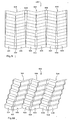
- Structures of this kind are constituted by units which comprise of central tapered strips that are bordered by elongated strips. By pleating these strips according to a special pattern, the structure may collapse down and expand out in a smooth manner.
- a unit 100 comprised of a central tapered strip 110 which is bordered by two elongated strips 130 and 150.
- Tapered strip 110 is pleated along a series of crossing lines 111-121 that cross it widthwise. The fold directions of adjacent crossing lines alternate.
- Elongated strip 130 is pleated along a series of crossing lines 131-141 that cross it widthwise. The fold direction of adjacent crossing lines alternate.
- Crossing line 131 is essentially a continuation of crossing line 111.
- crossing lines 132-141 are essentially continuations of crossing lines 112-121 respectively.
- Elongated strip 150 is pleated along a series of crossing lines 151-161 that cross it widthwise. The fold direction of adjacent crossing lines alternate.
- Crossing line 151 is essentially a continuation of crossing line 111.
- crossing lines 152-161 are essentially continuations of crossing lines 112-121 respectively.
- Central tapered strip 110 is connected to elongated strip 130 along a series of connecting pleat lines 170-181 that are connected end to end. The fold direction of adjacent connecting lines 170-181 alternate. Similarly, central tapered strip 110 is connected to elongated strip 150 along a series of connecting pleat lines 190-201 that are connected end to end. The fold direction of adjacent connecting lines 190-201 alternate.
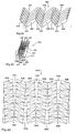
- FIG. 2 unit 100 is shown partially folded.
- Central tapered strip 110 and elongated strips 130 and 150 fold in a zig-zag fashion.
- unit 100 is shown folded to a further degree than Fig. 2.
- Elongated strips 130 and 150 may be seen to fold towards each other.
- Fig. 4 unit 100 is shown to be essentially completely folded.
- Elongated strips 130 and 150 have each folded into a stack.
- the central tapered strip 110 has folded in a zig-zag fashion, such that the planes of the tapered strip lie essentially orthogonal to the planes of the stacked elongated strips 130 and 150.
- Stacked elongated strips 130 and 150 have folded towards each other such that the stacks lie essentially in line with one another.
- a unit 300 which is an alternate embodiment of the invention. It is comprising a central tapered strip 310, which is bordered by two elongated strips 330 and 360. Tapered strip 310 is pleated along a series of crossing lines 311-321 that cross it widthwise. The fold directions of adjacent crossing lines alternate.
- Elongated strip 330 is pleated along a series of crossing lines 331-353 that cross it widthwise. The fold directions of adjacent crossing lines alternate.
- Crossing line 331 is essentially a continuation of crossing line 311.
- crossing lines 332-353 are essentially continuations of crossing lines 311-321.
- Elongated strip 360 is pleated along a series of crossing lines 361-383 that cross it widthwise. The fold directions of adjacent crossing lines alternate.
- Crossing line 361 is essentially a continuation of crossing line 311.
- crossing lines 362-383 are essentially continuations of crossing lines 311-321.
- Central tapered strip 310 is connected to elongated strip 330 along a series of connecting pleat lines 400-411 that are connected end to end. The fold directions of adjacent connecting lines 400-411 alternate. Similarly, central tapered strip 310 is connected to elongated strip 360 along a series of connecting pleat lines 420-431 that are connected end to end. The fold directions of adjacent connecting lines 420-431 alternate.
- unit 300 is shown partially folded.
- Central tapered strip 310 folds in a zig-zag fashion.
- unit 300 is shown folded to a further degree than Fig. 6.
- Elongated strips 330 and 360 may be seen to fold towards each other.
- Fig. 8 unit 300 is shown to be essentially completely folded. Elongated strips 330 and 360 have each folded into a stack.
- the central tapered strip 310 has folded in a zig-zag fashion such that the planes of the central tapered strip lie essentially orthogonal to the planes of the stacked elongated strips 330 and 360.
- stacked elongated strips 330 and 360 have folded towards each other such that the stacks lie essentially in line with one another.
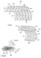
- structure 500 is comprising units 510,520 and 530.
- Unit 510 is comprising central tapered strip 512 and elongated strips 514 and 516.
- unit 520 is comprising central tapered strip 522 and elongated strips 524 and 526
- unit 530 is comprising central tapered strip 532 and elongated strips 534 and 536.
- Unit 510 is connected to adjacent unit 520 by tapered strip 540 which joins elongated strip 516 to elongated strip 524.
- unit 520 is connected to adjacent unit 530 by tapered strip 550 which joins elongated strip 526 to elongated strip 534.
- Figs. 10 and 11 the structure 500 is shown in two partial degrees of folding.
- the elongated strips 514,516,524,526,534 and 536 may be seen to fold towards each other.
- Tapered strips 512,522,532,540 and 550 fold in a zig-zag fashion.
- Fig. 12 the structure 500 is shown completely folded. Elongated strips 514,516,524,526,534 and 536 are folded into stacks which are connected by their adjacent tapered strips.
- the tapered strips 512,522,532,540 and 550 are folded in a zig-zag fashion.
- the planes of the tapered strips lie essentially orthogonal to the planes of the stacked elongated strips.
- the stacks formed by the elongated strips lie essentially in line with one another.
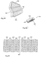
- Fig. 13 is shown a plan view of a structure 600. It is comprising units 610,620 and 630.
- Unit 610 is comprising central tapered strip 612 and elongated strips 614 and 616.
- unit 620 is comprising central tapered strip 622 and elongated strips 624 and 626
- unit 630 is comprising central tapered strip 632 and elongated strips 634 and 636.
- Unit 610 is connected to adjacent unit 620 by tapered strip 640, which joins elongated strip 616 to elongated strip 624.
- unit 620 is connected to adjacent unit 630 by tapered strip 650 which joins elongated strip 626 to elongated strip 634.
- Figs. 14 and 15 the structure 600 is shown in two partial degrees of folding, forming a structure whose shape is a cylindrical section.
- the elongated strips 614,616,624,626,634 and 636 may be seen to fold towards each other.
- Tapered strips 612,622,632,640 and 650 fold in a zig-zag fashion.
- Fig. 16 the structure 600 is shown essentially completely folded. Elongated strips 614,616,624,626,634 and 636 are folded into stacks which are connected by their adjacent tapered strips. The tapered strips 612,622,632,640 and 650 are folded in a zig-zag fashion. The planes of the tapered strips lie essentially orthogonal to the planes of the stacked elongated strips. The stacks formed by the elongated strips lie essentially in line with one another.
- Fig. 17 shows a structure 700 comprises two units 710 and 720, each comprising a central tapered strip and two elongated strips. Units 710 and 720 are connected to each other by a region 730 with an alternate folding pattern.
- the structure 700 is shown in a partially folded condition, forming a tent-shaped structure.
- Fig. 19 shows the structure 700 folded to a further degree than Fig. 18.
- Fig. 20 the structure 700 is shown essentially completely folded.
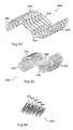
- Fig. 21 shows a structure 800 comprising five units 810,820,830, 840 and 850, each comprising a central tapered strip and two elongated strips. Units 810,820,830,840 and 850 are connected to each other by tapered strips 815,825,835 and 845.
- the structure 800 is shown in a partially folded condition, forming a structure with an S-type curvature.
- Fig. 23 shows the structure 800 folded to a further degree than Fig. 22.
- Fig. 24 the structure 800 is shown essentially completely folded.
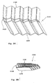
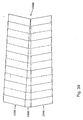
- Fig. 25 shows a structure 900 comprising five units 910,920,930, 940 and 950, each comprising a central tapered strip and two elongated strips. Units 910,920,930,940 and 950 are connected to each other by tapered strips 915,925,935 and 945.
- Fig. 26 the structure 900 is shown in a partially folded condition, forming a conical structure.
- Fig. 27 shows the structure 900 folded to a further degree than Fig. 26.
- Fig. 28 the structure 900 is shown essentially completely folded.
- Fig. 29 shows a structure 1000 having the form of a doubly curved surface. It is comprising three units 1010,1020 and 1030, each comprising a central tapered strip and two elongated strips. Units 1010,1020 and 1030 are connected to each other by tapered strips 1015 and 1025.
- the structure 1000 is shown in a partially folded condition.
- Fig. 31 shows the structure 1000 folded to a further degree than Fig. 30.
- Fig. 32 the structure 1000 is shown essentially completely folded.
- Fig. 33 shows the unit 1100 which illustrates an alternate construction of the invention. It is constituted by a central tapered strip 1120 which is bordered by two elongated strips 1130 and 1140.
- the central strip 1120 is comprising rigid plates which are hingedly attached to each other.
- elongated strips 1130 and 1140 are comprising rigid plates which are hingedly attached to each other.
- Central strip 1120 is hingedly joined to elongated strips 1130 and 1140.
- Fig. 34 shows the unit 1100 in a partially folded state.
- Fig. 35 shows the unit 1100 in its fully collapsed state.
- Fig. 36 shows the unit 1200 which illustrates an alternate construction of the invention. It is constituted by a central tapered strip 1220 which is bordered by two elongated strips 1230 and 1240. In this embodiment of the invention the strips 1220,1230 and 1240 comprise flexible sheets of material where the areas between pleat lines are stiffened by rigid framing members.
- Fig. 37 shows the unit 1200 in a partially folded state.
- Fig. 38 shows the unit 1200 in its fully collapsed state.
- Fig. 39 shows the unit 1300 which is constituted by a central tapered strip 1320 which is bordered by two elongated strips 1330 and 1340.
- the central strip 1320 is tapered in a step-like fashion such that the connecting lines that join the central strip 1320 to the two elongated strips 1330 and 1340 are slightly offset from one another.
Landscapes
- Tents Or Canopies (AREA)
- Blinds (AREA)
Claims (8)
- Einheit (100), (300), (510, 520, 530), (610, 620, 630), (710, 720), (810, 820, 830, 840, 850), (910, 920, 930, 940, 950), (1010, 1020, 1030), (1100), (1200), enthaltend
einen Mittelstreifen (110), (310), (512, 522, 532, 540, 550), (612, 622, 632, 640, 650), (815, 825, 835, 845), (915, 925, 935, 945), (1015, 1025), (1120), (1220), der von zwei langgestreckten Streifen (130, 150), (330, 360), (514, 516, 524, 526, 534, 536), (614, 616, 624, 626, 634, 636), (1130, 1140), (1230, 1240) begrenzt ist,
wobei der Streifen entlang einer Anzahl von Linien (111-121), (311-321), die den Streifen der Breite nach kreuzen, gefaltet ist und die Faltrichtungen dieser benachbarten Kreuzungslinien wechseln,
jeder langgestreckte Streifen entlang einer Anzahl von Schnittlinien (131-141), (151-161), (331-353, 361-383), die den Streifen in der Breite kreuzen, gefaltet ist, die Faltrichtungen dieser benachbarten Schnittlinien wechseln und diese Schnittlinien Fortsetzungen der Linien darstellen, die den Mittelstreifen kreuzen,
der Mittelstreifen mit jedem der beiden langgestreckten Streifen durch eine Anzahl von endweise verbundenen Faltlinien (170-181, 190-201), (400-411, 420-431) verbunden ist und die Faltrichtungen dieser benachbarten Verbindungslinien derartig wechseln,
daß bei gefalteter Einheit jeder der beiden langgestreckten Streifen stapelförmig und der Mittelstreifen zickzackartig gefaltet ist, wobei die beiden gestapelten, langgestreckten Streifen so zueinander hin gefaltet sind, daß die Stapel zueinander in einer Linie liegen, dadurch gekennzeichnet, daß der Mittelstreifen (110), (310), (512, 522, 540, 550), (612, 622, 632, 640, 650), (815, 825, 835, 845), (915, 925, 935, 945), (1015, 1025), (1120), (1220) sich verjüngt und bei zickzackförmig gefaltetem verjüngtem Mittelstreifen die Ebenen des sich verjüngenden Streifens senkrecht zu den Ebenen der übereinander angeordneten, langgestreckten Streifen (130, 150), (330, 360), (514, 516, 524, 526, 534, 536), (614, 616, 624, 626, 634, 636), (1130, 1140), (1230, 1240) liegen. - Umkehrbar entfaltbare Struktur (500), (600), (700), (800), (900), (1000), die wenigstens teilweise Einheiten gemäß Anspruch 1 enthält.
- Einheit (1100) nach Anspruch 1, bei der der mittlere, sich verjüngende Streifen (1120) starre, gelenkig miteinander verbundene Platten enthält, die zwei langgestreckten Streifen (1130, 1140) starre, gelenkig miteinander verbunde Platten enthalten und der Mittelstreifen gelenkig mit den beiden langgestreckten Streifen verbunden ist.
- Umkehrbar entfaltbare Struktur, die wenigstens teilweise Einheiten (1100) gemäß Anspruch 3 enthält.
- Einheit (1200) nach Anspruch 1, bei der der mittlere, sich verjüngende Streifen (1220) eine flexible dünne Platte mit starren Rahmenteilen zur Aussteifung der zwischen Faltlinien liegenden Bereiche enthält und die zwei langgestreckten Streifen (1230, 1240) flexible dünne Platten mit starren Rahmenteilen zur Absteifung der Bereiche zwischen Faltlinien enthalten.
- Umkehrbar entfaltbare Struktur, die wenigstens teilweise aus Einheiten (1200) gemäß Anspruch 5 besteht.
- Einheit (1300), enthaltend
einen Mittelstreifen (1320), an den zwei langgestreckte Streifen (1330, 1340) angrenzen, wobei der Streifen (1320) entlang einer Reihe sich über seine Breite erstreckende Linien gefaltet ist und die Faltrichtungen dieser benachbarten Kreuzungslinien alternieren,
jeder langgestreckte Streifen (1330, 1340) entlang einer Anzahl von Kreuzungslinien, die den Streifen in der Breite schneiden, gefaltet ist, die Faltrichtungen dieser benachbarten Kreuzungslinien wechseln und diese Schnittlinien Fortsetzungen der den Mittelstreifen (1320) kreuzenden Linien darstellen,
der Mittelstreifen (1320) über eine Anzahl von Faltlinien mit jedem der beiden langgestreckten Streifen (1330, 1340) verbunden ist und die Faltrichtungen dieser benachbarten Verbindungslinien derart alternieren,
daß bei zusammengefalteter Einheit (1300) jeder der beiden langgestreckten Streifen (1330, 1340) stapelartig und der Mittelstreifen (1320) zickzackartig gefaltet ist, wobei die beiden übereinander gestapelten, langgestreckten Streifen (1330, 1340) derartig aufeinander zu gefaltet sind, daß die Stapel zueinander in einer Linie liegen, dadurch gekennzeichnet, daß der Mittelstreifen (1320) sich stufenweise derartig verjüngt, daß die den Mittelstreifen (1320) mit den beiden langgestreckten Streifen (1330, 1340) verbindenden Verbindungslinien leicht gegeneinander versetzt sind. - Umkehrbar entfaltbare Struktur, die wenigstens teilweise Einheiten (1300) nach Anspruch 7 enthält.
Applications Claiming Priority (2)
| Application Number | Priority Date | Filing Date | Title |
|---|---|---|---|
| US482369 | 1990-02-20 | ||
| US07/482,369 US4981732A (en) | 1990-02-20 | 1990-02-20 | Reversibly expandable structures |
Publications (2)
| Publication Number | Publication Date |
|---|---|
| EP0443408A1 EP0443408A1 (de) | 1991-08-28 |
| EP0443408B1 true EP0443408B1 (de) | 1994-02-02 |
Family
ID=23915778
Family Applications (1)
| Application Number | Title | Priority Date | Filing Date |
|---|---|---|---|
| EP91101917A Expired - Lifetime EP0443408B1 (de) | 1990-02-20 | 1991-02-12 | Umkehrbare entfaltbare Strukturen |
Country Status (5)
| Country | Link |
|---|---|
| US (1) | US4981732A (de) |
| EP (1) | EP0443408B1 (de) |
| JP (1) | JP3017317B2 (de) |
| CA (1) | CA2035641C (de) |
| DE (1) | DE69101113D1 (de) |
Cited By (4)
| Publication number | Priority date | Publication date | Assignee | Title |
|---|---|---|---|---|
| US7832488B2 (en) | 2005-11-15 | 2010-11-16 | Schlumberger Technology Corporation | Anchoring system and method |
| US7896088B2 (en) | 2007-12-21 | 2011-03-01 | Schlumberger Technology Corporation | Wellsite systems utilizing deployable structure |
| US8291781B2 (en) | 2007-12-21 | 2012-10-23 | Schlumberger Technology Corporation | System and methods for actuating reversibly expandable structures |
| US8733453B2 (en) | 2007-12-21 | 2014-05-27 | Schlumberger Technology Corporation | Expandable structure for deployment in a well |
Families Citing this family (36)
| Publication number | Priority date | Publication date | Assignee | Title |
|---|---|---|---|---|
| US5234727A (en) * | 1991-07-19 | 1993-08-10 | Charles Hoberman | Curved pleated sheet structures |
| BR9706202C1 (pt) * | 1997-10-20 | 2002-03-26 | Reginaldo Guedes Marinho | Elemento de construção autoportante |
| US6190231B1 (en) | 1998-12-04 | 2001-02-20 | Charles Hoberman | Continuously rotating mechanisms |
| USD444416S1 (en) | 2000-04-27 | 2001-07-03 | Hallmark Cards, Incorporated | Decorative bow |
| US6237819B1 (en) | 2000-04-27 | 2001-05-29 | Hallmark Cards Incorporated | Decorative bow |
| WO2002063111A1 (en) * | 2001-02-07 | 2002-08-15 | Charles Hoberman | Loop assemblies having a central link |
| US6748712B2 (en) | 2002-06-14 | 2004-06-15 | Usg Interiors, Inc. | Scalable suspension system for dome shaped ceilings |
| US20050100707A1 (en) * | 2003-08-06 | 2005-05-12 | John Houston | Folding and rotating toroidal structure |
| US7125015B2 (en) * | 2003-10-17 | 2006-10-24 | Charles Hoberman | Transforming puzzle |
| US7540215B2 (en) * | 2003-10-20 | 2009-06-02 | Charles Hoberman | Synchronized ring linkages |
| US7644721B2 (en) * | 2005-01-14 | 2010-01-12 | Charles Hoberman | Synchronized four-bar linkages |
| US20070007289A1 (en) * | 2005-07-08 | 2007-01-11 | Charles Hoberman | Collapsible containers |
| US7794019B2 (en) * | 2005-07-08 | 2010-09-14 | Charles Hoberman | Folding structures made of thick hinged sheets |
| DE102006003317B4 (de) | 2006-01-23 | 2008-10-02 | Alstom Technology Ltd. | Rohrbündel-Wärmetauscher |
| WO2007087574A2 (en) * | 2006-01-25 | 2007-08-02 | Strategix, Llc | Collapsible shelter |
| US7584777B2 (en) * | 2006-04-05 | 2009-09-08 | Charles Hoberman | Panel assemblies for variable shading and ventilation |
| US7559174B2 (en) * | 2006-05-19 | 2009-07-14 | Charles Hoberman | Covering structure having links and stepped overlapping panels both of which are pivotable between extended position and a retracted position in which the panels are stacked |
| US7762938B2 (en) * | 2006-07-24 | 2010-07-27 | Tessellated Group, Llc | Three-dimensional support structure |
| US20080073945A1 (en) * | 2006-08-09 | 2008-03-27 | Charles Hoberman | Folding structures made of thick hinged sheets |
| USD620351S1 (en) * | 2009-02-26 | 2010-07-27 | Sri Sports Ltd. | Packing box |
| US8615970B2 (en) | 2009-03-24 | 2013-12-31 | Charles Hoberman | Panel assemblies having controllable surface properties |
| US9557119B2 (en) | 2009-05-08 | 2017-01-31 | Arvos Inc. | Heat transfer sheet for rotary regenerative heat exchanger |
| US8622115B2 (en) | 2009-08-19 | 2014-01-07 | Alstom Technology Ltd | Heat transfer element for a rotary regenerative heat exchanger |
| US9200853B2 (en) | 2012-08-23 | 2015-12-01 | Arvos Technology Limited | Heat transfer assembly for rotary regenerative preheater |
| CN103015531B (zh) * | 2012-12-05 | 2014-10-22 | 天津大学 | 具有一个刚性自由度的可折叠管状结构 |
| US9742348B2 (en) | 2013-09-16 | 2017-08-22 | Brigham Young University | Foldable array of three-dimensional panels including functional electrical components |
| US9512618B2 (en) * | 2013-11-20 | 2016-12-06 | Brigham Young University | Rigidly foldable array of three-dimensional bodies |
| US10175006B2 (en) | 2013-11-25 | 2019-01-08 | Arvos Ljungstrom Llc | Heat transfer elements for a closed channel rotary regenerative air preheater |
| US9857026B1 (en) | 2014-07-11 | 2018-01-02 | Charles Hoberman | Construction method for foldable units |
| US10094626B2 (en) | 2015-10-07 | 2018-10-09 | Arvos Ljungstrom Llc | Alternating notch configuration for spacing heat transfer sheets |
| US11078698B2 (en) | 2016-02-01 | 2021-08-03 | Brigham Young University | Non-planar closed-loop hinge mechanism with rolling-contact hinge |
| US10465376B1 (en) | 2016-06-28 | 2019-11-05 | Charles Hoberman | Construction method for foldable polyhedral enclosures |
| USD828446S1 (en) * | 2017-04-04 | 2018-09-11 | Min Yang Kim | Book stand |
| WO2020028797A1 (en) | 2018-08-03 | 2020-02-06 | trac9, LLC | Collapsible structure |
| JP7338718B2 (ja) * | 2022-01-28 | 2023-09-05 | 積水ハウス株式会社 | 基礎ベース型枠および基礎ベース型枠の製造方法 |
| US12473670B2 (en) | 2023-05-16 | 2025-11-18 | The Hong Kong University Of Science And Technology | Woven quadrilateral mesh origami structures and related functional materials |
Family Cites Families (13)
| Publication number | Priority date | Publication date | Assignee | Title |
|---|---|---|---|---|
| US1802101A (en) * | 1924-11-04 | 1931-04-21 | Western Electric Co | Molded article |
| US1997022A (en) * | 1933-04-27 | 1935-04-09 | Ralph M Stalker | Advertising medium or toy |
| US1944696A (en) * | 1933-10-17 | 1934-01-23 | Reichl Ernst | Folding panel device |
| US2164966A (en) * | 1937-09-09 | 1939-07-04 | Tutein Kamma | Pleated material and method of making the same |
| US2922239A (en) * | 1956-05-04 | 1960-01-26 | Jr Clifford H Glynn | Decorative ornament |
| US3186524A (en) * | 1961-04-11 | 1965-06-01 | Jr Otto Lucien Spaeth | Panelized building construction |
| US3302321A (en) * | 1963-08-16 | 1967-02-07 | Wallace G Walker | Foldable structure |
| NL7409627A (nl) * | 1973-10-01 | 1975-04-03 | Cartonneries De La Lys Lys Sa | Opvouwbare verpakking en inrichting voor het stellen en opvouwen daarvan. |
| US4142321A (en) * | 1976-10-18 | 1979-03-06 | Coppa Anthony P | Three-dimensional folded chain structures |
| US4140317A (en) * | 1977-05-11 | 1979-02-20 | Ramney Tiberius J | Containerized greeting card and game toy |
| US4354842A (en) * | 1981-05-28 | 1982-10-19 | Baldwin, Stoddard & Co. | System for utilizing interactive blocks to teach arithmetic |
| US4492723A (en) * | 1982-10-14 | 1985-01-08 | Chadwick Ii Lee S | Curvilinear polyhedral construction kit |
| US4780344A (en) * | 1986-09-02 | 1988-10-25 | Hoberman Charles S | Reversibly expandable three-dimensional structure |
-
1990
- 1990-02-20 US US07/482,369 patent/US4981732A/en not_active Expired - Lifetime
-
1991
- 1991-02-04 CA CA002035641A patent/CA2035641C/en not_active Expired - Fee Related
- 1991-02-12 DE DE91101917T patent/DE69101113D1/de not_active Expired - Lifetime
- 1991-02-12 EP EP91101917A patent/EP0443408B1/de not_active Expired - Lifetime
- 1991-02-20 JP JP3109912A patent/JP3017317B2/ja not_active Expired - Fee Related
Cited By (5)
| Publication number | Priority date | Publication date | Assignee | Title |
|---|---|---|---|---|
| US7832488B2 (en) | 2005-11-15 | 2010-11-16 | Schlumberger Technology Corporation | Anchoring system and method |
| US7896088B2 (en) | 2007-12-21 | 2011-03-01 | Schlumberger Technology Corporation | Wellsite systems utilizing deployable structure |
| US8291781B2 (en) | 2007-12-21 | 2012-10-23 | Schlumberger Technology Corporation | System and methods for actuating reversibly expandable structures |
| US8733453B2 (en) | 2007-12-21 | 2014-05-27 | Schlumberger Technology Corporation | Expandable structure for deployment in a well |
| US9169634B2 (en) | 2007-12-21 | 2015-10-27 | Schlumberger Technology Corporation | System and methods for actuating reversibly expandable structures |
Also Published As
| Publication number | Publication date |
|---|---|
| US4981732A (en) | 1991-01-01 |
| EP0443408A1 (de) | 1991-08-28 |
| CA2035641A1 (en) | 1991-08-21 |
| CA2035641C (en) | 2001-08-07 |
| JP3017317B2 (ja) | 2000-03-06 |
| JPH05106370A (ja) | 1993-04-27 |
| DE69101113D1 (de) | 1994-03-17 |
Similar Documents
| Publication | Publication Date | Title |
|---|---|---|
| EP0443408B1 (de) | Umkehrbare entfaltbare Strukturen | |
| US5234727A (en) | Curved pleated sheet structures | |
| US6052966A (en) | Retractable cover having a panel made from cell-inside-a-cell honeycomb material | |
| US4865889A (en) | Void filler and method for manufacture | |
| US4780344A (en) | Reversibly expandable three-dimensional structure | |
| EP1203127B1 (de) | Deckensystem mit austauschbaren platten | |
| US6257412B1 (en) | Folded cushioning material for packaging | |
| US20120291364A1 (en) | Portable shelter structure and manufacturing process | |
| AU701482B2 (en) | Cellular structure | |
| WO2007087574A2 (en) | Collapsible shelter | |
| AU611346B1 (en) | Expandable and collapsible cellular shade | |
| WO2007018900A2 (en) | Folding structures made of thick-hinged sheets | |
| US4333622A (en) | Knockdown spacer for bookshelves and the like | |
| US20120114900A1 (en) | System and method for forming a support article | |
| US20050089675A1 (en) | Partially collapsible structure | |
| US5839762A (en) | Structure of book page | |
| CA2344617C (en) | Enclosed retractable panel made from cell-inside-a-cell honeycomb material | |
| JPH0251511B2 (de) | ||
| JP3728704B2 (ja) | 二重構造プリーツ形状スクリーン装置、二重構造プリーツ形状スクリーン及び二重構造プリーツ形状スクリーン装置の製造方法 | |
| CA2316940A1 (en) | Carton construction | |
| JP7216236B1 (ja) | 折り構造体、剛体折り構造体および折り構造体の製造方法 | |
| GB2375777A (en) | Folding hollow constructional element for receipt of filler material | |
| EP1439127B1 (de) | Flachlegbarer Behälter aus faltbarem Material | |
| KR102702943B1 (ko) | 유아용 매트 | |
| EP1065959B1 (de) | Anordnung mit in gegenüberliegenden richtungen offenen zellen und gebrauch einer solchen anordnung |
Legal Events
| Date | Code | Title | Description |
|---|---|---|---|
| PUAI | Public reference made under article 153(3) epc to a published international application that has entered the european phase |
Free format text: ORIGINAL CODE: 0009012 |
|
| AK | Designated contracting states |
Kind code of ref document: A1 Designated state(s): DE ES FR GB IT |
|
| 17P | Request for examination filed |
Effective date: 19920203 |
|
| 17Q | First examination report despatched |
Effective date: 19920615 |
|
| GRAA | (expected) grant |
Free format text: ORIGINAL CODE: 0009210 |
|
| AK | Designated contracting states |
Kind code of ref document: B1 Designated state(s): DE ES FR GB IT |
|
| PG25 | Lapsed in a contracting state [announced via postgrant information from national office to epo] |
Ref country code: IT Free format text: LAPSE BECAUSE OF FAILURE TO SUBMIT A TRANSLATION OF THE DESCRIPTION OR TO PAY THE FEE WITHIN THE PRE;WARNING: LAPSES OF ITALIAN PATENTS WITH EFFECTIVE DATE BEFORE 2007 MAY HAVE OCCURRED AT ANY TIME BEFORE 2007. THE CORRECT EFFECTIVE DATE MAY BE DIFFERENT FROM THE ONE RECORDED.SCRIBED TIME-LIMIT Effective date: 19940202 Ref country code: ES Free format text: THE PATENT HAS BEEN ANNULLED BY A DECISION OF A NATIONAL AUTHORITY Effective date: 19940202 Ref country code: DE Effective date: 19940202 Ref country code: FR Effective date: 19940202 |
|
| REF | Corresponds to: |
Ref document number: 69101113 Country of ref document: DE Date of ref document: 19940317 |
|
| EN | Fr: translation not filed | ||
| PLBE | No opposition filed within time limit |
Free format text: ORIGINAL CODE: 0009261 |
|
| STAA | Information on the status of an ep patent application or granted ep patent |
Free format text: STATUS: NO OPPOSITION FILED WITHIN TIME LIMIT |
|
| 26N | No opposition filed | ||
| PG25 | Lapsed in a contracting state [announced via postgrant information from national office to epo] |
Ref country code: GB Effective date: 19950212 |
|
| GBPC | Gb: european patent ceased through non-payment of renewal fee |
Effective date: 19950212 |