EP0443085B1 - Electric overhead conductor with integrated light wave guides - Google Patents
Electric overhead conductor with integrated light wave guides Download PDFInfo
- Publication number
- EP0443085B1 EP0443085B1 EP90117624A EP90117624A EP0443085B1 EP 0443085 B1 EP0443085 B1 EP 0443085B1 EP 90117624 A EP90117624 A EP 90117624A EP 90117624 A EP90117624 A EP 90117624A EP 0443085 B1 EP0443085 B1 EP 0443085B1
- Authority
- EP
- European Patent Office
- Prior art keywords
- wires
- lwg
- layer
- tube
- tubes
- Prior art date
- Legal status (The legal status is an assumption and is not a legal conclusion. Google has not performed a legal analysis and makes no representation as to the accuracy of the status listed.)
- Revoked
Links
Images
Classifications
-
- G—PHYSICS
- G02—OPTICS
- G02B—OPTICAL ELEMENTS, SYSTEMS OR APPARATUS
- G02B6/00—Light guides; Structural details of arrangements comprising light guides and other optical elements, e.g. couplings
- G02B6/44—Mechanical structures for providing tensile strength and external protection for fibres, e.g. optical transmission cables
- G02B6/4401—Optical cables
- G02B6/4415—Cables for special applications
- G02B6/4416—Heterogeneous cables
- G02B6/4422—Heterogeneous cables of the overhead type
- G02B6/4423—Electro-corrosion preventing means
-
- G—PHYSICS
- G02—OPTICS
- G02B—OPTICAL ELEMENTS, SYSTEMS OR APPARATUS
- G02B6/00—Light guides; Structural details of arrangements comprising light guides and other optical elements, e.g. couplings
- G02B6/44—Mechanical structures for providing tensile strength and external protection for fibres, e.g. optical transmission cables
- G02B6/4401—Optical cables
- G02B6/4415—Cables for special applications
- G02B6/4416—Heterogeneous cables
- G02B6/4422—Heterogeneous cables of the overhead type
-
- H—ELECTRICITY
- H01—ELECTRIC ELEMENTS
- H01B—CABLES; CONDUCTORS; INSULATORS; SELECTION OF MATERIALS FOR THEIR CONDUCTIVE, INSULATING OR DIELECTRIC PROPERTIES
- H01B5/00—Non-insulated conductors or conductive bodies characterised by their form
- H01B5/08—Several wires or the like stranded in the form of a rope
- H01B5/10—Several wires or the like stranded in the form of a rope stranded around a space, insulating material, or dissimilar conducting material
- H01B5/108—Several wires or the like stranded in the form of a rope stranded around a space, insulating material, or dissimilar conducting material stranded around communication or control conductors
Definitions
- the invention relates to an electrical overhead line with integrated optical fibers (hereinafter referred to as 'LWL').
- Such an optical fiber overhead cable is described in EP 0 286 804 A2. It has wires of the same diameter, wires made of steel in the core and the first stranding layer and wires made of aluminum or an aluminum alloy in the following layers.
- the tube for the fiber optic cable (hereinafter referred to as the 'fiber optic tube') is made of stainless steel or fiber-reinforced plastic, and it is arranged instead of a wire in a wire layer located below the uppermost layer, in the exemplary embodiment shown instead of a steel wire in the first layer.
- the fiber optic cables are loosely inserted in the fiber optic tube, which is specified with selected dimensions for the outer diameter and wall thickness. It is also proposed to choose the outside diameter to be equal to or about 5% smaller than the diameter of the replaced wire.
- the core and the first layer are made of round wires made of (mainly) tensile material (e.g. steel), the second layer is made of round or profile wires made of (mainly) electrically conductive material (e.g. aluminum).
- the fiber optic tube consists of a sleeve made of metal (especially stainless steel), which is surrounded by a reinforcement made of profiled wire or metal strips.
- the invention is based on the object, starting from a fiber optic overhead cable of the type specified, to provide further advantageous rope constructions, in particular to increase the number of optical communication lines (fiber optic) and the protection of the fiber optic tube in the rope.
- efforts are being made to make a metallic fiber optic tube usable for independent electricity transport.
- the solution has the advantage of arranging the fiber optic tubes in the rope as insensitive to tension and pressure as possible.
- the (mainly) tensile wires are made of steel or of steel with an aluminum jacket (Stalum) and the (mainly) electrically conductive wires are made of aluminum or an Al alloy.
- the fiber optic tube is preferably made of stainless steel and has the same or a 5% smaller outer diameter than the wire it replaces.
- LWL optical communication lines
- the protection of the fiber optic tube in the rope is increased if the metal tube is surrounded on the outside by a sheath that protects against abrasion and / or corrosion and is designed differently depending on the purpose and use.
- the metal tube contains one or more optical fibers on the inside, the lots of each optical fiber in the tube corresponding to an expansion reserve of the optical fiber of 4 to 15%, and the tube, as is known, filled with a gel.
- the protective cover of the fiber optic tube it should be explained that dynamic tests on overhead cables are known to cause slight fretting of the individual wires over time. The usual greasing of the wires hardly changes this. The same applies to a fiber optic tube instead of a wire. Abrasion protection is achieved if the metal fiber optic tube receives a thin, in relation to the tube wall thickness, jacket made of an abrasion-resistant plastic, for. B. from a polyamide (nylon), such as is used for axle bearings. In practice, the outer diameter of the metal tube is reduced to such an extent (by twice the wall thickness of the protective cover) that the coated fiber optic tube adapts to the relevant rope structure in the usual way.
- the metal fiber optic tube can be provided with a jacket made of a water-impermeable, electrically insulating polyamide or with an aluminum coating or with a galvanic coating made of zinc.
- a protective cover made of such a polyamide enables the use of slightly corrosive metals for the FO tube, on the other hand, it prevents corrosion of the steel wires if the tube is made of copper and in the immediate vicinity of steel wires lies.
- a protective cover made of abrasion-resistant plastic opens up the advantageous possibility of using the metal tube for the transport of electricity, as is required, for example, over very long distances to supply repeaters for the regeneration of the optical signals.
- the expansion reserve is determined and optimized for the individual case using various calculation formulas.
- the most important of the aforementioned influencing factors include c) and d).
- the expansion reserve has a value of 4 to 15% o. H.
- the fiber optic cables inserted in the stainless steel tube are longer by this value than the straight tube when it is not under tension or pressure. - For optimization, it is advantageous if the fiber optic tube or tubes are arranged in the first steel wire layer of the rope.
Abstract
Description
Die Erfindung betrifft ein elektrisches Freileiterseil mit integrierten Lichtwellenleitern (im folgenden mit 'LWL' bezeichnet).The invention relates to an electrical overhead line with integrated optical fibers (hereinafter referred to as 'LWL').
Ein derartiges LWL-Freileiterseil ist in EP 0 286 804 A2 beschrieben. Es hat durchmessergleiche Drähte, im Kern und der ersten Verseillage Drähte aus Stahl und in den folgenden Lagen Drähte aus Aluminium oder einer Aluminiumlegierung. Das Röhrchen für die LWL (im folgenden 'LWL-Röhrchen' genannt) ist aus Edelstahl oder faserverstärktem Kunststoff, und es ist anstelle eines Drahtes in einer unterhalb der obersten Lage befindlichen Drahtlage angeordnet, in dem dargestellten Ausführungsbeispiel anstelle eines Stahldrahtes in der ersten Lage. Die LWL sind lose in das LWL-Röhrchen eingelegt, welches mit ausgewählten Dimensionen für Außendurchmesser und Wanddicke angegeben ist. Es wird auch vorgeschlagen, den Außendurchmesser gleich oder um etwa 5 % kleiner zu wählen, als der Durchmesser des ersetzten Drahts.Such an optical fiber overhead cable is described in EP 0 286 804 A2. It has wires of the same diameter, wires made of steel in the core and the first stranding layer and wires made of aluminum or an aluminum alloy in the following layers. The tube for the fiber optic cable (hereinafter referred to as the 'fiber optic tube') is made of stainless steel or fiber-reinforced plastic, and it is arranged instead of a wire in a wire layer located below the uppermost layer, in the exemplary embodiment shown instead of a steel wire in the first layer. The fiber optic cables are loosely inserted in the fiber optic tube, which is specified with selected dimensions for the outer diameter and wall thickness. It is also proposed to choose the outside diameter to be equal to or about 5% smaller than the diameter of the replaced wire.
Ein ähnliches Freileiterseil mit LWL-Röhrchen in einer Stahldrahtlage ist in der DE 37 42 925 beschrieben. Dort werden als Material für das LWL-Röhrchen nur bestimmte Kunststoffe ausgewählt.A similar overhead cable with fiber optic tubes in a steel wire layer is described in DE 37 42 925. There, only certain plastics are selected as the material for the fiber optic tube.
Ein weiteres LWL-Freileiterseil ist in DE 38 20 730 A1 (Freileiter mit einer optischen Nachrichtenleitung) beschrieben. Hier sind Seilausführungen angegeben, bei denen die Drähte des Kerns und der einzelnen Verseillagen verschiedene Durchmesser haben. Kern und erste Lage sind aus Runddrähten aus (hauptsächlich) zugfestem Material (etwa Stahl), die zweite Lage ist aus Rund- oder Profildrähten aus (hauptsächlich) elektrisch leitfähigem Material (etwa Aluminium). Hier besteht das LWL-Röhrchen aus einer Hülle aus Metall (insbesonders aus Edelstahl), die von einer Verstärkung aus Profildraht oder Metallstreifen umgeben ist.Another fiber optic overhead line cable is described in DE 38 20 730 A1 (overhead line with an optical communication line). Rope versions are specified here in which the wires of the core and the individual strand layers have different diameters. The core and the first layer are made of round wires made of (mainly) tensile material (e.g. steel), the second layer is made of round or profile wires made of (mainly) electrically conductive material (e.g. aluminum). Here, the fiber optic tube consists of a sleeve made of metal (especially stainless steel), which is surrounded by a reinforcement made of profiled wire or metal strips.
Der Erfindung liegt die Aufgabe zugrunde, ausgehend von einem LWL-Freileiterseil der eingangs angegebenen Art weitere vorteilhafte Seilkonstruktionen anzugeben, insbesondere die Zahl der optischen Nachrichtenleitungen (LWL) und den Schutz des LWL-Röhrchens im Seil zu erhöhen. Außerdem wird angestrebt, ein metallisches LWL-Röhrchen für den unabhängigen stromtransport einsetzbar zu machen.The invention is based on the object, starting from a fiber optic overhead cable of the type specified, to provide further advantageous rope constructions, in particular to increase the number of optical communication lines (fiber optic) and the protection of the fiber optic tube in the rope. In addition, efforts are being made to make a metallic fiber optic tube usable for independent electricity transport.
Die Lösung dieser Aufgabe ist in den Merkmalen des Anspruchs 1 angegeben.The solution to this problem is specified in the features of
Die Lösung bringt den Vorteil einer möglichst zug- und druck-unempfindlichen Anordnung der LWL-Röhrchen im Seil.The solution has the advantage of arranging the fiber optic tubes in the rope as insensitive to tension and pressure as possible.
Wie bekannt, sind die (hauptsächlich) zugfesten Drähte aus Stahl oder aus Stahl mit Aluminium-Ummantelung (Stalum) und die (hauptsächlich) elektrisch leitenden Drähte aus Aluminium oder einer Al-Legierung. Das LWL-Röhrchen ist vorzugsweise aus Edelstahl und hat gegenüber dem von ihm ersetzten Draht den gleichen oder einen um etwa 5 % kleineren Außendurchmesser.As is known, the (mainly) tensile wires are made of steel or of steel with an aluminum jacket (Stalum) and the (mainly) electrically conductive wires are made of aluminum or an Al alloy. The fiber optic tube is preferably made of stainless steel and has the same or a 5% smaller outer diameter than the wire it replaces.
Der weitere Vorteil einer Erhöhung der Zahl der optischen Nachrichtenleitungen (LWL) wird erreicht, wenn mehrere der zugfesten Drähte des Seils in symmetrischer Anordnung durch je ein LWL-Röhrchen ersetzt werden. Vorzugsweise geschieht dies in der ersten Drahtlage bei zwei einander diametral gegenüberliegenden Drähten.The further advantage of an increase in the number of optical communication lines (LWL) is achieved if several of the tensile wires of the rope are replaced in a symmetrical arrangement by one LWL tube each. This is preferably done in the first wire layer with two diametrically opposite wires.
Der Schutz des LWL-Röhrchens im Seil wird erhöht, wenn das metallene Röhrchen außen von einer gegen Abrieb oder/und Korrosion schützenden Hülle umgeben wird, die je nach Zweck und Verwendung verschieden ausgebildet ist.The protection of the fiber optic tube in the rope is increased if the metal tube is surrounded on the outside by a sheath that protects against abrasion and / or corrosion and is designed differently depending on the purpose and use.
Und schließlich ist es vorteilhaft, wenn das metallene Röhrchen innen einen oder mehrere LWL enthält, wobei die Lose eines jeden LWL im Röhrchen einer Dehnungsreserve des LWL von 4 bis 15 ‰ entspricht, und das Rörchen wie bekannt mit einem Gel gefüllt ist.Finally, it is advantageous if the metal tube contains one or more optical fibers on the inside, the lots of each optical fiber in the tube corresponding to an expansion reserve of the optical fiber of 4 to 15%, and the tube, as is known, filled with a gel.
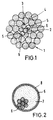
Ein Ausführungsbeispiel der Erfindung ist in der Zeichnung dargestellt und wird im folgenden näher beschrieben. Es zeigen im Querschnitt
- Fig. 1 ein dreilagiges LWL-Freileiterseil mit ungleichem Drahtdurchmesser, bei dem in der ersten Lage Stahldrähte zwei einander diametral gegenüberliegende LWL-Röhrchen angeordnet sind, und
- Fig. 2 daraus vergrößert das LWL-Röhrchen.
- Fig. 1 is a three-layer fiber optic overhead cable with an uneven wire diameter, in which in the first layer steel wires two diametrically opposed fiber optic tubes are arranged, and
- Fig. 2 enlarges the fiber optic tube.
Bezeichnet sind mit
- 1 Drähte des Seils (LWL-Erdseil 22,4 mm ⌀)
- 2 Kerndraht aus Stahl (2,49 mm ⌀)
- 3 Erste Drahtlage (Verseillage) aus 4 Stahldrähten und 2 LWL-Röhrchen (2,49 mm ⌀)
- 4 Zweite Drahtlage aus 9 Aluminiumdrähten, darüber dritte Lage aus 15 ebensolchen Drähten (3,74 mm ⌀)
- 5 LWL-Röhrchen aus Edelstahl
- 6 LWL, Bündel aus 7 optischen Fasern 9/125
- 7 Gel, Röhrchenausfüllung,
- 8 Schutzhülle um das LWL-Röhrchen.
- 1 wire of the rope (fiber optic earth rope 22.4 mm ⌀)
- 2 steel core wires (2.49 mm ⌀)
- 3 First wire layer (stranded layer) made of 4 steel wires and 2 fiber optic tubes (2.49 mm ⌀)
- 4 Second wire layer made of 9 aluminum wires, above that third layer made of 15 same wires (3.74 mm ⌀)
- 5 fiber optic tubes made of stainless steel
- 6 FO, bundle of 7 optical fibers 9/125
- 7 gel, tube filling,
- 8 protective cover around the fiber optic tube.
Der Aufbau des Seils ist aus den beiden Figuren ohne weitere Erläuterung verständlich.The structure of the rope can be understood from the two figures without further explanation.
Zur Schutzhülle des LWL-Röhrchens sei erläutert: Von dynamischen Untersuchungen an Freileiterseilen ist bekannt, daß im Lauf der Zeit ein leichter Abrieb (Fretting) der Einzeldrähte stattfindet. Hieran ändert auch die übliche Fettung der Drähte kaum etwas. Entsprechendes gilt für ein anstelle eines Drahtes angeordnetes LWL-Röhrchen. Ein Abriebschutz wird erreicht, wenn das metallene LWL-Röhrchen einen, im Verhältnis zur Röhrchen-Wandstärke dünnen, Mantel aus einem abriebfesten Kunststoff erhält, z. B. aus einem Polyamid (Nylon), wie es für Achslager verwendet wird. In der Praxis wird der Außendurchmesser des Metallröhrchens so weit reduziert (um die doppelte Wandstärke der Schutzhülle), daß sich das umhüllte LWL-Röhrchen dem betreffenden Seilaufbau in der üblichen Weise anpaßt.Regarding the protective cover of the fiber optic tube, it should be explained that dynamic tests on overhead cables are known to cause slight fretting of the individual wires over time. The usual greasing of the wires hardly changes this. The same applies to a fiber optic tube instead of a wire. Abrasion protection is achieved if the metal fiber optic tube receives a thin, in relation to the tube wall thickness, jacket made of an abrasion-resistant plastic, for. B. from a polyamide (nylon), such as is used for axle bearings. In practice, the outer diameter of the metal tube is reduced to such an extent (by twice the wall thickness of the protective cover) that the coated fiber optic tube adapts to the relevant rope structure in the usual way.
Zum Korrosionsschutz kann das metallene LWL-Röhrchen mit einem Mantel aus einem wasserundurchlässigen, elektrisch isolierenden Polyamid oder mit einer Auflage aus Aluminium oder mit einem galvanischen überzug aus Zink versehen werden. Einerseits ermöglicht eine Schutzhülle aus einem solchen Polyamid, für das LWL-Röhrchen auch leicht korrodierende Metalle einzusetzen, anderseits verhindert sie eine Korrosion der Stahldrähte, falls das Röhrchen aus Kupfer besteht und in der unmittelbaren Nähe von Stahldrähten liegt. Zudem eröffnet eine Schutzhülle aus abriebfestem Kunststoff die vorteilhafte Möglichkeit, das Metallröhrchen für den Stromtransport zu benutzen, wie er etwa auf sehr langen Strecken zur Speisung von Repeatern für die Regenerierung der optischen Signale erforderlich ist.For corrosion protection, the metal fiber optic tube can be provided with a jacket made of a water-impermeable, electrically insulating polyamide or with an aluminum coating or with a galvanic coating made of zinc. On the one hand, a protective cover made of such a polyamide enables the use of slightly corrosive metals for the FO tube, on the other hand, it prevents corrosion of the steel wires if the tube is made of copper and in the immediate vicinity of steel wires lies. In addition, a protective cover made of abrasion-resistant plastic opens up the advantageous possibility of using the metal tube for the transport of electricity, as is required, for example, over very long distances to supply repeaters for the regeneration of the optical signals.
Zur Dehnungsreserve der LWL im Edelstahlröhrchen (LWL-Röhrchen) sei angemerkt: Sie hängt ab
- a) von den Aufbaudaten des Freileiterseils,
- b) von der Schlaglänge der Stahldrahtlage, in der das LWL-Röhrchen mitverseilt ist,
- c) von der Schlaglänge des LWL-Bündels innerhalb des LWL-Röhrchens,
- d) vom Mastabstand,
- e) vom eingestellten Seilzug beim Aufhängen des Seils bei gegebener Temperatur,
- f) von der Höhe der maximal zu erwartenden Eislast und/oder Windlast,
- g) von der bleibenden Dehnung des Seils pro Lebensdauer,
- h) vom Durchhang des Seils und
- i) von den technischen Toleranzen der verschiedenen Fertigungsstufen des LWL-Röhrchens und des Freileiterseils.
- a) the construction data of the overhead cable,
- b) the lay length of the steel wire layer in which the fiber optic tube is also stranded,
- c) the length of lay of the fiber optic bundle within the fiber optic tube,
- d) the mast spacing,
- e) the set cable pull when hanging the cable at a given temperature,
- f) the height of the maximum expected ice load and / or wind load,
- g) the permanent elongation of the rope per lifetime,
- h) the sag of the rope and
- i) from the technical tolerances of the different production stages of the fiber optic tube and the overhead line.
Die Dehnungsreserve wird mittels verschiedener Berechnungsformeln für den Einzelfall ermittelt und optimiert. Zu den wichtigsten der vorerwähnten Einflußgrößen gehören c) und d). In den meisten Fällen hat die Dehnungsreserve einen Wert von 4 bis 15 %o, d. h. die im Edelstahlröhrchen eingebrachten LWL sind um diesen Wert länger als das gerade gestreckte Röhrchen im zug- und druckunbelasteten Zustand. - Für die Optimierung ist es vorteilhaft, wenn das oder die LWL-Röhrchen in der ersten Stahldrahtlage des Seils angeordnet sind.The expansion reserve is determined and optimized for the individual case using various calculation formulas. The most important of the aforementioned influencing factors include c) and d). In most cases, the expansion reserve has a value of 4 to 15% o. H. The fiber optic cables inserted in the stainless steel tube are longer by this value than the straight tube when it is not under tension or pressure. - For optimization, it is advantageous if the fiber optic tube or tubes are arranged in the first steel wire layer of the rope.
Claims (7)
- An electric overhead conductor with integrated light wave guides (6), comprising- a core wire (2) made of steel wire or aluminium-coated steel wire,- surrounded by at least one layer (3) comprising wires of steel or aluminium-coated steel and chiefly responsible for the tensile strength of the conductor,- surrounded by at least one layer (4) comprising wires of aluminium or an aluminium alloy and chiefly responsible for the current conduction of the conductor,- wherein the wires within a layer of wires have the same diameter,- wherein at least two metal tubes (5), hereinafter referred to as "LWG tubes", are symmetrically arranged, in place of a respective wire, in a layer (3) comprising steel wires or aluminium-coated steel wires and chiefly responsible for the tensile strength of the conductor,- wherein one or more light wave guides (6) are loosely arranged in the LWG tubes (5),- wherein each LWG tube (5) has the same outer diameter or an outer diameter smaller by approximately 5% in relation to the wire it replaces,- and each LWG tube (5) is surrounded by a protective covering (8) of abrasion-resistant plastics.
- An overhead conductor according to claim 1, characterised in that the protective covering (8) of the LWG tubes (5) is made of electrically insulating polyamide impermeable to water.
- An overhead conductor according to one of the preceding claims, characterised in that two LWG tubes (5) in a layer of wires (3) are diametrically opposed.
- An overhead conductor according to one of the preceding claims, characterised in that all the wires (1) of the overhead conductor have the same diameter.
- An overhead conductor according to one of the preceding claims, characterised in that the LWG tubes (5) are either all made of high-grade steel or all made of copper.
- An overhead conductor according to one of the preceding claims, characterised in that the first layer of wires (3) over the core wire comprises four wires and two diametrically opposed LWG tubes (5), in that the second layer of wires (4) comprises nine wires and the outer layer of wires comprises fifteen wires and in that the wires of the second and the outer layer are made of aluminium or an aluminium alloy and in that the diameters of all the wires and the LWG tubes range from 2.0 to 4.0 mm.
- An overhead conductor according to one of the preceding claims, characterised in that the amount of play of any light wave guide in the LWG tube (5) corresponds to an expansion reserve of 4 to 15 per mil, related to the LWG tube at 20°C in the straightened state without tensile stress, and in that the LWG tube is filled with a gel (7).
Applications Claiming Priority (2)
| Application Number | Priority Date | Filing Date | Title |
|---|---|---|---|
| DE4005080 | 1990-02-17 | ||
| DE4005080A DE4005080A1 (en) | 1990-02-17 | 1990-02-17 | ELECTRIC WIRING CABLE WITH INTEGRATED LIGHT-WAVE CABLES |
Publications (2)
| Publication Number | Publication Date |
|---|---|
| EP0443085A1 EP0443085A1 (en) | 1991-08-28 |
| EP0443085B1 true EP0443085B1 (en) | 1996-07-24 |
Family
ID=6400427
Family Applications (1)
| Application Number | Title | Priority Date | Filing Date |
|---|---|---|---|
| EP90117624A Revoked EP0443085B1 (en) | 1990-02-17 | 1990-09-13 | Electric overhead conductor with integrated light wave guides |
Country Status (5)
| Country | Link |
|---|---|
| EP (1) | EP0443085B1 (en) |
| AT (1) | ATE140819T1 (en) |
| DE (2) | DE4005080A1 (en) |
| DK (1) | DK0443085T3 (en) |
| ES (1) | ES2090069T3 (en) |
Families Citing this family (13)
| Publication number | Priority date | Publication date | Assignee | Title |
|---|---|---|---|---|
| GB2268814B (en) * | 1992-07-17 | 1995-10-11 | Bicc Plc | Composite electric and optical cable |
| DE4310301A1 (en) * | 1993-03-30 | 1994-10-06 | Rheydt Kabelwerk Ag | Electrical conductor load-bearing cable for high-voltage overhead lines |
| DE4337486A1 (en) * | 1993-09-29 | 1995-03-30 | Norddeutsche Seekabelwerke Ag | Cable, in particular an optical overhead cable, and a method for producing the same |
| FR2718564B1 (en) * | 1994-04-06 | 1996-05-31 | Metallurg Cie Parisienne | Self-supporting cable, especially guard cable. |
| DE4425464A1 (en) * | 1994-07-19 | 1996-01-25 | Rheydt Kabelwerk Ag | Self-supporting electrical air cable |
| CH688252A5 (en) * | 1994-11-04 | 1997-06-30 | Brugg Telecom Ag | Using a provided with optical fibers cable as submarine cables. |
| FR2769121B1 (en) * | 1997-10-01 | 1999-12-03 | Telecommunications Sa | ELECTRIC OR DIELECTRIC CABLE WITH OPTICAL FIBERS |
| RU2509666C1 (en) * | 2012-10-24 | 2014-03-20 | Виктор Александрович Фокин | Railway contact system load-bearing cable |
| RU177556U1 (en) * | 2017-06-15 | 2018-02-28 | Закрытое акционерное общество "Москабельмет" (ЗАО "МКМ") | ISOLATED CARRYING CABLE |
| RU187304U1 (en) * | 2018-04-23 | 2019-02-28 | Виктор Александрович Фокин | Bearing cable of the railway contact network |
| RU186285U1 (en) * | 2018-06-25 | 2019-01-15 | Виктор Александрович Фокин | Bearing cable of the railway contact network |
| RU2753126C1 (en) * | 2020-11-12 | 2021-08-11 | Виктор Александрович Фокин | Cable tie to supports of all types of overhead power lines (options) |
| RU203046U1 (en) * | 2020-11-24 | 2021-03-19 | Публичное акционерное общество "Северсталь" (ПАО "Северсталь") | Single lay rope |
Citations (1)
| Publication number | Priority date | Publication date | Assignee | Title |
|---|---|---|---|---|
| JPH05324582A (en) * | 1992-05-26 | 1993-12-07 | Kobe Nippon Denki Software Kk | Job transfer system |
Family Cites Families (5)
| Publication number | Priority date | Publication date | Assignee | Title |
|---|---|---|---|---|
| JPS6041403B2 (en) * | 1976-08-18 | 1985-09-17 | 日立電線株式会社 | Optical fiber composite overhead ground wire |
| DE3538664A1 (en) * | 1985-10-31 | 1987-05-07 | Rheydt Kabelwerk Ag | Fiber optic cable |
| DE8705548U1 (en) * | 1987-04-14 | 1988-06-23 | Felten & Guilleaume Energietechnik Ag, 5000 Koeln, De | |
| DE8718125U1 (en) * | 1987-12-15 | 1995-09-07 | Siemens Ag | Earth wire aerial cable |
| DE3820730A1 (en) * | 1988-06-18 | 1989-12-21 | Philips Patentverwaltung | CABLEWIRE WITH AN OPTICAL NEWS LINE |
-
1990
- 1990-02-17 DE DE4005080A patent/DE4005080A1/en not_active Withdrawn
- 1990-09-13 AT AT90117624T patent/ATE140819T1/en not_active IP Right Cessation
- 1990-09-13 DE DE59010428T patent/DE59010428D1/en not_active Revoked
- 1990-09-13 EP EP90117624A patent/EP0443085B1/en not_active Revoked
- 1990-09-13 DK DK90117624.8T patent/DK0443085T3/en active
- 1990-09-13 ES ES90117624T patent/ES2090069T3/en not_active Expired - Lifetime
Patent Citations (1)
| Publication number | Priority date | Publication date | Assignee | Title |
|---|---|---|---|---|
| JPH05324582A (en) * | 1992-05-26 | 1993-12-07 | Kobe Nippon Denki Software Kk | Job transfer system |
Also Published As
| Publication number | Publication date |
|---|---|
| DK0443085T3 (en) | 1996-12-02 |
| ATE140819T1 (en) | 1996-08-15 |
| ES2090069T3 (en) | 1996-10-16 |
| DE59010428D1 (en) | 1996-08-29 |
| DE4005080A1 (en) | 1991-08-22 |
| EP0443085A1 (en) | 1991-08-28 |
Similar Documents
| Publication | Publication Date | Title |
|---|---|---|
| EP0054784B1 (en) | Overhead cable with tension members | |
| DE2033675C3 (en) | Flexible electrical cable for signal transmission | |
| EP0443085B1 (en) | Electric overhead conductor with integrated light wave guides | |
| EP0476438A2 (en) | Electro-optical overhead line having 24 and more waveguides | |
| DE2820510A1 (en) | FLEXIBLE STRIPPED BODY, IN PARTICULAR ELECTRIC CIRCUIT | |
| EP0693754A1 (en) | Self-supporting aerial electric cable | |
| DE60223167T2 (en) | FIBER OPTIC CONNECTION CABLE | |
| DE2934684C2 (en) | Live or earth rope | |
| DE2910135A1 (en) | OPTICAL CABLE | |
| DE3224597A1 (en) | Flexible power line with laid-up cores | |
| DE19740726B4 (en) | Overhead line optical fiber cable | |
| EP0042996B1 (en) | Integral optical communication cable | |
| DE2801231C2 (en) | Power cable sheathed with insulating material | |
| DE3444500A1 (en) | Flame-resistant electrical or optical cable | |
| EP0286804A2 (en) | Electrical overhead conductor with integrated light wave guides | |
| DE10048756B4 (en) | Flexible leader | |
| DE3224596C2 (en) | ||
| DE102016008410A1 (en) | Underwater cable work | |
| DE3446766A1 (en) | Line wire for high-voltage overhead lines | |
| DE3808049A1 (en) | Single-core or multicore electrical cable with shielding (reinforcement) | |
| DE3336616A1 (en) | Drum-windable, flexible electrical cable having strand elements stranded in layers | |
| DE4333827C2 (en) | Power transmission cable with fiber optic element | |
| DE8016766U1 (en) | SELF-SUPPORTING OPTICAL MESSAGE CABLE | |
| EP0365759B1 (en) | Optical cable | |
| DE3139018C2 (en) |
Legal Events
| Date | Code | Title | Description |
|---|---|---|---|
| PUAI | Public reference made under article 153(3) epc to a published international application that has entered the european phase |
Free format text: ORIGINAL CODE: 0009012 |
|
| AK | Designated contracting states |
Kind code of ref document: A1 Designated state(s): AT BE CH DE DK ES FR GB IT LI NL SE |
|
| 17P | Request for examination filed |
Effective date: 19911002 |
|
| 17Q | First examination report despatched |
Effective date: 19930817 |
|
| GRAH | Despatch of communication of intention to grant a patent |
Free format text: ORIGINAL CODE: EPIDOS IGRA |
|
| GRAA | (expected) grant |
Free format text: ORIGINAL CODE: 0009210 |
|
| AK | Designated contracting states |
Kind code of ref document: B1 Designated state(s): AT BE CH DE DK ES FR GB IT LI NL SE |
|
| PG25 | Lapsed in a contracting state [announced via postgrant information from national office to epo] |
Ref country code: IT Free format text: LAPSE BECAUSE OF FAILURE TO SUBMIT A TRANSLATION OF THE DESCRIPTION OR TO PAY THE FEE WITHIN THE PRE;WARNING: LAPSES OF ITALIAN PATENTS WITH EFFECTIVE DATE BEFORE 2007 MAY HAVE OCCURRED AT ANY TIME BEFORE 2007. THE CORRECT EFFECTIVE DATE MAY BE DIFFERENT FROM THE ONE RECORDED.SCRIBED TIME-LIMIT Effective date: 19960724 |
|
| REF | Corresponds to: |
Ref document number: 140819 Country of ref document: AT Date of ref document: 19960815 Kind code of ref document: T |
|
| ET | Fr: translation filed | ||
| GBT | Gb: translation of ep patent filed (gb section 77(6)(a)/1977) |
Effective date: 19960801 |
|
| REF | Corresponds to: |
Ref document number: 59010428 Country of ref document: DE Date of ref document: 19960829 |
|
| PGFP | Annual fee paid to national office [announced via postgrant information from national office to epo] |
Ref country code: FR Payment date: 19960917 Year of fee payment: 7 |
|
| PGFP | Annual fee paid to national office [announced via postgrant information from national office to epo] |
Ref country code: DK Payment date: 19960919 Year of fee payment: 7 |
|
| PGFP | Annual fee paid to national office [announced via postgrant information from national office to epo] |
Ref country code: NL Payment date: 19960924 Year of fee payment: 7 |
|
| PGFP | Annual fee paid to national office [announced via postgrant information from national office to epo] |
Ref country code: GB Payment date: 19960926 Year of fee payment: 7 |
|
| PG25 | Lapsed in a contracting state [announced via postgrant information from national office to epo] |
Ref country code: BE Effective date: 19960930 Ref country code: LI Free format text: LAPSE BECAUSE OF NON-PAYMENT OF DUE FEES Effective date: 19960930 Ref country code: CH Free format text: LAPSE BECAUSE OF NON-PAYMENT OF DUE FEES Effective date: 19960930 |
|
| PGFP | Annual fee paid to national office [announced via postgrant information from national office to epo] |
Ref country code: ES Payment date: 19960930 Year of fee payment: 7 |
|
| REG | Reference to a national code |
Ref country code: ES Ref legal event code: FG2A Ref document number: 2090069 Country of ref document: ES Kind code of ref document: T3 |
|
| PGFP | Annual fee paid to national office [announced via postgrant information from national office to epo] |
Ref country code: AT Payment date: 19961018 Year of fee payment: 7 |
|
| PG25 | Lapsed in a contracting state [announced via postgrant information from national office to epo] |
Ref country code: SE Effective date: 19961024 |
|
| REG | Reference to a national code |
Ref country code: ES Ref legal event code: FG2A Ref document number: 2090069 Country of ref document: ES Kind code of ref document: T3 |
|
| REG | Reference to a national code |
Ref country code: DK Ref legal event code: T3 |
|
| PLBQ | Unpublished change to opponent data |
Free format text: ORIGINAL CODE: EPIDOS OPPO |
|
| PLBI | Opposition filed |
Free format text: ORIGINAL CODE: 0009260 |
|
| REG | Reference to a national code |
Ref country code: CH Ref legal event code: PL |
|
| PLBF | Reply of patent proprietor to notice(s) of opposition |
Free format text: ORIGINAL CODE: EPIDOS OBSO |
|
| 26 | Opposition filed |
Opponent name: ALCATEL CABLE FRANCE Effective date: 19970424 |
|
| NLR1 | Nl: opposition has been filed with the epo |
Opponent name: ALCATEL CABLE FRANCE |
|
| PGFP | Annual fee paid to national office [announced via postgrant information from national office to epo] |
Ref country code: DE Payment date: 19970820 Year of fee payment: 8 |
|
| PG25 | Lapsed in a contracting state [announced via postgrant information from national office to epo] |
Ref country code: DK Free format text: LAPSE BECAUSE OF NON-PAYMENT OF DUE FEES Effective date: 19970913 Ref country code: GB Free format text: LAPSE BECAUSE OF NON-PAYMENT OF DUE FEES Effective date: 19970913 |
|
| REG | Reference to a national code |
Ref country code: DK Ref legal event code: EBP |
|
| PG25 | Lapsed in a contracting state [announced via postgrant information from national office to epo] |
Ref country code: ES Free format text: LAPSE BECAUSE OF NON-PAYMENT OF DUE FEES Effective date: 19970915 |
|
| RDAH | Patent revoked |
Free format text: ORIGINAL CODE: EPIDOS REVO |
|
| GBPC | Gb: european patent ceased through non-payment of renewal fee |
Effective date: 19970913 |
|
| RDAG | Patent revoked |
Free format text: ORIGINAL CODE: 0009271 |
|
| STAA | Information on the status of an ep patent application or granted ep patent |
Free format text: STATUS: PATENT REVOKED |
|
| NLV4 | Nl: lapsed or anulled due to non-payment of the annual fee |
Effective date: 19980401 |
|
| 27W | Patent revoked |
Effective date: 19980205 |
|
| REG | Reference to a national code |
Ref country code: FR Ref legal event code: ST |