EP0442751A2 - Servosteuerungssystem - Google Patents
Servosteuerungssystem Download PDFInfo
- Publication number
- EP0442751A2 EP0442751A2 EP91301231A EP91301231A EP0442751A2 EP 0442751 A2 EP0442751 A2 EP 0442751A2 EP 91301231 A EP91301231 A EP 91301231A EP 91301231 A EP91301231 A EP 91301231A EP 0442751 A2 EP0442751 A2 EP 0442751A2
- Authority
- EP
- European Patent Office
- Prior art keywords
- control
- output
- actuator
- control means
- signal
- Prior art date
- Legal status (The legal status is an assumption and is not a legal conclusion. Google has not performed a legal analysis and makes no representation as to the accuracy of the status listed.)
- Granted
Links
- 238000001514 detection method Methods 0.000 claims abstract description 23
- 238000005070 sampling Methods 0.000 claims description 12
- 238000000034 method Methods 0.000 claims description 7
- 230000001934 delay Effects 0.000 claims description 2
- 230000001678 irradiating effect Effects 0.000 claims 1
- 230000003287 optical effect Effects 0.000 description 19
- 238000010586 diagram Methods 0.000 description 5
- 230000014509 gene expression Effects 0.000 description 5
- 230000000737 periodic effect Effects 0.000 description 4
- 230000007613 environmental effect Effects 0.000 description 3
- 230000002238 attenuated effect Effects 0.000 description 1
- 238000006073 displacement reaction Methods 0.000 description 1
- 230000001771 impaired effect Effects 0.000 description 1
- 239000011159 matrix material Substances 0.000 description 1
- 230000010363 phase shift Effects 0.000 description 1
- 239000004065 semiconductor Substances 0.000 description 1
- 230000000087 stabilizing effect Effects 0.000 description 1
- 230000001131 transforming effect Effects 0.000 description 1
- 230000017105 transposition Effects 0.000 description 1
Images


Classifications
-
- G—PHYSICS
- G11—INFORMATION STORAGE
- G11B—INFORMATION STORAGE BASED ON RELATIVE MOVEMENT BETWEEN RECORD CARRIER AND TRANSDUCER
- G11B7/00—Recording or reproducing by optical means, e.g. recording using a thermal beam of optical radiation by modifying optical properties or the physical structure, reproducing using an optical beam at lower power by sensing optical properties; Record carriers therefor
- G11B7/08—Disposition or mounting of heads or light sources relatively to record carriers
- G11B7/09—Disposition or mounting of heads or light sources relatively to record carriers with provision for moving the light beam or focus plane for the purpose of maintaining alignment of the light beam relative to the record carrier during transducing operation, e.g. to compensate for surface irregularities of the latter or for track following
Definitions
- the present invention relates to a servo control system, and more particularly, is directed to a servo control system suitable for use in recording and/or reproducing heads of optical disk or magnetic disk units.
- a tracking servo control and/or a focusing servo control may be carried out in order that a data recording head or reproducing head can properly trace the tracks.
- Fig. 1 shows an example of the control system for accomplishing the tracking servo control, in which the reference numeral 1 denotes a tracking error detector (including an A/D converter) for detecting deviation data between an optical head and a target track (strictly speaking, deviation data between the light beam spot irradiated by the optical head and the target track), in other words, tracking error signals which indicate the error deviation between the optical head and the target track by means of, for instance, a well-known push-pull method.
- the reference numeral 2 designates a digital compensator which operates or computes by use of tracking error signals the controlled variable of an actuator 4 for driving the optical head (the actuator which is referred to hereat indicates a tracking actuator and/or a focusing actuator).
- This digital compensator 2 operates at the predetermined sampling period the controlled variable of the actuator 4 in conformity with the given operation expressions so as to move the optical head to the target track based on the tracking error signals and outputs the results as the control signals into a drive circuit 3 (including a D/A converter).
- the drive circuit 3 drives the actuator 4 in accordance with the control signals to move the optical head to the target track.
- the control signal is thus output into the actuator 4 to move the optical head to the original target track immediately in case the optical head deviates from its target track, thus keeping the optical head in place on the truck.
- a servo control loop is constituted by the tracking error detector 1, the digital compensator 2, the drive circuit 3, and the actuator 4.
- the same may be said to the focusing servo control.
- the control variable is operated by the digital compensator without changing various parameters of the operation expression.
- the tracking capacity of the optical head for the target track is impaired.
- the foregoing parameters may be changed, whereas the parameters are initially set, so that it can not cope with such change in the environment. It was thus impossible to perform an exact tracking servo control and/or focusing servo control.
- the present invention was conceived to eliminate the above problems, of which objective is to provide a servo control system which is capable of conducting an exact tracking servo control and/or focusing servo control over a long period of time despite of the secular change of the actuator or the environmental change of the system.
- a servo control system which controls the position of a recording and/or reproducing head relative to the desired track on a record medium, comprising; an actuator for moving the head relative to the track, a positional deviation detecting means for detecting the positional deviation of the head relative to the track and for outputting a positional deviation signal, a control means for outputting the control signals for the actuator in such a manner that the head is put in the desired position relative to the track, by use of the positional deviation signals obtained by the detecting means for each predetermined sampling, wherein a servo control loop is constituted by the actuator, the said detecting means and the control means, a means for applying disturbance signals to the output of the control means, and a means for adjusting parameters of the control means which determines the correlation of the transfer characteristics at each frequency of the servo control loop between the detection position of the output of the detecting means and the detection position of the output of the control means to which the disturbance signal is applied, by use of the output of the output of the servo control loop
- Fig. 1 is a block diagram showing the conventional servo control system.
- Fig. 2 is a block diagram showing an embodiment of the servo control system according to the present invention.
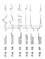
- Figs. 3A to 3F are timing charts showing the operations of the system as illustrated in Fig. 2.
- Fig. 4 is a block diagram showing another embodiment of the servo control system according to the present invention.
- Fig. 2 is a block diagram showing an embodiment of the servo control system according to the present invention, which is applied to a tracking servo control system adapted to cause the data read/write optical head to follow the target track formed on rotating record media such as an optical disk which rotates at a constant speed.
- identical elements are designated by the same references as those in the conventional system, of which description will hence be omitted.
- the reference numeral 5 is a disturbance signal generator which generates a disturbance signal in synchronism with a digital compensator 2.
- the disturbance signal generated hereat is applied to the control output of the digital compensator 2.
- a drive circuit 3 identifies or adjusts the respective parameters for the drive circuit 3, an actuator 4, and a tracking error detector 1 as will be described later, in the state where the actuator 4 is compulsorily vibrated while applying the disturbance signal to the control signal.
- the operation of the disturbance signal generator 5 is controlled by a CPU not shown, and generates the disturbance signal only at the time of identifying parameters. Identity of the parameters may be carried out when the record medium is replaced or electric power is supplied, or may be periodically performed at regular intervals of time. Furthermore, in the present invention, the disturbance signal is generated through a software in the form of the M sequence signal (Maximum length linearly recurring sequence signal) having the predetermined amplitude.
- a parameter identifier 6 accomplishes identity of the controlled parameters through a software processing on the basis of the tracking error signal which is detected by the tracking error detector 1, and the control signal of the digital compensator 2 to which the disturbance signal is applied.
- the digital compensator 2 is then updated in accordance with the result thus obtained.
- algorithm for the parameters identification for example, the method of least squares is known, which will be described later in more detail.
- the deviation between the optical head driven by the actuator 4 and target track is detected by the tracking error detector 1, and output in the form of tracking error signals at every predetermined period as shown in Fig. 3A.
- the digital compensator 2 computes required values at every predetermined interval of time as shown in Fig. 3B in such a manner that the optical head can be positioned on the target track in compliance with the tracking error signal, and outputs a control signal.
- the disturbance signal generator 5 outputs the M sequence signal having the predetermined amplitude as shown in Fig. 3C in synchronism with the digital compensator 2.
- the sum of this M sequence signal which is output in the form of disturbance signal and the digital compensator 2 is output to the drive circuit 3 as a control input.
- the drive circuit 3 drives the actuator 4 based on the resultant control input, thus causing the actuator 4 to vibrate through the disturbance signal as stated above.
- a parameter identification start signal as shown in Fig. 3D is output to the parameter identifier 6 through the CPU not shown.
- the parameter identifier 6 identifies the respective parameters by use of the tracking error signal and the foregoing control input. In other words, the parameter identification is carried out with respect to the discrete system dynamic characteristics composed of the drive circuit 3, the actuator 4, and the tracking error detector 1. Based on the results, the digital compensator 2 is then updated.
- Fig. 3E shows the first output of the parameter identifier 6, while Fig. 3F shows the N-th output of the same, in which N parameters in the digital compensator 2 can be identified through outputs of the parameter identifier 2.
- the output of the tracking error detector 1 and the output of the digital compensator 2 include a rotational frequency component resulting from eccentricity of the disk-like record medium and the frequency component by integral times thereof.
- the optical head deviates periodically relative to the target track due to the foregoing frequency component. That is, the periodic disturbance arising from eccentricity of the record medium is introduced into the control system, to cause the optical head to be displaced relative to the target track.
- the result of the parameter identification may be quite different from the true value due to the periodic disturbance. Therefore, the rotation of the record medium must be stopped in case of the parameter identification.
- Fig. 4 is therefore a functional block diagram equivalent to it in view of its hardware.
- the first filter 7 and the second filter 8 are digital filters which operate in synchronism with the digital compensator 2.
- the sampling period of the digital compensator 2 is determined by the sampling period of the tracking error detector 1, and the latter is set so as to have the following relationship with the rotation period of the record medium:
- T nh [T designates a rotation period of a record medium, n an integer, and h a sampling period of the detecting means]
- the first filter 7 filters the outputs of the digital compensator 2 and the disturbance signal generator 5 to input it into the parameter identifier 6.
- the second filter 8 also filters the output of the tracking error detector 1 to input it into the parameter identifier 6.
- the first and second filters serve as filters which remove the rotational frequency component and its integral times frequency component of the record medium. In consequence, the signal input into the parameter identifier 6 is free from the frequency component of the periodic disturbance attributable to the eccentric of the record medium.
- the parameter identifier 6 identifies the respective parameters of the digital compensator 2 by use of the outputs of the first filter 7 and the second filter 8, thereby updating the digital compensator 2 based on the obtained result.
- the signal input into the parameter identifier 6 is free from the frequency component of the periodic disturbance as described above, so that it is not affected by the eccentricity of the record medium even though the record medium is in rotation.
- the recording medium need not be stopped every time parameter identity is carried out, to thereby enable the parameter identity with the record medium rotating in the operation mode of the system, leading to the great practical efficiency.
- the drive circuit 3, the actuator 4, and the tracking error detector 1 are regarded as one controlled object, the dynamic characteristics of which can be expressed by the following equation (a).
- A(z ⁇ 1)y(k) B(z ⁇ 1)u(k) + v(k) + r(k)
- A(z ⁇ 1) 1 + a1z ⁇ 1 + ... + a n z -n
- B(z ⁇ 1) b1z ⁇ 1 + ... + b n z -n
- k designates a time, y(k) a value of the tracking error signal at time k, u(k) a value of the control input (input of the drive circuit 3) at time k, and r(k) a equation error at time k.
- v(k) represents periodical displacement of the absolute position of the optical head relative to the target track at time k, which is caused by the rotation of the record medium.
- Z ⁇ 1 represents an operator showing delays, A(Z ⁇ 1) a denominator polynomial for the controlled object, and B(z ⁇ 1) a numerator polynomial for the controlled object.
- the period of v(k) is equal to the rotation period T of the record medium.
- the equation (c) would be established in virtue of the nature of the v(k).
- the equation (a) is transformed into the following equation (f) by use of the equations (c), (d) and (e).
- the coefficients for A(Z ⁇ 1), B(Z ⁇ 1) can be identified.
- the resultant coefficients for A(Z ⁇ 1) and B(Z ⁇ 1) identified in this manner are used to design the digital compensator 2 as follows.
- the digital compensator 2 which stabilizes the control system can be obtained.
- the digital compensator 2 optimizes the dynamic characteristics of the controlled object composed of the drive circuit 3, the actuator 4, and the tracking error detector 1.
- the correlation of the transfer characteristics is optimized at respective frequencies between the detection point on the servo loop of the tracking error signal used at the time of parameter identification, and the detection point of the input signal to the drive circuit 3 to which disturbance signal is applied.
- the filter is represented by the equation (b) by way of example, but the following equation (g) may be used instead.
- the filter may also have a function for lowering the high frequency component or the low frequency component as well as the function for lowering the rotational frequency component of the record medium.
- the above-mentioned equations (a) and (g) may be substituted by the following equations (h) and (i).
- F(z ⁇ 1) denotes a filter having a low-pass property or a high-pass property, or a band-pass property.
- F(z ⁇ 1) 1 - z ⁇ 1
- direct-current component of the filter input signal can be attenuated.
- the digital filter is used as the first and the second filter, but an analogue filter may be used instead.
- an analogue filter may be used instead.
- disturbance signal not only M sequence signal but also Gaussian white noise or random numbers may be used. A rectangular wave signal is also acceptable.
- the disturbance signal may be produced by either software or hardware.
- the algorithm for parameter identification may be applied after the data input through the filters are temporarily stored together into the storage device such as semiconductor memory or disk.
- the serial algorithm for identifying the parameters may be also applied to the data which is input from the filters in synchronism with the digital compensator.
- the transfer characteristics which is referred to in the present invention means the frequency characteristics, which shows how the ratio of amplitude at the output to that at the input of the control system, and the phase shift would be varied in accordance with the frequency.
- the parameters of the control means for controlling the head are so adjusted that a precise control can be always carried out relative to the target track despite the secular change of the actuator or the environmental change.
- the filters are used to attenuate the given frequency component including the rotational frequency component of the record medium, thus eliminating the affection of rotation caused by the rotating record medium, to consequently ensure the precise identification of the parameters.
Landscapes
- Optical Recording Or Reproduction (AREA)
Applications Claiming Priority (4)
| Application Number | Priority Date | Filing Date | Title |
|---|---|---|---|
| JP3388890A JP2593230B2 (ja) | 1990-02-16 | 1990-02-16 | ディスク駆動装置 |
| JP33888/90 | 1990-02-16 | ||
| JP8849/91 | 1991-01-29 | ||
| JP884991A JPH04252474A (ja) | 1991-01-29 | 1991-01-29 | 情報記録再生装置 |
Publications (3)
| Publication Number | Publication Date |
|---|---|
| EP0442751A2 true EP0442751A2 (de) | 1991-08-21 |
| EP0442751A3 EP0442751A3 (en) | 1991-11-13 |
| EP0442751B1 EP0442751B1 (de) | 1996-05-15 |
Family
ID=26343450
Family Applications (1)
| Application Number | Title | Priority Date | Filing Date |
|---|---|---|---|
| EP19910301231 Expired - Lifetime EP0442751B1 (de) | 1990-02-16 | 1991-02-15 | Servosteuerungssystem |
Country Status (2)
| Country | Link |
|---|---|
| EP (1) | EP0442751B1 (de) |
| DE (1) | DE69119443T2 (de) |
Citations (2)
| Publication number | Priority date | Publication date | Assignee | Title |
|---|---|---|---|---|
| EP0256842A2 (de) * | 1986-08-12 | 1988-02-24 | Kabushiki Kaisha Toshiba | Adaptives Prozessregelungssystem |
| EP0335650A2 (de) * | 1988-03-31 | 1989-10-04 | International Business Machines Corporation | Bewertetes Servo-Kontrollsystem zur Bewegungsregelung |
-
1991
- 1991-02-15 EP EP19910301231 patent/EP0442751B1/de not_active Expired - Lifetime
- 1991-02-15 DE DE1991619443 patent/DE69119443T2/de not_active Expired - Fee Related
Patent Citations (2)
| Publication number | Priority date | Publication date | Assignee | Title |
|---|---|---|---|---|
| EP0256842A2 (de) * | 1986-08-12 | 1988-02-24 | Kabushiki Kaisha Toshiba | Adaptives Prozessregelungssystem |
| EP0335650A2 (de) * | 1988-03-31 | 1989-10-04 | International Business Machines Corporation | Bewertetes Servo-Kontrollsystem zur Bewegungsregelung |
Non-Patent Citations (1)
| Title |
|---|
| ADVANCES IN INSTRUMENTATION. vol. 37, no. 3, 1982, PITTSBURGH US pages 1353 - 1362; K.nagakawa et al: "An Auto-tuning PID Controller" * |
Also Published As
| Publication number | Publication date |
|---|---|
| DE69119443T2 (de) | 1996-10-02 |
| EP0442751B1 (de) | 1996-05-15 |
| EP0442751A3 (en) | 1991-11-13 |
| DE69119443D1 (de) | 1996-06-20 |
Similar Documents
| Publication | Publication Date | Title |
|---|---|---|
| US6434096B1 (en) | Optical information recording/reproducing device | |
| CA2355747C (en) | Apparatus and method of compensating for disturbance using learning control in optical recording/reproducing apparatus and optical recording medium drive servo system using the apparatus and method | |
| US7042827B2 (en) | Disk drive servo system for eccentricity compensation and method thereof | |
| US5233586A (en) | Servo control system for controlling tracking of an optical head on an optical disk | |
| US7274640B2 (en) | Apparatus and method for determining disc type | |
| JPS626445A (ja) | 光ピツクアツプのトラツキング制御方式 | |
| CA2200286C (en) | Tracking control apparatus and method | |
| US4918680A (en) | Focus-servo correction utilizing storage of detected focus errors | |
| KR100540094B1 (ko) | 디스크 장치 | |
| JPS60246026A (ja) | 光学的再生装置用のサ−ボ誤差減少装置 | |
| KR100400045B1 (ko) | 외란 제거 장치 및 방법 | |
| US6153998A (en) | Method of controlling a two-degree-of-freedom control system | |
| EP0442751A2 (de) | Servosteuerungssystem | |
| US6785205B2 (en) | Apparatus for controlling eccentricity in photo-record player and control method thereof | |
| JP2003085905A (ja) | 情報記録及び/又は再生装置の共振周波数測定方法、及び、情報記録及び/又は再生装置並びにフィルタ | |
| EP0504300B1 (de) | Spursteuersystem für eine optische aufnahme- und abtasteinheit | |
| KR100498455B1 (ko) | 서보 시스템의 루프이득을 제어하기 위한 장치 및 방법 | |
| JP2593230B2 (ja) | ディスク駆動装置 | |
| EP0442712B1 (de) | Optisches Informationsaufzeichnungs- und/oder Wiedergabegerät | |
| JPH11213403A (ja) | トラッキングサーボ方法及び光ディスク装置 | |
| KR970011816B1 (ko) | 리드/래그 보상기 설계방법 | |
| KR100486277B1 (ko) | 포커스 서치 장치 및 포커스 서치 방법 | |
| JPH04252474A (ja) | 情報記録再生装置 | |
| JP2718053B2 (ja) | フォーカスサーボのゲイン調整装置 | |
| JPH10241177A (ja) | 光ディスク装置 |
Legal Events
| Date | Code | Title | Description |
|---|---|---|---|
| PUAI | Public reference made under article 153(3) epc to a published international application that has entered the european phase |
Free format text: ORIGINAL CODE: 0009012 |
|
| AK | Designated contracting states |
Kind code of ref document: A2 Designated state(s): DE FR GB IT NL |
|
| PUAL | Search report despatched |
Free format text: ORIGINAL CODE: 0009013 |
|
| AK | Designated contracting states |
Kind code of ref document: A3 Designated state(s): DE FR GB IT NL |
|
| 17P | Request for examination filed |
Effective date: 19920401 |
|
| 17Q | First examination report despatched |
Effective date: 19940722 |
|
| GRAH | Despatch of communication of intention to grant a patent |
Free format text: ORIGINAL CODE: EPIDOS IGRA |
|
| GRAA | (expected) grant |
Free format text: ORIGINAL CODE: 0009210 |
|
| AK | Designated contracting states |
Kind code of ref document: B1 Designated state(s): DE FR GB IT NL |
|
| REF | Corresponds to: |
Ref document number: 69119443 Country of ref document: DE Date of ref document: 19960620 |
|
| ITF | It: translation for a ep patent filed | ||
| ET | Fr: translation filed | ||
| PLBE | No opposition filed within time limit |
Free format text: ORIGINAL CODE: 0009261 |
|
| STAA | Information on the status of an ep patent application or granted ep patent |
Free format text: STATUS: NO OPPOSITION FILED WITHIN TIME LIMIT |
|
| 26N | No opposition filed | ||
| REG | Reference to a national code |
Ref country code: GB Ref legal event code: IF02 |
|
| PGFP | Annual fee paid to national office [announced via postgrant information from national office to epo] |
Ref country code: NL Payment date: 20090217 Year of fee payment: 19 Ref country code: DE Payment date: 20090228 Year of fee payment: 19 |
|
| PGFP | Annual fee paid to national office [announced via postgrant information from national office to epo] |
Ref country code: GB Payment date: 20090218 Year of fee payment: 19 |
|
| PGFP | Annual fee paid to national office [announced via postgrant information from national office to epo] |
Ref country code: IT Payment date: 20090205 Year of fee payment: 19 |
|
| PGFP | Annual fee paid to national office [announced via postgrant information from national office to epo] |
Ref country code: FR Payment date: 20090223 Year of fee payment: 19 |
|
| REG | Reference to a national code |
Ref country code: NL Ref legal event code: V1 Effective date: 20100901 |
|
| GBPC | Gb: european patent ceased through non-payment of renewal fee |
Effective date: 20100215 |
|
| REG | Reference to a national code |
Ref country code: FR Ref legal event code: ST Effective date: 20101029 |
|
| PG25 | Lapsed in a contracting state [announced via postgrant information from national office to epo] |
Ref country code: NL Free format text: LAPSE BECAUSE OF NON-PAYMENT OF DUE FEES Effective date: 20100901 Ref country code: FR Free format text: LAPSE BECAUSE OF NON-PAYMENT OF DUE FEES Effective date: 20100301 |
|
| PG25 | Lapsed in a contracting state [announced via postgrant information from national office to epo] |
Ref country code: DE Free format text: LAPSE BECAUSE OF NON-PAYMENT OF DUE FEES Effective date: 20100901 |
|
| PG25 | Lapsed in a contracting state [announced via postgrant information from national office to epo] |
Ref country code: IT Free format text: LAPSE BECAUSE OF NON-PAYMENT OF DUE FEES Effective date: 20100215 Ref country code: GB Free format text: LAPSE BECAUSE OF NON-PAYMENT OF DUE FEES Effective date: 20100215 |