EP0441919B1 - Furniture unit for installation in a right-angled corner of a room - Google Patents
Furniture unit for installation in a right-angled corner of a room Download PDFInfo
- Publication number
- EP0441919B1 EP0441919B1 EP90911989A EP90911989A EP0441919B1 EP 0441919 B1 EP0441919 B1 EP 0441919B1 EP 90911989 A EP90911989 A EP 90911989A EP 90911989 A EP90911989 A EP 90911989A EP 0441919 B1 EP0441919 B1 EP 0441919B1
- Authority
- EP
- European Patent Office
- Prior art keywords
- frame
- unit
- guide
- built
- furniture
- Prior art date
- Legal status (The legal status is an assumption and is not a legal conclusion. Google has not performed a legal analysis and makes no representation as to the accuracy of the status listed.)
- Expired - Lifetime
Links
Images


Classifications
-
- A—HUMAN NECESSITIES
- A47—FURNITURE; DOMESTIC ARTICLES OR APPLIANCES; COFFEE MILLS; SPICE MILLS; SUCTION CLEANERS IN GENERAL
- A47B—TABLES; DESKS; OFFICE FURNITURE; CABINETS; DRAWERS; GENERAL DETAILS OF FURNITURE
- A47B57/00—Cabinets, racks or shelf units, characterised by features for adjusting shelves or partitions
- A47B57/06—Cabinets, racks or shelf units, characterised by features for adjusting shelves or partitions with means for adjusting the height of the shelves
- A47B57/16—Cabinets, racks or shelf units, characterised by features for adjusting shelves or partitions with means for adjusting the height of the shelves consisting of hooks coacting with openings
-
- A—HUMAN NECESSITIES
- A47—FURNITURE; DOMESTIC ARTICLES OR APPLIANCES; COFFEE MILLS; SPICE MILLS; SUCTION CLEANERS IN GENERAL
- A47B—TABLES; DESKS; OFFICE FURNITURE; CABINETS; DRAWERS; GENERAL DETAILS OF FURNITURE
- A47B81/00—Cabinets or racks specially adapted for other particular purposes, e.g. for storing guns or skis
- A47B81/002—Corner cabinets; Cabinets designed for being placed in a corner or a niche
Definitions
- the invention relates to a furniture unit according to the preamble of independent claim 1.
- the walls that enclose an angle of 90 °, for example, should also be covered with furniture.
- the corner room often remains unused because the furniture pieces attached to the two walls would at least partially inaccessible furniture filling this corner room.
- a furniture unit which avoids this inaccessibility and is intended for installation in a rectangular corner of a room has been described in CH-A-593 657.
- This known furniture unit has two horizontally displaceable built-in elements, the outer built-in element being pullable out of the base body and pivotable about a vertical one from the corner of the room.
- the two sliding installation elements are connected to one another by levers so that when the outer installation element is pivoted about the vertical axis, the installation element located in the corner is displaced horizontally within the base body and in the direction of the same to the place that was originally occupied by the swiveled-out installation element is.
- the built-in elements used in the known version each contain a body that can be cut. The interior of the body must be used to store those in the furniture unit Objects equipped with storage elements, for example in the form of shelves or wire mesh baskets.
- the body can be formed, for example, from a wooden box open on the front or from a welded steel frame.
- the known design of a furniture element for installation in the corner of a room has disadvantages, in particular due to the size and the spatial expansion of the body. These disadvantages mainly concern the installation of the device, but also its flexibility with regard to its use in furniture of different dimensions and designs.
- the body is designed as a spatially relatively bulky part which is to be inserted into the pre-assembled furniture unit, fastened there and connected to the lever system.
- the guides can be tilted. This can make the horizontally displaceable built-in elements difficult to move and thus impair the function of the furniture unit.
- the known furniture unit is hardly suitable for such applications as are e.g. resulting from sales through do-it-yourself retailers.
- the invention is therefore based on the object of creating a furniture unit for installation in a corner of a room, the manufacture and assembly being considerably simplified and accelerated and the risk of canting of the horizontally displaceable installation elements being eliminated as far as possible. In doing so, if possible even simpler parts than those used in the known solution are used.
- Another object of the invention is to design the fittings used for the sliding device in such a way that their use is possible in a large number of differently designed pieces of furniture.
- the device should be adaptable to different dimensions and designs of built-in wardrobes depending on the country-specific standard, or together with different cover plates, e.g. Granite slabs can be used. This is achieved in particular by the special design of the guide frame in the first embodiment of the invention.
- the installation elements are essentially designed such that the storage elements are suspended on one side in a flat frame after all other components have been installed.
- This displaceable flat frame hereinafter referred to as the running frame, is mounted horizontally displaceably on an equally flat guide frame.
- the body is no longer designed as a part with a spatial extension.
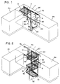
- a base body 1 for example a wooden body, is installed in a corner of a room.
- a number of storage elements are located within the base body 14 having built-in elements 3, 4, wherein for reasons of clarity only the inner built-in element 3 is provided with a single storage element 14.
- the remaining storage elements 14 which can be used on the inner installation element 3 and on the outer installation element 4 are not shown.
- Any other furniture elements 2a, 2b are connected to the base body 1. Due to the vicinity of the transversely connecting element 2a, the inner built-in element 3 would not be accessible from the outside in a conventional furniture unit.
- a lever mechanism has been proposed in CH-A-593 657, with which an inevitable displacement of the inner installation element 3 is possible if the outer installation element 4, after it has been pulled out of the base body 1, then about a vertical axis is pivoted.
- This known lever device is also used in the present invention.
- Fig. 1 the angled lever 50 can be seen, which is attached so that it forms a kinematic chain when interacting with the connecting lever 60, via which a displacement of the inner mounting element 3 is achieved to the externally accessible space when the outer Installation element 4 is pivoted about the vertical axis 100.
- the invention provides that the running frame 80 of the outer installation element 4, which has just been executed, is attached to a pivotable guide unit 90 so as to be longitudinally displaceable.
- the pivotable guide unit 90 receiving the moving frame 80 of the outer installation element 4 is attached to the side facing away from the inner installation element 3, and is in turn by means of the vertical one Hinge joints 101 forming the pivot axis 100 are connected to the base body 1.
- a flat guide frame 70 is arranged vertically in the rear part of the furniture unit.
- This guide frame 70 has running rails which have the task of guiding the running frame 120 of the inner installation element 3 so that it can be moved horizontally. The movements are coupled via the two levers 50, 60.
- FIG. 2 shows the furniture unit according to the invention in such a state that it assumes when the outer installation element 4 is pulled out of the base body 1 and pivoted about the vertical axis 100.
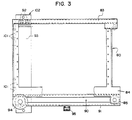
- Fig. 3 is a side view of the running frame of the outer installation element 4 in the closed state of the furniture unit, i.e. the running frame 80 is in the pivoted-in and pushed-in state.
- the figure shows another possible embodiment of the design of the pivotable guide unit 90 and the guides for the sliding movement of the running frame 80 relative to the guide unit.
- the upper rail 83 of the running frame 80 is guided only by means of the pivotable guide unit 90 Guide rollers 92.
- the vertical part 93 of the pivotable guide unit 90 is attached to the fixed support unit 102.
- a running roller 85 is provided, which runs on the rail part 91 of the pivotable guide unit 90 rolls.
- the pivotable guide unit 90 is provided with a further roller 94, on which the lower rail 84 of the frame 80 rolls when it is pulled out of the base body.
- the rail part 91 of the pivotable guide unit 90 is provided on the lower edge with a slider 95, which serves to drive the pivoting movement of the angled lever 50 in a manner known per se. It is clear from the illustration in FIG. 3 that the roller 85 present at the corner of the running frame 80 is moved in the direction of the running roller 94 connected to the guide element 90 when the running frame 80 is pulled out, the mentioned running roller 94 initially opposite the base body remains stationary.
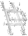
- Fig. 4 is a perspective view of the main components of the inner mounting member.
- the running frame 120 is essentially formed by the vertical struts 121 and the horizontal struts 123, 124.
- the vertical struts 121 are each provided on their front side at the same height with a number of hooks 122, which are preferably arranged at a constant distance from one another.
- the storage elements (not shown) are attached after assembly is complete.
- the storage elements are designed, for example, in the form of baskets, bowl-shaped bodies or plate-shaped bodies made of flat steel wire elements. These are attached on one side to the respective running arms of the inner or outer installation element in such a way that they form a right angle with respect to the flat frame.
- the right-angled protrusion of the storage elements from the running frame is ensured in that the lower region of the storage elements is supported with respect to the frame.
- the storage elements have a certain height, ie a sufficient distance between the parts interacting with the hooks 122 and their lower part.
- FIG. 6 Another embodiment of the attachment of the storage elements 14 relative to the respective moving frame is shown in FIG. 6.
- the respective moving frame is provided with holes into which the respective fastening elements of the storage element 14 are hung.
- the principle of this hanging is known as such and can be seen from the illustration in FIG. 6.
- the embodiment of the attachment of the storage elements 14 shown in FIG. 6 can also be used in the case of the embodiment of the running frame shown in FIG. 4.
- the running frame 80 of the outer installation element shown in FIG. 3 the latter is provided with bores in order, for example, to accommodate storage elements according to the embodiment shown in FIG. 6.
- the embodiment of the attachment of the storage elements relative to the running frame based on the use of hook-shaped fastening elements according to FIG. 6 can also be used in this exemplary embodiment.
- the one-sided suspension of the storage elements 14 on the respective running frame is a basic requirement for the inventive design of the respective running frame as a flat component.
- excellent handling and flexibility of the storage elements is ensured as a result of the possible types of fastening of the storage elements.
- the storage elements can be easily replaced or, in order to be able to carry out cleaning work, for example, simply removed. This provides easy access to the installation elements.
- the horizontal struts 123, 124 of the running frame 120 which can be seen in FIG. 4 are equipped on the rear side with a number of guide rollers 125, 126, 127, which have the task of guiding the running frame 120 in a longitudinally displaceable manner relative to the fixed guide frame 70.
- the fixed guide frame 70 comprises two struts 71 which run at a corresponding distance from one another in the horizontal direction and which serve as rails for rollers present on the running frame 120. At the rear, these rails 71 are connected to one another by means of two vertically extending connecting struts 72. On the underside, these connecting struts 72 are equipped with support feet 73 which can be fastened to the floor. For fixing these support feet 73 on the floor are preferably provided with through holes.
- the rails 71 are each provided with support arms 75 at their ends.
- the support arms 75 end with flange plates 76, which in turn are preferably provided with through holes for wall mounting.
- the support arms 75 are each guided in a sleeve 74, so that the former can be displaced in the direction of the rails 71.
- the sleeves 74 are each equipped with a threaded hole in which a clamping screw 77 is provided.
- the inner cross-section of the sleeves 74 has a preferably rectangular cross-sectional shape corresponding to the outer cross-section of the support arms 75, and the sleeves 74 are each attached at the end of the rail 71 to the rear side thereof, preferably by welding.
- the cross section of the sleeves 74 preferably corresponds to that of the connecting struts 72, or at least their inner cross section also corresponds to the outer cross section of the support arms 75.
- the fixed guide frame 70 could, for example, be fastened to the floor, to a side wall (right or left) and to the cover plate which closes the furniture unit upwards.
- FIG. 5 a side view of the components shown in the previous FIG. 4 is given, which, however, are in the functional, assembled state in FIG. 5.
- the running frame 120 of the inner installation element is formed by the struts 121, 123 and 124, the horizontal struts 123, 124 carrying the corresponding running rollers 125, 126, 127.
- the pairs of rollers 125, 126 are horizontal Direction oriented, ie they rotate around vertical axes. In connection with their arrangement in the respective rail 71, it is clear that these pairs of rollers 125, 126 rotating about vertical axes take over the guidance of the running frame 120 in the horizontal direction. It goes without saying that the diameter of the rollers 125, 126 has to be slightly smaller than the inner width of the profiles 71. In this way it is ensured that the horizontal guidance of the running frame 120 takes place with as little play as possible and, on the other hand, on the rail / roller -Pairing no sliding friction arises.
- the vertical guidance of the running frame 120 with respect to the fixed guide frame 70 takes place by means of the pair of rollers 127.
- the roller 127 shown in FIG. 5 is arranged in the vertical direction, i.e. it rotates about a horizontal axis connected to the lower horizontal strut 124. This roller 127 rolls on the upper surface of the lower rail 71.
- the assembly of the running frame 120 on the guide frame 70 preferably has to be carried out before the latter is installed in the base body in such a way that the running frame 120 is pushed onto the rails 71 from one end thereof.
- assembly of the running frame 120 is in principle also possible in such a way that the rollers of one side of the running frame 120, for example the left side, are pushed onto the corresponding, for example also left end of the rails 71, and then the Unilaterally mounted moving frame to the other, so the right end of the guide frame 70 moved and there the roles of the others Side of the running frame are pushed onto the rails 71 of the guide frame 70 from its corresponding side.
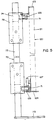
- FIG. 6 shows a further embodiment with regard to the design of the inner built-in element from largely flat components.
- the guidance of the running frame of the inner built-in element by means of a fixed guide frame arranged vertically in the rear area of the furniture element in the embodiment to be described now the guide frame is arranged horizontally in the upper area of the furniture element.
- the guide frame 7 consists of a pair of rails 7b which are connected to one another by means of connecting struts 7a.
- the running frame 12 is designed as a two-part unit, consisting of a carriage 12a and a support frame 13, to which the storage elements 14 can be attached.
- the carriage 12a which can be moved in the rails 7 via rollers 15 consists of a frame formed from a pair of longitudinal struts 16 and transverse struts 17 and a diagonal strut 17a, from which vertical struts 18 extend downward at the rear edge.
- the lower end of the vertical struts 18 is connected by means of support struts 19 to the front region of the frame, ie to the front region of the cross struts 17, for the purpose of absorbing bending moments acting on the vertical struts 18.
- the vertical struts 18 of the carriage 12a are preferably formed from L-profiles and welded to the frame formed from the longitudinal and transverse struts 16, 17.
- the vertical struts 18 are each in the upper region with a bore running in the longitudinal direction of the rail 7b 20 provided.
- Support bolts 21 are each firmly connected to the upper end of the support frame 13 of the inner installation element, for example welded. The distance between the two vertical struts 18 is dimensioned such that the support frame 13 finds space just between the L-profiles. After the mounting frame has been installed, the support bolts 21 come into engagement with the bores 20 present in the vertical struts 18.
- the support frame 13 To mount the support frame 13, it is pressed together in the open upper area to such an extent that the outer ends of the support bolts 21 can be inserted into the bores 20 from the inside.
- the pressure on the support frame 13 decreases, it springs back and now hangs on the support bolt 21 which is supported in the bores 20 and its position is simultaneously fixed by the L-profiles of the vertical struts 18.
- the rear cheeks 18a of the L-profiles prevent the hanging support frame from pivoting backwards.
- FIG. 7 shows a plan view of a furniture unit according to the second embodiment of the invention, the cover plate of the furniture being removed.
- the state is shown in solid lines, in which the inner installation element 3 is in place and the outer installation element 4 is pulled out of the base body.
- the angled lever 50 can be pivoted about a pivot point 51 fixed on the base of the base body and on the side which is connected to the rail part 91 pivotable guide unit 90 is connected, formed as a guide 52. A with the rail part 91 connected slider 95 slides in this guide 52.
- the angled lever 50 is connected to a connecting lever 60, which in turn is articulated on the running frame of the inner installation element.
- a furniture unit for installation in a corner of a room can be designed with simpler means and fewer parts than before.
- the individual parts provided according to the invention are suitable for a large number of designs and dimensions of the piece of furniture, the assembly of the installation elements, which consist essentially of flat parts, is considerably simplified and the operational safety, i.e. Security against jamming and blocking of the moving elements, significantly increased.
Abstract
Description
Die Erfindung betrifft eine Möbeleinheit gemäss dem Oberbegriff des unabhängigen Patentanspruches 1.The invention relates to a furniture unit according to the preamble of independent claim 1.
Beim Innenausbau von Küchen, Büroräumen, Laboratorien oder dgl. sollen möglichst auch die Wände, die miteinander einen Winkel von beispielsweise 90° einschliessen, mit Möbeln besetzt werden. Dabei bleibt der Eckraum oftmals ungenutzt, weil durch die anschliessenden, an den beiden Wänden angestellten Möbelstücke ein diesen Eckraum ausfüllendes Möbel zumindest teilweise unzugänglich wäre.When installing kitchens, offices, laboratories, or the like, the walls that enclose an angle of 90 °, for example, should also be covered with furniture. The corner room often remains unused because the furniture pieces attached to the two walls would at least partially inaccessible furniture filling this corner room.
Eine diese Unzugänglichkeit vermeidende Möbeleinheit zum Aufstellen in einer rechtwinkligen Ecke eines Raumes ist in der CH-A-593 657 beschrieben worden. Diese bekannte Möbeleinheit weist zwei horizontal verschiebbare Einbauelemente auf, wobei das aussenliegende Einbauelement aus dem Grundkörper herausziehbar und um eine senkrechte von der Ecke des Raumes weg schwenkbar ist. Die beiden verschiebbaren Einbauelemente sind mit Hebeln untereinander so verbunden, dass beim Schwenken des äusseren Einbauelementes um die senkrechte Achse das in der Ecke befindliche Einbauelement innerhalb des Grundkörpers und in Richtung desselben horizontal bis zu dem Platz verschoben wird, welcher ursprünglich von dem herausgeschwenkten Einbauelement eingenommenen worden ist. Die in der bekannten Ausführung eingesetzten Einbauelemente beinhalten jeweils einen versc.hiebbaren Korpus. Das Innere des Korpus ist zur Aufnahme der in der Möbeleinheit aufzubewahrenden Gegenstände mit Ablageelementen, beispielsweise in Form von Regalbrettern oder Drahtgeflechtkörben ausgestattet. Der Korpus kann beispielsweise aus einem an der Vorderseite offenen Holzkasten oder aus einem geschweissten Stahlrahmen gebildet sein.A furniture unit which avoids this inaccessibility and is intended for installation in a rectangular corner of a room has been described in CH-A-593 657. This known furniture unit has two horizontally displaceable built-in elements, the outer built-in element being pullable out of the base body and pivotable about a vertical one from the corner of the room. The two sliding installation elements are connected to one another by levers so that when the outer installation element is pivoted about the vertical axis, the installation element located in the corner is displaced horizontally within the base body and in the direction of the same to the place that was originally occupied by the swiveled-out installation element is. The built-in elements used in the known version each contain a body that can be cut. The interior of the body must be used to store those in the furniture unit Objects equipped with storage elements, for example in the form of shelves or wire mesh baskets. The body can be formed, for example, from a wooden box open on the front or from a welded steel frame.
Die bekannte Ausführung eines Möbelelementes zum Aufstellen in der Ecke eines Raumes weist insbesondere durch die Grösse und die räumliche Ausdehnung des Korpus bedingt Nachteile auf. Diese Nachteile betreffen vor allem die Montage der Einrichtung, aber auch deren Flexibilität bezüglich des Einsatzes in Möbeln unterschiedlicher Abmessungen und Ausführung. Der Korpus ist als ein räumlich relativ sperriges Teil ausgeführt, welches in die bereits vormontierte Möbeleinheit einzusetzen, dort zu befestigen und mit dem Hebelsystem zu verbinden ist. Infolge Ungenauigkeiten bei der Fertigung bzw. infolge bei der Montage verursachten Verzuges des Korpus kann es zu Verkantungen in den Führungen kommen. Damit können die horizontal verschiebbaren Einbauelemente schwergängig und so die Funktion der Möbeleinheit beeinträchtigt werden. Darüberhinaus.eignet sich die bekannte Möbeleinheit insbesondere aufgrund ihrer Abmessungen, aber auch aufgrund ihrer mangelnden Flexibilität und Anpassbarkeit kaum für solche Anwendungsmöglichkeiten, wie sie sich z.B. durch den Vertrieb über den do-it-yourself-Fachhandel ergeben.The known design of a furniture element for installation in the corner of a room has disadvantages, in particular due to the size and the spatial expansion of the body. These disadvantages mainly concern the installation of the device, but also its flexibility with regard to its use in furniture of different dimensions and designs. The body is designed as a spatially relatively bulky part which is to be inserted into the pre-assembled furniture unit, fastened there and connected to the lever system. As a result of inaccuracies in production or as a result of warping of the body caused during assembly, the guides can be tilted. This can make the horizontally displaceable built-in elements difficult to move and thus impair the function of the furniture unit. In addition, due to its dimensions, but also due to its lack of flexibility and adaptability, the known furniture unit is hardly suitable for such applications as are e.g. resulting from sales through do-it-yourself retailers.
Der Erfindung liegt deswegen die Aufgabe zugrunde, eine Möbeleinheit zum Aufstellen in einer Ecke eines Raumes zu schaffen, wobei die Fertigung und Montage wesentlich vereinfacht und beschleunigt werden und die Gefahr von Verkantungen der horizontal verschiebbaren Einbauelemente möglichst ausgeschlossen werden soll. Dabei sollen möglichst noch einfachere Teile als die bei der bekannten Lösung verwendeten zum Einsatz kommen.The invention is therefore based on the object of creating a furniture unit for installation in a corner of a room, the manufacture and assembly being considerably simplified and accelerated and the risk of canting of the horizontally displaceable installation elements being eliminated as far as possible. In doing so, if possible even simpler parts than those used in the known solution are used.
Die Aufgabe wird erfindungsgemäss durch die im kennzeichnenden Teil des Patentanspruches 1 aufgeführten Merkmale gelöst.The object is achieved by the features listed in the characterizing part of claim 1.
Eine weitere Aufgabe der Erfindung besteht darin, die verwendeten Beschläge für die Verschiebevorrichtung so zu gestalten, dass deren Verwendung in einer Vielzahl unterschiedlich beschaffener Möbel möglich ist. So soll die Vorrichtung beispielsweise an je nach landesspezifischer Norm verschiedene Abmessungen und Ausführungen von Einbauschränken anpassbar sein, oder zusammen mit unterschiedlichen Abdeckplatten wie z.B. Granitplatten verwendbar sein. Dies wird insbesondere durch die besondere Gestaltung des Führungsrahmens in der ersten Ausführung der Erfindung erreicht.Another object of the invention is to design the fittings used for the sliding device in such a way that their use is possible in a large number of differently designed pieces of furniture. For example, the device should be adaptable to different dimensions and designs of built-in wardrobes depending on the country-specific standard, or together with different cover plates, e.g. Granite slabs can be used. This is achieved in particular by the special design of the guide frame in the first embodiment of the invention.
Im folgenden wird die Erfindung, unter Bezugnahme auf die Zeichnungen beispielsweise näher erläutert. Dabei zeigen
- Fig. 1
- eine schematische perspektivische Darstellung einer erfindungsgemässen Möbeleinheit im geschlossenen Zustand,
- Fig. 2
- eine schematische perspektivische Darstellung einer erfindungsgemässen Möbeleinheit, wobei das äussere Einbauelement herausgezogen und -geschwenkt ist,
- Fig. 3
- eine Ansicht auf den Laufrahmen des äusseren Einbauelementes,
- Fig. 4
- eine perspektivische Darstellung einer ersten Ausführung des inneren Einbauelementes mit zugehörigem Führungsrahmen,
- Fig. 5
- eine vergrösserte Seitenansicht der in Fig. 4 gezeigten ersten Ausführung,
- Fig. 6
- eine perspektivische Darstellung einer zweiten Ausführung des inneren Einbauelementes mit zugehörigem Führungsrahmen und Ablageelement,
- Fig. 7
- die Draufsicht auf eine erfindungsgemässe Möbeleinheit (ohne Deckplatte) gemäss der zweiten Ausführung, das äussere Einbauelement in ausgezogener Position; in strichpunktierter Line ist zusätzlich die ausgeschwenkte Stellung dargestellt.
- Fig. 1
- 1 shows a schematic perspective illustration of a furniture unit according to the invention in the closed state,
- Fig. 2
- 2 shows a schematic perspective illustration of a furniture unit according to the invention, the outer installation element being pulled out and pivoted,
- Fig. 3
- a view of the running frame of the outer installation element,
- Fig. 4
- 1 shows a perspective illustration of a first embodiment of the inner installation element with associated guide frame,
- Fig. 5
- 3 shows an enlarged side view of the first embodiment shown in FIG. 4,
- Fig. 6
- 2 shows a perspective illustration of a second embodiment of the inner installation element with associated guide frame and storage element,
- Fig. 7
- the top view of a furniture unit according to the invention (without cover plate) according to the second embodiment, the outer installation element in the extended position; the swiveled-out position is also shown in a dash-dotted line.
Gemäss der vorliegenden Erfindung sind die Einbauelemente im wesentlichen so ausgeführt, dass die Ablageelemente nach vollzogener Montage aller anderen Komponenten einseitig in einen ebenen Rahmen eingehängt werden. Dieser verschiebbare ebene Rahmen, im folgenden Laufrahmen genannt, ist an einem gleichfalls ebenen Führungsrahmen horizontal verschiebbar gelagert. Im Unterschied zu der bekannten, mit einem äquivalenten Hebelsystem ausgerüsteten Lösung ist der Korpus also nicht mehr als ein Teil mit einer räumlichen Ausdehnung ausgeführt.According to the present invention, the installation elements are essentially designed such that the storage elements are suspended on one side in a flat frame after all other components have been installed. This displaceable flat frame, hereinafter referred to as the running frame, is mounted horizontally displaceably on an equally flat guide frame. In contrast to the known solution, which is equipped with an equivalent lever system, the body is no longer designed as a part with a spatial extension.
In Fig. 1 ist eine erfindungsgemässe Möbeleinheit dargestellt. Ein Grundkörper 1, beispielsweise ein Holzkorpus, ist in einer Ecke eines Raumes eingebaut. Innerhalb des Grundkörpers befinden sich die jeweils eine Anzahl Ablageelemente 14 aufweisenden Einbauelemente 3, 4, wobei aus Gründen der Uebersichtlichkeit lediglich das innere Einbauelement 3 mit einem einzigen Ablageelement 14 versehen ist. Die übrigen, am inneren Einbauelement 3 sowie am äusseren Einbauelement 4 einsetzbaren Ablageelemente 14 sind nicht dargestellt. An den Grundkörper 1 schliessen sich weitere beliebige Möbelelemente 2a, 2b an. Bedingt durch die Nachbarschaft des quer anschliessenden Elementes 2a wäre das innere Einbauelement 3 bei einer herkömmlichen Möbeleinheit von aussen nicht zugänglich.1 shows a furniture unit according to the invention. A base body 1, for example a wooden body, is installed in a corner of a room. A number of storage elements are located within the
Aus diesem Grund ist in der CH-A-593 657 ein Hebelmechanismus vorgeschlagen worden, mit welchem eine zwangsläufige Verschiebung des inneren Einbauelementes 3 möglich ist, wenn das äussere Einbauelement 4, nachdem es aus dem Grundkörper 1 herausgezogen worden ist, anschliessend um eine vertikale Achse geschwenkt wird. Von dieser vorbekannten Hebeleinrichtung wird auch in der vorliegenden Erfindung Gebrauch gemacht. In Fig. 1 ist der abgewinkelte Hebel 50 zu erkennen, welcher so angebracht ist, dass er beim Zusammenwirken mit dem Verbindungshebel 60 eine kinematische Kette bildet, über welche eine Verschiebung des inneren Einbauelementes 3 auf den von aussen zugänglichen Platz erreicht wird, wenn das äussere Einbauelement 4 um die vertikale Achse 100 geschwenkt wird.For this reason, a lever mechanism has been proposed in CH-A-593 657, with which an inevitable displacement of the
Zu diesem Zweck sieht die Erfindung vor, dass der eben ausgeführte Laufrahmen 80 des äusseren Einbauelementes 4 an einer schwenkbaren Führungseinheit 90 längsverschiebbar angebracht ist. Die den Laufrahmen 80 des äusseren Einbauelementes 4 aufnehmende schwenkbare Führungseinheit 90 ist an der dem inneren Einbauelement 3 abgekehrten Seite angebracht, und ist ihrerseits mittels die vertikale Schwenkachse 100 bildender Scharniergelenke 101 mit dem Grundkörper 1 verbunden.For this purpose, the invention provides that the running
Für das innere Einbauelement 3 ist im rückwärtigen Teil der Möbeleinheit ein ebener Führungsrahmen 70 vertikal angeordnet. Dieser Führungsrahmen 70 verfügt über Laufschienen, welche die Aufgabe haben, den Laufrahmen 120 des inneren Einbauelementes 3 horizontal verschiebbar zu führen. Die Kopplung der Bewegungen geschieht über die beiden Hebel 50, 60.For the
In Fig. 2 ist die erfindungsgemässe Möbeleinheit in einem solchen Zustand dargestellt, den sie einnimmt, wenn das äussere Einbauelement 4 aus dem Grundkörper 1 herausgezogen und um die vertikale Achse 100 geschwenkt ist.2 shows the furniture unit according to the invention in such a state that it assumes when the
In Fig. 2 ist im unteren Teil der Zeichnung das Schienenteil 91 der schwenkbaren Führungseinheit 90 des äusseren Einbauelementes 4 zu erkennen, welche schwenkbare Führungseinheit 90 sich in dem gezeichneten Zustand in der um die vertikale Achse 100 um fast 90° geschwenkten Position befindet. Es ist selbstverständlich, dass der Laufrahmen 80 einschliesslich aller daran befestigten Elemente vor dem Ausführen der Schwenkbewegung der Führungseinheit 90 aus dem Grundelement 1 herausgezogen werden muss.2, in the lower part of the drawing, the
Bei dieser Längsverschiebung des Laufrahmens 80 ist dieser sowohl mittels des Schienenteils 91 der schwenkbaren Führungseinheit 90 als auch mittels des Schienenteils 103 der feststehenden Trageinheit 102 geführt. In Fig. 2 ist dieses feststehende Schienenteil 103 deutlich zu identifizieren. Ausserdem ist zu erkennen, dass die Schwenkbewegung des abgewinkelten Hebels 50 gemäss der bereits in der CH-593 657 beschriebenen Weise mittels des Schienenteils 91 der schwenkbaren Führungseinheit 90 angetrieben wird. Die Ablageelemente 14 des inneren Einbauelementes 3 sind nun infolge der Verschiebung auf den ursprünglich vom äusseren Einbauelement 4 eingenommenen Platz von der Vorderseite des Möbelelementes her zugänglich. Schliesslich ist ist Fig. 2 zu erkennen, dass der Laufrahmen 80 des äusseren Einbauelementes 4 mit vorzugsweise einstellbaren Befestigungsmitteln 81 versehen ist, um daran eine Abdeckfront 82 anzubringen.During this longitudinal displacement of the running
Fig. 3 ist eine Seitenansicht auf den Laufrahmen des äusseren Einbauelementes 4 im geschlossenen Zustand der Möbeleinheit, d.h. der Laufrahmen 80 befindet sich im eingeschwenkten und eingeschobenen Zustand. Die Figur zeigt eine weitere mögliche Ausführungsform der Gestaltung der schwenkbaren Führungseinheit 90 und der Führungen für die Verschiebebewegung des Laufrahmens 80 gegenüber der Führungseinheit. Im Unterschied zu der in Fig. 2 dargestellten Ausführungsform, bei welcher die feststehende Trageinheit 102 mit einem Schienenteil 103 ausgestattet ist, erfolgt in dem in Fig. 3 dargestellten Beispiel die Führung der oberen Schiene 83 des Laufrahmens 80 lediglich über an der schwenkbaren Führungseinheit 90 angebrachte Führungsrollen 92. Mittels der beiden Scharniergelenke 101 ist der vertikale Teil 93 der schwenkbaren Führungseinheit 90 gegenüber der feststehenden Trageinheit 102 angebracht.Fig. 3 is a side view of the running frame of the
Im Bereich des zum Inneren der Möbeleinheit gewandten Endes der unteren Schiene 84- des Laufrahmens 80 ist eine Laufrolle 85 vorgesehen, welche auf dem Schienenteil 91 der schwenkbaren Führungseinheit 90 abrollt. Am entgegengesetzten Ende, d.h. am dem zur Vorderseite der Möbeleinheit gewandten Ende ist die schwenkbare Führungseinheit 90 mit einer weiteren Laufrolle 94 versehen, auf welcher die untere Schiene 84 des Laufrahmens 80 beim Herausziehen desselben aus dem Grundkörper abrollt.In the region of the end of the lower rail 84- of the running
Das Schienenteil 91 der schwenkbaren Führungseinheit 90 ist an der Unterkante mit einem Gleitstück 95 versehen, welches in an sich bekannter Weise dem Antrieb der Schwenkbewegung des abgewinkelten Hebels 50 dient. Aus der Darstellung von Fig. 3 wird deutlich, dass die an der Ecke des Laufrahmens 80 vorhandene Laufrolle 85 beim Herausziehen des Laufrahmens 80 aus dem Grundkörper in Richtung auf die mit dem Führungselement 90 verbundene Laufrolle 94 bewegt wird, wobei die erwähnte Laufrolle 94 zunächst gegenüber dem Grundkörper ortsfest bleibt.The
Wie bereits erwähnt sind insbesondere bezüglich der Ausbildung der Führungen und Lagerungen des Laufrahmens 80 verschiedene Ausführungen möglich. Daneben können zusätzlich Mittel vorgesehen sein, um eine zwangsläufige Koordination der Bewegungen des Herausziehens und Schwenkens des Einbauelementes bewirken.As already mentioned, 80 different designs are possible, in particular with regard to the design of the guides and bearings of the running frame. In addition, means can also be provided in order to bring about an inevitable coordination of the movements of pulling out and pivoting the installation element.
Fig. 4 ist eine perspektivische Darstellung der wichtigsten Komponenten des inneren Einbauelementes. Der Laufrahmen 120 ist im wesentlichen durch die vertikalen Streben 121 und die horizontalen Streben 123, 124 gebildet. Die vertikalen Streben 121 sind an ihrer Vorderseite jeweils auf gleicher Höhe mit einer Anzahl von Haken 122 versehen, welche vorzugsweise jeweils in konstantem Abstand zueinander angeordnet sind. An diese Haken 122 werden nach vollendeter Montage die Ablageelemente (nicht dargestellt) angehängt. Die Ablageelemente sind beispielsweise in Form von aus Stahldrahtelementen flachen Körben, schalenförmigen Körpern oder plattenförmigen Körpern ausgeführt. Diese werden einseitig so an den jeweiligen Laufarmen des inneren bzw. des äusseren Einbauelementes angehängt, dass sie gegenüber dem ebenen Rahmen einen rechten Winkel bilden. Im Fall von an die in Fig. 4 gezeigte Ausführung der hakenförmigen Befestigungselemente 122 angehängten Stahldrahtkörbern ist das rechtwinklige Abstehen der Ablageelemente vom Laufrahmen dadurch gewährleistet, dass sich der untere Bereich der Ablageelemente gegenüber dem Rahmen abstützt. Für diese Abstützung ist es selbs:verständlich erforderlich, dass die Ablageelemente eine gewisse Höhe, d.h. einen ausreichenden Abstand zwischen den mit den Haken 122 zusammenwirkenden Teilen und ihrem Unterteil besitzen.Fig. 4 is a perspective view of the main components of the inner mounting member. The running
Eine andere Ausführung der Befestigung der Ablageelemente 14 gegenüber dem jeweiligen Laufrahmen ist in Fig. 6 gezeigt. Dabei ist der jeweilige Laufrahmen anstelle von hakenförmigen Elementen mit Bohrungen versehen, in welche die jeweiligen Befestigungselemente des Ablageelementes 14 eingehängt werden. Das Prinzip dieses Einhängens ist als solches bekannt und aus der Darstellung in Fig. 6 ersichtlich. Selbstverständlich ist die in Fig. 6 gezeigte Ausführung der Befestigung der Ablageelemente 14 gegenüber dem jeweiligen Laufrahmen auch im Falle der in Fig. 4 gezeigten Ausführung des Laufrahmens anwendbar. In der in Fig. 3 gezeigten Ausführung des Laufrahmens 80 des äusseren Einbauelementes ist dieser mit Bohrungen versehen, um beispielsweise Ablageelemente gemäss der in Fig. 6 gezeigten Ausführung aufzunehmen. Selbstverständlich lässt sich auch in diesem Ausführungsbeispiel die auf der Verwendung hakenförmiger Befestigungselemente gemäss Fig. 6 beruhende Ausführungsform der Anbringung der Ablageelemente gegenüber dem Laufrahmen anwenden.Another embodiment of the attachment of the
Die einseitige Aufhängung der Ablageelemente 14 an dem jeweiligen Laufrahmen ist eine Grundvoraussetzung für die erfindungsgemässe Gestaltung des jeweiligen Laufrahmens als ebenes Bauteil. Ueber den Umfang der erwähnten Vorteile der erfindungsgemässen Lösung hinaus ist in Folge dEr möglichen Befestigungsarten der Ablageelemente eine ausgezeichnete Handhabbarkeit und Flexibilität derselben gewährleistet. So lassen sich die Ablageelemente einfach auswechseln oder, um beispielsweise Reinigungsarbeiten vornehmen zu können, einfach herausnehmen. Damit ist auf einfache Weise eine gute Zugänglichkeit der Einbauelemente gegeben.The one-sided suspension of the
Die in Fig. 4 erkennbaren, horizontalen Streben 123, 124 des Laufrahmens 120 sind auf der Hinterseite mit einer Anzahl Führungsrollen 125, 126, 127 ausgestattet, welche die Aufgabe haben, den Laufrahmen 120 gegenüber dem feststehenden Führungsrahmen 70 längsverschiebbar zu führen.The horizontal struts 123, 124 of the running
Der feststehende Führungsrahmen 70 umfasst zwei in horizontaler Richtung in entsprechendem Abstand zueinander verlaufenden Streben 71, welche als Schienen für am Laufrahmen 120 vorhandene Rollen dienen. An der Hinterseite sind diese Schienen 71 mittels zweier vertikal verlaufender Verbindungsstreben 72 untereinander verbunden. An der Unterseite sind diese Verbindungsstreben 72 mit am Boden befestigbaren Stützfüssen 73 ausgestattet. Zur Befestigung dieser Stützfüsse 73 am Boden sind dieselben vorzugsweise mit Durchgangslöchern versehen.The fixed
Zur seitlichen Befestigung des feststehenden Führungsrahmens 70 sind die Schienen 71 jeweils an ihren Enden mit Stützarmen 75 versehen. Die Stützarme 75 enden mit Flanschplatten 76, welche wiederum vorzugsweise mit Durchgangslöchern versehen zur Wandbefestigung geeignet sind. Die Stützarme 75 sind jeweils in einer Hülse 74 geführt, so dass die erstgenannten in Richtung der Schienen 71 verschiebbar sind. Die Hülsen 74 sind jeweils mit einem Gewindeloch ausgerüstet, in welchem eine Klemmschraube 77 vorgesehen ist. Der Innenquerschnitt der Hülsen 74 besitzt eine dem Aussenquerschnitt der Stützarme 75 entsprechende, vorzugsweise rechteckige Querschnittsform und die Hülsen 74 sind jeweils am Ende der Schiene 71 an deren Rückseite vorzugsweise durch Schweissverbindung angebracht. Unter Einsatz der beschriebenen Konstruktion der Stützarme ist eine Einstellung derselben, d.h. eine Einstellung des Abstandes der Flanschplatten 76 gegenüber dem jeweiligen Ende der Schiene 71 möglich. Auf diese Weise wird eine gute Anpassbarkeit des Führungsrahmens 70 an die verschiedensten Einbauverhältnisse erreicht.For the lateral attachment of the fixed
Der Querschnitt der Hülsen 74 entspricht vorzugsweise dem der Verbindungsstreben 72, bzw. zumindest entspricht deren Innenquerschnitt ebenfalls dem Aussenquerschnitt der Stützarme 75. Dies hat erstens den Vorteil, dass beide Teile aus demselben Halbzeug gefertigt werden können und eröffnet darüberhinaus insbesondere die Alternative, dass ein Paar der Stützarme 75 auch in vertikaler Richtung innerhalb der Verbindungsstreben 72 aufnehmbar ist. Auf gleiche Weise wie bereits unter Bezugnahme auf die Hülsen 74 beschrieben worden ist, ist am oberen Bereich der Verbindungsstreben ein Gewindeloch vorhanden, um im Zusammenwirken mit einer Klemmschraube eine Einstellbarkeit der nach oben gerichtet eingesetzten Stützarme zu gewährleisten. Auf diese Weise wird ermöglicht, dass eine hinreichende Befestigung des feststehenden Führungsrahmens 70 auch dann vorgenommen werden kann, wenn die Einbauverhältnisse ein beidseitiges Anbringen der horizontal angeordneten Stützarme nicht ermöglichen. In einem solchen Fall könnte der Führungsrahmen 70 beispielsweise am Boden, an einer Seitenwand (rechts oder links) und der die Möbeleinheit nach oben abschliessenden Deckplatte befestigt werden.The cross section of the
Die Wirkungsweise der Führung des Laufrahmens 120 mit Hilfe der jeweils paarweise vorhandenen Rollen 125, 126, 127 gegenüber den Schienen 71 des Führungsrahmens 70 wird in Fig. 5 deutlich. In dieser Figur ist eine Seitenansicht auf die in der vorstehenden Fig. 4 dargestellten Komponenten angegeben, welche sich in Fig. 5 jedoch im funktionsbereiten, montierten Zustand befinden. Man erkennt wiederum den feststehenden Führungsrahmen 70, welcher im wesentlichen aus den horizontalen, als Schienen wirkenden Streben 71 und den vertikalen Verbindungsstreben 72 gebildet wird und nach unten in Form der Stützfüsse 73 endet. Der Laufrahmen 120 des inneren Einbauelementes wird durch die Streben 121, 123 und 124 gebildet, wobei die horizontal verlaufenden Streben 123, 124 die entsprechenden Laufrollen 125, 126, 127 tragen. Diese sind auf bekannte Weise, beispielsweise mittels stillstehender Achsen, drehbar mit der entsprechenden Strebe verbunden. Die Rollenpaare 125, 126 sind in horizontaler Richtung orientiert, d.h. sie rotieren um jeweils vertikal stehende Achsen. Im Zusammenhang mit ihrer Anordnung in der jeweiligen Schiene 71 wird deutlich, dass diese um vertikale Achsen rotierenden Rollenpaare 125, 126 die Führung des Laufrahmens 120 in horizontaler Richtung übernehmen. Es ist selbstverständlich, dass der Durchmesser der Rollen 125, 126 geringfügig kleiner zu sein hat als die innere Weite der Profile 71. Auf diese Weise wird sichergestellt, dass die horizontale Führung des Laufrahmens 120 mit möglichst wenig Spiel erfolgt und andererseits an der Schiene/Rolle-Paarung keine Gleitreibung entsteht.The mode of operation of the guidance of the running
Die vertikale Führung des Laufrahmens 120 gegenüber dem feststehenden Führungsrahmen 70 erfolgt mittels des Rollenpaares 127. Man erkennt, dass die in Fig. 5 dargestellte Rolle 127 in vertikaler Richtung angeordnet ist, d.h. sie rotiert um eine mit der unteren horizontalen Strebe 124 verbundene horizontale Achse. Diese Rolle 127 rollt auf der oberen Fläche der unteren Schiene 71 ab.The vertical guidance of the running
Die Montage des Laufrahmens 120 am Führungsrahmen 70 hat vorzuasweise vor der Anbringung des letzteren im Grundkörper derart zu erfolgen, dass der Laufrahmen 120 von dem einen Ende der Schienen 71 her auf diese aufgeschoben wird. Ist dies jedoch nicht möglich, so ist eine Montage des Laufrahmens 120 grundsätzlich auch so möglich, dass die Rollen der einen Seite des Laufrahmens 120, beispielsweise der linken Seite, auf das entsprechende, also beispielsweise ebenfalls linke Ende der Schienen 71 aufgeschoben werden, anschliessend der einseitig montierte Laufrahmen zum anderen, also rechten Ende des Führungsrahmens 70 verschoben und dort die Rollen der anderen Seite des Laufrahmens von dessen entsprechender Seite her auf die Schienen 71 des Führungsrahmens 70 aufgeschoben werden.The assembly of the running
In Fig. 6 ist eine weitere Ausführungsform bezüglich der Gestaltung des inneren Einbauelementes aus grösstenteils ebenen Komponenten dargestellt. Im Gegensatz zu der vorbeschriebenen Ausführung, der Führung des Laufrahmens des inneren Einbauelementes mittels eines vertikal im rückwärtigen Bereich des Möbelelementes angeordneten feststehenden Führungsrahmens, ist bei der nun zu beschreibenden Ausführung der Führungsrahmen horizontal im oberen Bereich des Möbelelementes angeordnet. Der Führungsrahmen 7 besteht aus einem Paar Schienen 7b, welche mittels Verbindungsstreben 7a untereinander verbunden sind. Der Laufrahmen 12 ist als zweiteilige Einheit ausgeführt, bestehend aus einem Wagen 12a und einem Tragrahmen 13, an welchen sich die Ablageelemente 14 anhängen lassen.FIG. 6 shows a further embodiment with regard to the design of the inner built-in element from largely flat components. In contrast to the embodiment described above, the guidance of the running frame of the inner built-in element by means of a fixed guide frame arranged vertically in the rear area of the furniture element, in the embodiment to be described now the guide frame is arranged horizontally in the upper area of the furniture element. The
Der über Laufrollen 15 in den Schienen 7 verfahrbare Wagen 12a besteht aus einem aus einem Paar Längsstreben 16 und Querstreben 17 und einer Diagonalstrebe 17a gebildeten Rahmen, von welchem sich an der Hinterkante vertikale Streben 18 nach unten erstrecken. Das untere Ende der vertikalen Streben 18 ist mittels Stützstreben 19 mit dem vorderen Bereich des Rahmens, d.h. mit dem vorderen Bereich der Querstreben 17, zwecks Aufnahme auf die vertikalen Streben 18 wirkender Biegemomente verbunden. Die vertikalen Streben 18 des Wagens 12a sind vorzugsweise aus L-Profilen gebildet und mit dem aus den Längs- und Querstreben 16, 17 gebildeten Rahmen verschweisst. Die vertikalen Streben 18 sind jeweils im oberen Bereich mit einer in Längsrichtung der Schiene 7b verlaufenden Bohrung 20 versehen. Tragbolzen 21 sind jeweils fest mit dem oberen Ende des Tragrahmens 13 des inneren Einbauelementes verbunden, beispielsweise verschweisst. Der Abstand der beiden vertikalen Streben 18 voneinander ist so bemessen, dass der Tragrahmen 13 gerade zwischen den L-Profilen Platz findet. Dabei kommen die Tragbolzen 21 nach der Montage des Tragrahmens mit den in den vertikalen Streben 18 jeweils vorhandenen Bohrungen 20 in Eingriff.The carriage 12a which can be moved in the
Zum Montieren des Tragrahmens 13 wird dieser im offenen oberen Bereich soweit zusammengedrückt, dass sich die äusseren Enden der Tragbolzen 21 von innen in die Bohrungen 20 einführen lassen. Bei Nachlassen des Druckes auf den Tragrahmen 13 federt dieser zurück und hängt nun an den in den Bohrungen 20 lagernden Tragbolzen 21 und seine Lage wird gleichzeitig von den L-Profilen der Vertikalen Streben 18 fixiert. Insbesondere verhindern die hinteren Wangen 18a der L-Profile ein Schwenken des hängenden Tragrahmens nach hinten.To mount the
Fig. 7 zeigt eine Draufsicht auf eine Möbeleinheit gemäss der zweiten Ausführung der Erfindung, wobei die Deckplatte des Möbels abgenommen ist. In der Zeichnung ist mit durchgezogenen Linien der Zustand dargestellt, bei dem sich das innere Einbauelement 3 an seinem Platz befindet und das äussere Einbauelement 4 aus dem Grundkörper herausgezogen ist. Man erkennt den im oberen Teil horizontal angeordneten feststehenden Führungsrahmen 7, den Wagen 12a sowie die Wirkungsweise der Hebel 50, 60. Der abgewinkelte Hebel 50 ist um einen am Boden des Grundkörpers festen Drehpunkt 51 schwenkbar und auf derjenigen Seite, welche mit dem Schienenteil 91 der schwenkbaren Führungseinheit 90 verbunden ist, als Führung 52 ausgebildet. Ein mit dem Schienenteil 91 verbundenes Gleitstück 95 gleitet in dieser Führung 52. An dem jenseits des Drehpunktes 51 gelegenen Ende ist der abgewinkelte Hebel 50 mit einem Verbindungshebel 60 verbunden, welcher seinerseits am Laufrahmen des inneren Einbauelementes angelenkt ist.7 shows a plan view of a furniture unit according to the second embodiment of the invention, the cover plate of the furniture being removed. In the drawing, the state is shown in solid lines, in which the
Mit strichpunktierten Linien ist diejenige Stellung angedeutet, welche die Komponenten, insbesondere das Hebelsystem einnehmen, wenn das äussere Einbauelement 3 um die senkrechte Achse 100 geschwenkt und damit das innere Einbauelement zu dem dann freien Platz hin verfahren ist.The position indicated by dash-dotted lines is that which the components, in particular the lever system, assume when the
Unter Einsatz der dargestellten Erfindung lässt sich eine Möbeleinheit zum Aufstellen in einer Ecke eines Raumes mit einfacheren Mitteln und weniger Teilen als bisher ausführen. Die gemäss der Erfindung vorgesehenen Einzelteile sind für eine Vielzahl von Ausführungen und Abmessungen des Möbels geeignet, die Montage der im wesentlichen aus ebenen Teilen bestehenden Einbauelemente erheblich vereinfacht und die Betriebssicherheit, d.h. Sicherheit gegen Klemmen und Blockieren der beweglichen Elemente, deutlich erhöht.Using the illustrated invention, a furniture unit for installation in a corner of a room can be designed with simpler means and fewer parts than before. The individual parts provided according to the invention are suitable for a large number of designs and dimensions of the piece of furniture, the assembly of the installation elements, which consist essentially of flat parts, is considerably simplified and the operational safety, i.e. Security against jamming and blocking of the moving elements, significantly increased.
Claims (6)
- A furniture unit for installation in a corner of a room, there being two horizontally sliding built-in units (3, 4) housed next to each other and within a basic unit (1), said built-in units being linked with levers (50, 60) such that when the outer built-in unit, which is displaceably mounted on a pivotable guide unit (90), is tilted by almost 90° around a vertical axis (100) and pushed out of the basic unit at the front side, the inner built-in element is displaced towards the free space or away from the free space, characterized in that the built-in units are each formed by a vertically disposed flat sliding frame (80, 120; 12) and a number of storage components (14) which are suspended on one side of each sliding frame and which protrude horizontally therefrom, and in that the sliding frame (120) of the inner built-in unit (3) is mounted displaceably on a stationary, flat guide frame (70; 7).
- A furniture unit according to claim 1, characterized in that the guide frame (70) is vertically disposed in the rear portion of the basic unit.
- A furniture unit according to claim 2, characterized in that the stationary guide frame (70) has an upper and a lower guide track (71) to engage the sliding frame (120), in that the sliding frame (120) has several sliding and guide rollers (125, 126, 127) which cooperate with the guide tracks (71) of the guide frame (70).
- A furniture unit according to one of claims 2 or 3, characterized in that the stationary guide frame (70)
can be fixed to the floor of the room or to the basic unit by means of supporting feet (73) present on its underside, and
can be fixed to one or two opposite side walls by means of support arms (75) on the right and/or the left end of the frame, and/or
can be fixed to a cover plate by means of support arms at the upper end of the frame. - A furniture unit according to claim 4, characterized in that the distance between each of the support arms and the frame end is adjustable.
- A furniture unit according to claim 1, characterized in that the guide frame (7) is disposed horizontally in the basic unit above the built-in unit and in that the sliding frame (12) of the inner built-in unit is displaceably connected with the guide frame (7) by means of a carriage (12a) running on the guide frame (7), the sliding frame (12) also comprising a carrier frame (13) which is open at the top and has support pins (21) on both sides of its upper portion which project from the frame, to cooperate with bores (70) in vertical struts (18) of the carriage (12a) and the carrier frame (13) being able to be assembled by elastically pressing together the two sides of the upper portion of the carriage (12a), in that the vertically running struts (18) of the carriage (12a) provided with bores (20) to engage the support pins (21), are extended downwards to support the moment of tilt emanating from the storage components (14).
Applications Claiming Priority (2)
| Application Number | Priority Date | Filing Date | Title |
|---|---|---|---|
| DE8910549U | 1989-09-04 | ||
| DE8910549U DE8910549U1 (en) | 1989-09-04 | 1989-09-04 |
Publications (2)
| Publication Number | Publication Date |
|---|---|
| EP0441919A1 EP0441919A1 (en) | 1991-08-21 |
| EP0441919B1 true EP0441919B1 (en) | 1993-03-31 |
Family
ID=6842538
Family Applications (1)
| Application Number | Title | Priority Date | Filing Date |
|---|---|---|---|
| EP90911989A Expired - Lifetime EP0441919B1 (en) | 1989-09-04 | 1990-08-17 | Furniture unit for installation in a right-angled corner of a room |
Country Status (8)
| Country | Link |
|---|---|
| EP (1) | EP0441919B1 (en) |
| AT (1) | ATE87443T1 (en) |
| CA (1) | CA2040433A1 (en) |
| DE (2) | DE8910549U1 (en) |
| DK (1) | DK0441919T3 (en) |
| ES (1) | ES2040128T3 (en) |
| HK (1) | HK1002230A1 (en) |
| WO (1) | WO1991003189A1 (en) |
Cited By (1)
| Publication number | Priority date | Publication date | Assignee | Title |
|---|---|---|---|---|
| US11253063B2 (en) | 2020-07-08 | 2022-02-22 | Hardware Resources, Inc. | Blind corner pullout and method of use |
Families Citing this family (14)
| Publication number | Priority date | Publication date | Assignee | Title |
|---|---|---|---|---|
| DE4323407C2 (en) * | 1993-07-13 | 1996-12-12 | Michael Deller | Cupboard, especially for installation in room corners |
| DE19514009A1 (en) * | 1995-04-13 | 1996-10-17 | Vauth Sagel Gmbh & Co | Corner cabinet for installation in a corner of the room |
| IT242483Y1 (en) * | 1996-03-29 | 2001-06-14 | Compagnucci Spa | MODULAR FRAME FOR BASKET FOR RIGHT CORNER FURNITURE OSINISTRI |
| EP0806161B1 (en) * | 1996-05-06 | 2001-05-23 | Peka-Metall Ag | Linkage system for displacement of an inner movable element in a corner cupboard |
| EP1050246B1 (en) | 1999-05-05 | 2005-06-15 | Peka-Metall Ag | Cupboard |
| EP1050247A1 (en) | 1999-05-05 | 2000-11-08 | Peka-Metall Ag | Cupboard |
| DE10106637C2 (en) * | 2001-02-12 | 2003-04-10 | Kesseboehmer Kg | Cupboard, esp. Wall cupboard for kitchens |
| EP1427309A1 (en) * | 2001-09-12 | 2004-06-16 | VIBO S.p.A. | Apparatus for moving parts of a piece if furniture |
| DE20306002U1 (en) * | 2003-04-15 | 2003-12-11 | Vauth-Sagel GmbH & Co. Grundstücksverwaltung | Corner cabinet with sliding built-in elements |
| ATE310423T1 (en) * | 2003-05-23 | 2005-12-15 | Peka Metall Ag | CABINET EXTENSION WITH GUIDING MEANS ARRANGED ON ONE SIDE |
| EP1591039B1 (en) * | 2004-04-26 | 2010-06-02 | Peka-Metall Ag | Corner cupboard withdrawal device |
| DE202004011200U1 (en) * | 2004-07-16 | 2005-12-01 | Heinrich J. Kesseböhmer KG | Corner cupboard, especially kitchen corner cupboard |
| ITBO20050305A1 (en) | 2005-05-03 | 2005-08-02 | Taking S R L | SYSTEM FOR HANDLING OF UNITS IN A MOBILE ELEMENT |
| DE102010054683A1 (en) | 2010-12-14 | 2012-06-14 | Sächsisches Textilforschungsinstitut e.V. | Security packer |
Family Cites Families (2)
| Publication number | Priority date | Publication date | Assignee | Title |
|---|---|---|---|---|
| CH557161A (en) * | 1972-10-24 | 1974-12-31 | Stalder Fritz | FURNITURE UNIT FOR INSTALLATION IN A RIGHT ANGLE CORNER OF A ROOM. |
| CH593657A5 (en) * | 1975-08-07 | 1977-12-15 | Stalder Fritz |
-
1989
- 1989-09-04 DE DE8910549U patent/DE8910549U1/de not_active Expired
-
1990
- 1990-08-17 AT AT90911989T patent/ATE87443T1/en not_active IP Right Cessation
- 1990-08-17 WO PCT/CH1990/000194 patent/WO1991003189A1/en active IP Right Grant
- 1990-08-17 CA CA002040433A patent/CA2040433A1/en not_active Abandoned
- 1990-08-17 EP EP90911989A patent/EP0441919B1/en not_active Expired - Lifetime
- 1990-08-17 DK DK90911989.3T patent/DK0441919T3/en active
- 1990-08-17 DE DE9090911989T patent/DE59001129D1/en not_active Expired - Lifetime
- 1990-08-17 ES ES199090911989T patent/ES2040128T3/en not_active Expired - Lifetime
-
1998
- 1998-02-18 HK HK98101240A patent/HK1002230A1/en not_active IP Right Cessation
Cited By (1)
| Publication number | Priority date | Publication date | Assignee | Title |
|---|---|---|---|---|
| US11253063B2 (en) | 2020-07-08 | 2022-02-22 | Hardware Resources, Inc. | Blind corner pullout and method of use |
Also Published As
| Publication number | Publication date |
|---|---|
| WO1991003189A1 (en) | 1991-03-21 |
| DK0441919T3 (en) | 1993-08-16 |
| ATE87443T1 (en) | 1993-04-15 |
| DE59001129D1 (en) | 1993-05-06 |
| EP0441919A1 (en) | 1991-08-21 |
| CA2040433A1 (en) | 1991-03-05 |
| HK1002230A1 (en) | 1998-08-07 |
| ES2040128T3 (en) | 1993-10-01 |
| DE8910549U1 (en) | 1989-12-14 |
Similar Documents
| Publication | Publication Date | Title |
|---|---|---|
| EP2687661B1 (en) | Running gear arrangement having a guide rail for a sliding door | |
| EP0441919B1 (en) | Furniture unit for installation in a right-angled corner of a room | |
| EP1314626A1 (en) | Pivotable sliding door for vehicles , especially passenger door for urban passenger traffic vehicles | |
| EP0045009B1 (en) | Wing for a window, door or the like that can be put in a pivoting or in a parallel position at wish | |
| WO2000059342A1 (en) | Telescopic cupboard drawer | |
| EP1605796B1 (en) | Drawer | |
| DE3716876A1 (en) | FITTING FOR SLIDING DOORS | |
| DE202004012593U1 (en) | Device for fixing and positioning objects in transport container has two components connected by Y-shaped articulated mechanism having long arm connected to components | |
| EP0953713B1 (en) | Closure for openings of all kinds, especially for furniture | |
| DE2320344B2 (en) | Swivel mechanism for retractable kitchen machines | |
| EP3852980B1 (en) | Storage unit for tools | |
| EP0908592B1 (en) | Door lifting device | |
| DE19825071C2 (en) | Parallel opening window with rotating function | |
| DE19860241A1 (en) | Rotating shelving unit for corner cupboard, comprising specific door closing and opening mechanism, operated with one main carrying element | |
| DE4418556A1 (en) | Door for corner carousel cupboard | |
| DE2614810C3 (en) | Holding and guiding device for sliding furniture doors | |
| DE3202879A1 (en) | Fitting arrangement for a sliding door | |
| DE2921477A1 (en) | Movable rail hung partition panels - have force deflecting units extensible in sealing battens engaging ceiling or floor | |
| DE4015810C2 (en) | Machine for drying clothes, washing clothes or the like. | |
| DE10234797A1 (en) | Carrousel frame for corner cupboard in kitchen has base shelf support and top bar pivoted on top of cupboard, intermediate shelf support being connected to base support by vertical shaft mounted on levers | |
| EP1989953A1 (en) | Fitting for a corner cupboard with an extendable one-part shelf | |
| DE19620505C2 (en) | fitting | |
| DE4310442C2 (en) | Flap locking device | |
| AT385314B (en) | Device for connecting a laterally guided up-and-over garage door to the driver of a door drive | |
| EP4174268A1 (en) | Sliding door roller fitting and associated sliding door arrangement |
Legal Events
| Date | Code | Title | Description |
|---|---|---|---|
| PUAI | Public reference made under article 153(3) epc to a published international application that has entered the european phase |
Free format text: ORIGINAL CODE: 0009012 |
|
| AK | Designated contracting states |
Kind code of ref document: A1 Designated state(s): AT BE CH DE DK ES FR GB IT LI LU NL SE |
|
| 17P | Request for examination filed |
Effective date: 19910429 |
|
| ITCL | It: translation for ep claims filed |
Representative=s name: DE DOMINICIS & MAYER S.R.L. |
|
| 17Q | First examination report despatched |
Effective date: 19920904 |
|
| GRAA | (expected) grant |
Free format text: ORIGINAL CODE: 0009210 |
|
| AK | Designated contracting states |
Kind code of ref document: B1 Designated state(s): AT BE CH DE DK ES FR GB IT LI LU NL SE |
|
| REF | Corresponds to: |
Ref document number: 87443 Country of ref document: AT Date of ref document: 19930415 Kind code of ref document: T |
|
| REF | Corresponds to: |
Ref document number: 59001129 Country of ref document: DE Date of ref document: 19930506 |
|
| ITF | It: translation for a ep patent filed |
Owner name: DE DOMINICIS & MAYER S.R.L. |
|
| RAP2 | Party data changed (patent owner data changed or rights of a patent transferred) |
Owner name: PEKA-METALL AG |
|
| ET | Fr: translation filed | ||
| GBT | Gb: translation of ep patent filed (gb section 77(6)(a)/1977) |
Effective date: 19930708 |
|
| REG | Reference to a national code |
Ref country code: DK Ref legal event code: T3 |
|
| REG | Reference to a national code |
Ref country code: ES Ref legal event code: FG2A Ref document number: 2040128 Country of ref document: ES Kind code of ref document: T3 |
|
| EPTA | Lu: last paid annual fee | ||
| PLBE | No opposition filed within time limit |
Free format text: ORIGINAL CODE: 0009261 |
|
| STAA | Information on the status of an ep patent application or granted ep patent |
Free format text: STATUS: NO OPPOSITION FILED WITHIN TIME LIMIT |
|
| 26N | No opposition filed | ||
| EAL | Se: european patent in force in sweden |
Ref document number: 90911989.3 |
|
| REG | Reference to a national code |
Ref country code: GB Ref legal event code: IF02 |
|
| PGFP | Annual fee paid to national office [announced via postgrant information from national office to epo] |
Ref country code: DK Payment date: 20070713 Year of fee payment: 18 |
|
| PGFP | Annual fee paid to national office [announced via postgrant information from national office to epo] |
Ref country code: LU Payment date: 20070719 Year of fee payment: 18 |
|
| PGFP | Annual fee paid to national office [announced via postgrant information from national office to epo] |
Ref country code: AT Payment date: 20070710 Year of fee payment: 18 |
|
| PGFP | Annual fee paid to national office [announced via postgrant information from national office to epo] |
Ref country code: BE Payment date: 20070817 Year of fee payment: 18 Ref country code: SE Payment date: 20070718 Year of fee payment: 18 |
|
| REG | Reference to a national code |
Ref country code: DK Ref legal event code: EBP |
|
| EUG | Se: european patent has lapsed | ||
| PG25 | Lapsed in a contracting state [announced via postgrant information from national office to epo] |
Ref country code: AT Free format text: LAPSE BECAUSE OF NON-PAYMENT OF DUE FEES Effective date: 20080817 |
|
| PG25 | Lapsed in a contracting state [announced via postgrant information from national office to epo] |
Ref country code: DK Free format text: LAPSE BECAUSE OF NON-PAYMENT OF DUE FEES Effective date: 20080831 Ref country code: BE Free format text: LAPSE BECAUSE OF NON-PAYMENT OF DUE FEES Effective date: 20080831 |
|
| PGFP | Annual fee paid to national office [announced via postgrant information from national office to epo] |
Ref country code: ES Payment date: 20090820 Year of fee payment: 20 |
|
| PGFP | Annual fee paid to national office [announced via postgrant information from national office to epo] |
Ref country code: NL Payment date: 20090814 Year of fee payment: 20 Ref country code: GB Payment date: 20090827 Year of fee payment: 20 Ref country code: CH Payment date: 20090807 Year of fee payment: 20 Ref country code: DE Payment date: 20090821 Year of fee payment: 20 |
|
| PGFP | Annual fee paid to national office [announced via postgrant information from national office to epo] |
Ref country code: IT Payment date: 20090821 Year of fee payment: 20 |
|
| PG25 | Lapsed in a contracting state [announced via postgrant information from national office to epo] |
Ref country code: LU Free format text: LAPSE BECAUSE OF NON-PAYMENT OF DUE FEES Effective date: 20080817 |
|
| PG25 | Lapsed in a contracting state [announced via postgrant information from national office to epo] |
Ref country code: SE Free format text: LAPSE BECAUSE OF NON-PAYMENT OF DUE FEES Effective date: 20080818 |
|
| REG | Reference to a national code |
Ref country code: NL Ref legal event code: V4 Effective date: 20100817 |
|
| REG | Reference to a national code |
Ref country code: CH Ref legal event code: PL |
|
| REG | Reference to a national code |
Ref country code: GB Ref legal event code: PE20 Expiry date: 20100816 |
|
| REG | Reference to a national code |
Ref country code: ES Ref legal event code: FD2A Effective date: 20100818 |
|
| PG25 | Lapsed in a contracting state [announced via postgrant information from national office to epo] |
Ref country code: NL Free format text: LAPSE BECAUSE OF EXPIRATION OF PROTECTION Effective date: 20100817 |
|
| PG25 | Lapsed in a contracting state [announced via postgrant information from national office to epo] |
Ref country code: GB Free format text: LAPSE BECAUSE OF EXPIRATION OF PROTECTION Effective date: 20100816 |
|
| PGFP | Annual fee paid to national office [announced via postgrant information from national office to epo] |
Ref country code: FR Payment date: 20090914 Year of fee payment: 20 |
|
| PG25 | Lapsed in a contracting state [announced via postgrant information from national office to epo] |
Ref country code: DE Free format text: LAPSE BECAUSE OF EXPIRATION OF PROTECTION Effective date: 20100817 |