EP0441691B1 - Nut cages for blind fastening - Google Patents
Nut cages for blind fastening Download PDFInfo
- Publication number
- EP0441691B1 EP0441691B1 EP19910400258 EP91400258A EP0441691B1 EP 0441691 B1 EP0441691 B1 EP 0441691B1 EP 19910400258 EP19910400258 EP 19910400258 EP 91400258 A EP91400258 A EP 91400258A EP 0441691 B1 EP0441691 B1 EP 0441691B1
- Authority
- EP
- European Patent Office
- Prior art keywords
- grommet
- cage
- screw
- faces
- square
- Prior art date
- Legal status (The legal status is an assumption and is not a legal conclusion. Google has not performed a legal analysis and makes no representation as to the accuracy of the status listed.)
- Expired - Lifetime
Links
- 239000000463 material Substances 0.000 claims description 4
- 239000004033 plastic Substances 0.000 claims description 4
- 238000010079 rubber tapping Methods 0.000 claims 1
- 239000002184 metal Substances 0.000 description 2
- 239000007787 solid Substances 0.000 description 2
- DHKHKXVYLBGOIT-UHFFFAOYSA-N 1,1-Diethoxyethane Chemical compound CCOC(C)OCC DHKHKXVYLBGOIT-UHFFFAOYSA-N 0.000 description 1
- 208000031968 Cadaver Diseases 0.000 description 1
- 239000004952 Polyamide Substances 0.000 description 1
- 239000011354 acetal resin Substances 0.000 description 1
- 244000245420 ail Species 0.000 description 1
- 238000005452 bending Methods 0.000 description 1
- 230000002427 irreversible effect Effects 0.000 description 1
- 238000000465 moulding Methods 0.000 description 1
- 229920002647 polyamide Polymers 0.000 description 1
- 229920006324 polyoxymethylene Polymers 0.000 description 1
Images
Classifications
-
- F—MECHANICAL ENGINEERING; LIGHTING; HEATING; WEAPONS; BLASTING
- F16—ENGINEERING ELEMENTS AND UNITS; GENERAL MEASURES FOR PRODUCING AND MAINTAINING EFFECTIVE FUNCTIONING OF MACHINES OR INSTALLATIONS; THERMAL INSULATION IN GENERAL
- F16B—DEVICES FOR FASTENING OR SECURING CONSTRUCTIONAL ELEMENTS OR MACHINE PARTS TOGETHER, e.g. NAILS, BOLTS, CIRCLIPS, CLAMPS, CLIPS OR WEDGES; JOINTS OR JOINTING
- F16B37/00—Nuts or like thread-engaging members
- F16B37/04—Devices for fastening nuts to surfaces, e.g. sheets, plates
- F16B37/041—Releasable devices
- F16B37/043—Releasable devices with snap action
-
- F—MECHANICAL ENGINEERING; LIGHTING; HEATING; WEAPONS; BLASTING
- F16—ENGINEERING ELEMENTS AND UNITS; GENERAL MEASURES FOR PRODUCING AND MAINTAINING EFFECTIVE FUNCTIONING OF MACHINES OR INSTALLATIONS; THERMAL INSULATION IN GENERAL
- F16B—DEVICES FOR FASTENING OR SECURING CONSTRUCTIONAL ELEMENTS OR MACHINE PARTS TOGETHER, e.g. NAILS, BOLTS, CIRCLIPS, CLAMPS, CLIPS OR WEDGES; JOINTS OR JOINTING
- F16B37/00—Nuts or like thread-engaging members
- F16B2037/007—Nuts or like thread-engaging members with a blind hole
-
- F—MECHANICAL ENGINEERING; LIGHTING; HEATING; WEAPONS; BLASTING
- F16—ENGINEERING ELEMENTS AND UNITS; GENERAL MEASURES FOR PRODUCING AND MAINTAINING EFFECTIVE FUNCTIONING OF MACHINES OR INSTALLATIONS; THERMAL INSULATION IN GENERAL
- F16B—DEVICES FOR FASTENING OR SECURING CONSTRUCTIONAL ELEMENTS OR MACHINE PARTS TOGETHER, e.g. NAILS, BOLTS, CIRCLIPS, CLAMPS, CLIPS OR WEDGES; JOINTS OR JOINTING
- F16B37/00—Nuts or like thread-engaging members
- F16B37/005—Nuts or like thread-engaging members into which threads are cut during screwing
Definitions
- the invention relates to plastic nut cages making blind type screw fastenings possible, that is to say arranged so that they can be laid and fixed on a sheet metal from one of the faces of this sheet for receiving a screw on the side of the same side, due to the inaccessibility of the other side due for example to the fact that the sheet is part of a box closed at least partially, as it happens frequently for vehicle bodies.
- nut cages those which are capable of interacting with a square hole drilled in the fixing plate and which have the general shape of a sealed cup comprising a bottom successively connected to a side wall and to a radial flange, the side wall having a square external contour and being thickened by at least internal ribs axially freeing only a narrower passage than the fixing screws.
- the cage is introduced into a square hole in the fixing sheet with its bottom first and until its flange is applied against the edge of the hole.
- Said screw then digs its thread into the plastic of the cage and the slight radial expansion which results from the cage irreversibly blocks on the sheet metal this cage as well as the screw and that the part crossed by this screw.
- the four faces making up the side wall of the cage are identical and the immobilization of the cage on the sheet at the end of its stroke positioning is ensured by mutual friction of its faces against the edges of the square hole, the dimensions of the cage being chosen as a function of those of the hole so that there is then no play between the cage and the hole .
- the irreversibility of the assembly can be reinforced by hooking the inaccessible face of the sheet, at the level of the edge of the hole, on slight thicknesses of material provided on the central areas of the four sides of the cage, just below their flat ranges. which are surrounded by the sheet at the end of assembly, the crossing of these extra thicknesses during assembly requiring slight radial deformations of the faces considered.
- the invention aims, above all, to increase the solidity of this attachment while facilitating assembly.
- the nut cages according to the invention are essentially characterized in that two of their opposite lateral faces each comprise, coming from molding with it, two wings each having the general shape of a right triangle and connected to the zone longitudinal center of the corresponding face along one side of the right angle of the triangle forming a bending hinge, the other side of the right angle extending transversely and being able to bear against the sheet at the end of mounting and the hypotenuse serving as a sliding ramp against an edge of square fixing hole when mounting the cage on the sheet perforated by this hole, the general external contour of the finned portion of the cage being square only when the wings are folded elastically against the corresponding faces of this cage.
- the invention includes, apart from these main provisions, certain other provisions which are preferably used at the same time and which will be more explicitly discussed below.
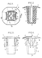
- FIG. 1 shows a cage-nut established according to the invention in cross section according to I-I, FIG. 3.
- Figures 2, 3 and 4 show the same cage-nut, respectively in axial section along II-II, Figure 1, in side view along arrow III, Figure 1, and in side view along arrow IV, Figure 1 .
- the nut cage considered 1 has the general shape of a sealed cup of symmetrical shape with respect to a central axis X and composed by a bottom 2 successively connected to a side wall 3 and to a radial flange 4.
- the side wall 3 whose outer contour is square or at least writable in a square, comprises two portions each extending over half of the total length of the cage considered along its axis X, namely a portion 5 in trunk of pyramid slightly converging towards the bottom 2 and a prismatic portion 6 extending the large base of the portion 5.
- the four faces making up the pyramidal portion 5 are identical.
- the prismatic portion 6 has, in cross section, the general shape of a rectangle in the sense that two of the faces 6 portion of this portion are relatively narrow and spaced from one another while the other two faces 62 are relatively wide and close together, the adjacent pyramidal portion 5 being connected externally to these latter faces 62 by re-entrant transverse projections 7.
- Each of the two faces 62 comprises an outer central longitudinal rib 8 which is extended by two triangular wings 9 whose planes form between them a widely open V, for example of the order of 120 to 150 °.
- the wings 9 can be folded elastically against the corresponding 62 faces and their thickness is such that, when they are folded against these faces, they are inscribed in the square defined by the other two faces 61.
- each wing extends along a right triangle which is connected to the rib 8 along one side a of the right angle forming a hinge, the other side b of the right angle extending transversely, that is to say perpendicular to the axis X, at an axial distance, from the edge of the flange 4, substantially equal to the thickness of the fixing sheet 10 (see FIG. 4).
- hypotenuse c of the right triangle considered as an oblique sliding ramp shape, capable of cooperating, during assembly of the cage, with the opposite edge of the square hole T (FIG. 1) into which this cage is introduced.
- each triangle opposite the longitudinal hinge side a , is advantageously chipped along a straight section d parallel to said side a .
- each triangular wing opposite its transverse side b , is arranged on the side of the bottom 2 of the cage.
- the collar 4 is advantageously constituted by a thin, slightly convex veil covering the cage in the manner of an umbrella, the edge of this collar being able to come to bear elastically in leaktight manner against the sheet 10 at the end of the assembly of the cage .
- the interior volume of the cage is lined with longitudinal ribs 11 molded from this cage and projecting radially on the four faces of the latter so as to reserve axially in the center of the cage a narrower space than the screws to be received. .
- these screws can hollow out their threads in the material constituting said ribs, which is a plastic material such as in particular a polyamide or an acetal resin.
- the square holes T drilled in the sheet 10 to receive the cages considered have dimensions which are only very little greater than those of the square contour of the prismatic portion 6 of each cage.
- the dimensions of the cage are such that, at this instant, the wings 9 have completely passed through the sheet and relax transversely behind this sheet while firmly pressing against the face of said sheet, inaccessible from the outside.
Landscapes
- Engineering & Computer Science (AREA)
- General Engineering & Computer Science (AREA)
- Mechanical Engineering (AREA)
- Dowels (AREA)
- Connection Of Plates (AREA)
- Buffer Packaging (AREA)
- Tents Or Canopies (AREA)
Description
L'invention est relative aux cages-écrous en matière plastique rendant possibles des fixations de type aveugle par vissage, c'est-à-dire agencées de façon à pouvoir être posées et fixées sur une tôle à partir de l'une des faces de cette tôle en vue de recevoir une vis se présentant du côté de cette même face, en raison de l'inaccessibilité de l'autre face due par exemple au fait que la tôle fait partie d'un caisson fermé au moins partiellement, comme il arrive fréquemment pour les carrosseries de véhicules.The invention relates to plastic nut cages making blind type screw fastenings possible, that is to say arranged so that they can be laid and fixed on a sheet metal from one of the faces of this sheet for receiving a screw on the side of the same side, due to the inaccessibility of the other side due for example to the fact that the sheet is part of a box closed at least partially, as it happens frequently for vehicle bodies.
Elle concerne plus particulièrement, parmi ces cages-écrous, celles qui sont susceptibles de coagir avec un trou carré percé dans la tôle de fixation et qui présentent la forme générale d'un godet étanche comprenant un fond raccordé successivement à une paroi latérale et à une collerette radiale, la paroi latérale présentant un contour extérieur carré et étant épaissie par au moins des nervures intérieures ne dégageant axialement qu'un passage plus étroit que les vis de fixation.It relates more particularly, among these nut cages, those which are capable of interacting with a square hole drilled in the fixing plate and which have the general shape of a sealed cup comprising a bottom successively connected to a side wall and to a radial flange, the side wall having a square external contour and being thickened by at least internal ribs axially freeing only a narrower passage than the fixing screws.
La mise en oeuvre d'une telle cage est la suivante.The implementation of such a cage is as follows.
On introduit la cage dans un trou carré de la tôle de fixation avec son fond en premier et jusqu'à application de sa collerette contre le bord du trou.The cage is introduced into a square hole in the fixing sheet with its bottom first and until its flange is applied against the edge of the hole.
Pour monter une pièce quelconque sur la tôle, il suffit alors de faire traverser un trou de cette pièce par une vis appropriée, puis de visser à fond cette vis dans la cage ainsi mise en place.To mount any part on the sheet, it suffices to pass a hole in this part through an appropriate screw, then to screw this screw fully into the cage thus put in place.
Ladite vis creuse alors son filet dans la matière plastique de la cage et la légère expansion radiale qui en résulte de la cage bloque irréversiblement sur la tôle cette cage ainsi que la vis et que la pièce traversée par cette vis.Said screw then digs its thread into the plastic of the cage and the slight radial expansion which results from the cage irreversibly blocks on the sheet metal this cage as well as the screw and that the part crossed by this screw.
Dans les modes de réalisation connus des cages en question (voir le document US-A- 4 077 300) les quatre faces composant la paroi latérale de la cage sont identiques et l'immobilisation de la cage sur la tôle à la fin de sa course de mise en place est assurée par friction mutelle de ses faces contre les bords du trou carré, les dimensions de la cage étant choisies en fonction de celles du trou de façon qu'il n'y ait alors aucun jeu entre la cage et le trou.In the known embodiments of the cages in question (see document US-A-4,077,300) the four faces making up the side wall of the cage are identical and the immobilization of the cage on the sheet at the end of its stroke positioning is ensured by mutual friction of its faces against the edges of the square hole, the dimensions of the cage being chosen as a function of those of the hole so that there is then no play between the cage and the hole .
L'irréversibilité du montage peut être renforcée par accrochage de la face inaccessible de la tôle, au niveau du bord du trou, sur de légères surépaisseurs de matière prévues sur les zones centrales des quatre faces de la cage, juste en deçà de leurs plages planes qui sont entourées par la tôle en fin de montage, le franchissement de ces surépaisseurs lors du montage exigeant de légères déformations radiales des faces considérées.The irreversibility of the assembly can be reinforced by hooking the inaccessible face of the sheet, at the level of the edge of the hole, on slight thicknesses of material provided on the central areas of the four sides of the cage, just below their flat ranges. which are surrounded by the sheet at the end of assembly, the crossing of these extra thicknesses during assembly requiring slight radial deformations of the faces considered.
Mais ces surépaisseurs ont une très faible hauteur, de l'ordre de 0,2 mm, vu la faible déformabi- lité des faces considérées.However, these extra thicknesses have a very low height, of the order of 0.2 mm, given the low deformability of the faces considered.
Il en résulte que l'accrochage des cages sur la tôle, tant avant qu'après vissage des vis correspondantes, est peu solide.It follows that the attachment of the cages on the sheet, both before and after screwing the corresponding screws, is not very solid.
L'invention a pour but, surtout, d'augmenter la solidité de cet accrochage tout en facilitant le montage.The invention aims, above all, to increase the solidity of this attachment while facilitating assembly.
A cet effet, les cages-écrous selon l'invention sont essentiellement caractérisées en ce que deux de leurs faces latérales opposées comprennent chacune, venues de moulage avec elle, deux ailes présentant chacune la forme générale d'un triangle rectangle et raccordées à la zone centrale longitudinale de la face correspondante le long d'un côté de l'angle droit du triangle formant charnière de flexion, l'autre côté de l'angle droit s'étendant transversalement et étant propre à prendre appui contre la tôle en fin de montage et l'hypoténuse servant de rampe de glissement contre un bord de trou carré de fixation lors du montage de la cage sur la tôle perforée par ce trou, le contour général extérieur de la portion ailetée de la cage étant carré uniquement lorsque les ailes sont rabattues élastiquement contre les faces correspondantes de cette cage.To this end, the nut cages according to the invention are essentially characterized in that two of their opposite lateral faces each comprise, coming from molding with it, two wings each having the general shape of a right triangle and connected to the zone longitudinal center of the corresponding face along one side of the right angle of the triangle forming a bending hinge, the other side of the right angle extending transversely and being able to bear against the sheet at the end of mounting and the hypotenuse serving as a sliding ramp against an edge of square fixing hole when mounting the cage on the sheet perforated by this hole, the general external contour of the finned portion of the cage being square only when the wings are folded elastically against the corresponding faces of this cage.
Dans des modes de réalisation préférés, on a recours en outre à l'une et/ou l'autre des dispositions suivantes :
- l'angle, de chaque aile, le plus éloigné du corps de la cage est écorné selon un segment de droite parallèle à la direction longitudinale de la cage,
- la section transversale de la paroi latérale continue de la cage, au niveau de sa portion ailetée, est rectangulaire, les deux faces qui portent les ailes étant plus grandes et plus rapprochées mutuellement que les deux autres.
- the angle, of each wing, the furthest from the body of the cage is chipped along a line segment parallel to the longitudinal direction of the cage,
- the cross section of the continuous side wall of the cage, at its finned portion, is rectangular, the two faces which carry the wings being larger and closer together than the other two.
L'invention comprend, mises à part ces dispositions principales, certaines autres dispositions qui s'utilisent de préférence en même temps et dont il sera plus explicitement question ci-après.The invention includes, apart from these main provisions, certain other provisions which are preferably used at the same time and which will be more explicitly discussed below.
Dans ce qui suit, l'on va décrire un mode de réalisation préféré de l'invention en se référant au dessin ci-annexé d'une manière bien entendu non limitative.In what follows, a preferred embodiment of the invention will be described with reference to the attached drawing, of course in a non-limiting manner.
La figure 1, de ce dessin, montre une cage-écrou établie selon l'invention en coupe transversale selon I-I, figure 3.FIG. 1, of this drawing, shows a cage-nut established according to the invention in cross section according to I-I, FIG. 3.
Les figures 2, 3 et 4 montrent la même cage-écrou, respectivement en coupe axiale selon II-II, figure 1, en vue de côté selon la flèche III, figure 1, et en vue de côté suivant la flèche IV, figure 1.Figures 2, 3 and 4 show the same cage-nut, respectively in axial section along II-II, Figure 1, in side view along arrow III, Figure 1, and in side view along arrow IV, Figure 1 .
D'une façon connue en soi, la cage écrou considérée 1 présente la forme générale d'un godet étanche de forme symétrique par rapport à un axe central X et composé par un fond 2 raccordé successivement à une paroi latérale 3 et à une collerette radiale 4.In a manner known per se, the nut cage considered 1 has the general shape of a sealed cup of symmetrical shape with respect to a central axis X and composed by a bottom 2 successively connected to a side wall 3 and to a
La paroi latérale 3, dont le contour extérieur est carré ou tout au moins inscriptible dans un carré, comprend deux portions s'étendant chacune sur la moitié de la longueur totale de la cage considérée selon son axe X, savoir une portion 5 en tronc de pyramide légèrement convergente vers le fond 2 et une portion prismatique 6 prolongeant la grande base de la portion 5.The side wall 3, whose outer contour is square or at least writable in a square, comprises two portions each extending over half of the total length of the cage considered along its axis X, namely a
Les quatre faces composant la portion pyramidale 5 sont identiques.The four faces making up the
Mais la portion prismatique 6 présente en section transversale la forme générale d'un rectangle en ce sens que deux des faces 6₁ de cette portion sont relativement étroites et écartées l'une de l'autre alors que les deux autres faces 6₂ sont relativement larges et rapprochées, la portion pyramidale 5 adjacente étant raccordée extérieurement à ces dernières faces 6₂ par des ressauts transversaux rentrants 7.However, the
Chacune des deux faces 6₂ comprend une nervure longitudinale centrale extérieure 8 qui est prolongée par deux ailes triangulaires 9 dont les plans forment entre eux un V largement ouvert, par exemple de l'ordre de 120 à 150°.Each of the two
Les ailes 9 peuvent être rabattues élastiquement contre les faces 6₂ correspondantes et leur épaisseur est telle que, lorsqu'elles sont rabattues contre ces faces, elles sont inscrites dans le carré défini par les deux autres faces 6₁.The
Le contour de chaque aile s'étend selon un triangle rectangle qui est raccordé à la nervure 8 selon un côté a de l'angle droit formant charnière, l'autre côté b de l'angle droit s'étendant transversalement, c'est-à-dire perpendiculairement à l'axe X, à une distance axiale, du bord de la collerette 4, sensiblement égale à l'épaisseur de la tôle de fixation 10 (voir figure 4).The contour of each wing extends along a right triangle which is connected to the rib 8 along one side a of the right angle forming a hinge, the other side b of the right angle extending transversely, that is to say perpendicular to the axis X, at an axial distance, from the edge of the
L'hypoténuse c du triangle rectangle considéré forme rampe de glissement oblique, propre à coopérer, lors du montage de la cage, avec le bord en regard du trou carré T (figure 1) dans lequel est introduite cette cage.The hypotenuse c of the right triangle considered as an oblique sliding ramp shape, capable of cooperating, during assembly of the cage, with the opposite edge of the square hole T (FIG. 1) into which this cage is introduced.
L'angle, de chaque triangle, opposé au côté-charnière longitudinal a, est avantageusement écorné selon un tronçon rectiligne d parallèle audit côté a.The angle of each triangle, opposite the longitudinal hinge side a , is advantageously chipped along a straight section d parallel to said side a .
La pointe P, de chaque aile triangulaire, opposée à son côté transversal b, est disposée du côté du fond 2 de la cage.The point P, of each triangular wing, opposite its transverse side b , is arranged on the side of the bottom 2 of the cage.
La collerette 4 est avantageusement constituée par un voile mince légèrement bombé recouvrant la cage à la façon d'une ombrelle, le bord de cette collerette étant propre à venir prendre appui élastiquement de façon étanche contre la tôle 10 à la fin du montage de la cage.The
Le volume intérieur de la cage est tapissé par des nervures longitudinales 11 venues de moulage avec cette cage et faisant saillie radialement sur les quatre faces de celle-ci de façon à réserver axialement au centre de la cage un espace plus étroit que les vis à recevoir.The interior volume of the cage is lined with
De la sorte, ces vis peuvent creuser leurs filets dans la matière constitutive desdites nervures, qui est une matière plastique telle que notamment une polyamide ou une résine acétal.In this way, these screws can hollow out their threads in the material constituting said ribs, which is a plastic material such as in particular a polyamide or an acetal resin.
Les trous carrés T percés dans la tôle 10 pour recevoir les cages considérées présentent des dimensions qui sont seulement très peu supérieures à celles du contour carré de la portion prismatique 6 de chaque cage.The square holes T drilled in the
Pour effectuer le montage d'une cage dans un tel trou T, il suffit d'introduire la cage dans ce trou, parallèlement à son axe X, avec le fond 2 en avant.To mount a cage in such a hole T, it suffices to introduce the cage into this hole, parallel to its axis X, with the bottom 2 in front.
Lorsque les ailes 9 viennent au contact avec les bords du trou en commençant par leurs pointes P, leurs tranches obliques c glissent le long de ces bords : ces ailes fléchissent donc progressivement de façon à s'escamoter suffisamment pour le passage de la cage, et ce jusqu'à ce que la collerette 4 vienne buter contre la tôle 10.When the
Les cotes de la cage sont telles qu'à cet instant les ailes 9 ont totalement traversé la tôle et se détendent transversalement derrière cette tôle en prenant solidement appui contre la face, de ladite tôle, inaccessible de l'extérieur.The dimensions of the cage are such that, at this instant, the
Les portions S (figure 1) de ces ailes qui sont alors transversalement en saillie au-delà du carré délimitant le trou T prennent alors appui axialement contre la tôle en assurant un accrochage solide et irréversible de la cage sur cette tôle.The portions S (FIG. 1) of these wings which are then transversely projecting beyond the square delimiting the hole T then bear axially against the sheet, ensuring a solid and irreversible attachment of the cage to this sheet.
En suite de quoi et quel que soit le mode de réalisation adopté, on dispose finalement d'une cage-écrou dont la constitution, le montage et les avantages résultent suffisamment de ce qui précède.Following what and whatever the embodiment adopted, there is finally a cage-nut whose constitution, mounting and advantages result sufficiently from the above.
Comme il va de soi, et comme il résulte d'ailleurs déjà de ce qui précède, l'invention ne se limite nullement à ceux de ses modes d'application et de réalisation qui ont été plus spécialement envisagés ; elle en embrasse, au contraire, toutes les variantes.As is obvious, and as already follows from the foregoing, the invention is in no way limited to those of its modes of application and embodiments which have been more especially envisaged; on the contrary, it embraces all its variants.
Claims (3)
- A screw grommet of plastic material for a blind fixing, adapted to be fitted in a square hole (T) in a plate (10) and receive a screw tapping its thread therein, and having the general shape of a sealed cup or bucket comprising a base (2) connected successively to four side surfaces and to a radial collar (4), characterised in that two of its opposite side surfaces (6₂) each comprise integrally therewith two flanges (9) each having the general shape of a right-angled triangle and connected to the central longitudinal zone of the corresponding face along a side (a) of the right-angle of the triangle forming a flexural hinge, the other side (b) of the right angle extending transversely and being adapted to bear against the plate (10) at the end of fitting and the hypotenuse (c) acting as a slideway against an edge of the square fixing hole (T) during the fitting of the grommet on the plate, the general external contour of the flanged portion of the grommet being square only when the flanges are folded elastically against the corresponding faces of said grommet.
- A screw grommet according to claim 1, characterised in that the angle of each flange furthest away from the body of the grommet is chamfered along a segment of a straight line (d) parallel to the longitudinal direction of the grommet.
- A screw grommet according to any one of the preceding claims, characterised in that the cross-section of the continuous side wall of the grommet at its flanged portion is rectangular, the two faces (6₂) which bear the flanges being larger and closer together than the other two (6₁).
Applications Claiming Priority (2)
| Application Number | Priority Date | Filing Date | Title |
|---|---|---|---|
| FR9001404 | 1990-02-07 | ||
| FR9001404A FR2657926B1 (en) | 1990-02-07 | 1990-02-07 | IMPROVEMENTS ON NUT CAGES FOR BLIND TYPE FASTENERS. |
Publications (2)
| Publication Number | Publication Date |
|---|---|
| EP0441691A1 EP0441691A1 (en) | 1991-08-14 |
| EP0441691B1 true EP0441691B1 (en) | 1993-10-13 |
Family
ID=9393460
Family Applications (1)
| Application Number | Title | Priority Date | Filing Date |
|---|---|---|---|
| EP19910400258 Expired - Lifetime EP0441691B1 (en) | 1990-02-07 | 1991-02-04 | Nut cages for blind fastening |
Country Status (4)
| Country | Link |
|---|---|
| EP (1) | EP0441691B1 (en) |
| DE (1) | DE69100485T2 (en) |
| ES (1) | ES2046019T3 (en) |
| FR (1) | FR2657926B1 (en) |
Families Citing this family (8)
| Publication number | Priority date | Publication date | Assignee | Title |
|---|---|---|---|---|
| DE9314824U1 (en) * | 1993-09-29 | 1993-11-25 | Trw United-Carr Gmbh & Co Kg, 67677 Enkenbach-Alsenborn | Screw connection |
| DE19930728B4 (en) | 1999-07-05 | 2005-12-01 | Itw-Ateco Gmbh | Anchor for fixing an object to a carrier made of flat material |
| DE10306538B4 (en) * | 2003-02-15 | 2005-04-28 | Itw Automotive Prod Gmbh & Co | Expanding nut |
| US20060083601A1 (en) * | 2004-10-20 | 2006-04-20 | Moerke Benjamin H | Grommet |
| DE202005005009U1 (en) * | 2005-03-24 | 2005-07-28 | Zeglaplast Formenbau | Component fastening unit for use on e.g. steel sheet, has annular sealing unit designed as single-piece with fastening unit head, and fastening unit shank with deformation section that interacts with sealing unit |
| DE202005017435U1 (en) * | 2005-11-08 | 2006-03-16 | Berner Gmbh | Dowels, in particular for solid building materials |
| DE202005019958U1 (en) * | 2005-12-21 | 2007-04-26 | Fischerwerke Artur Fischer Gmbh & Co. Kg | mounting assembly |
| DE102021118921A1 (en) | 2020-08-04 | 2022-02-10 | Illinois Tool Works Inc. | Assembly sleeve |
Family Cites Families (5)
| Publication number | Priority date | Publication date | Assignee | Title |
|---|---|---|---|---|
| JPS5422839Y2 (en) * | 1971-11-11 | 1979-08-08 | ||
| US4077300A (en) * | 1973-09-10 | 1978-03-07 | Nifco Inc. | Plastic screw grommet |
| FR2375480A1 (en) * | 1976-12-21 | 1978-07-21 | Comet | IMPROVEMENTS TO FIXING DEVICES |
| DE2814969A1 (en) * | 1978-04-06 | 1979-10-11 | Springfix Befestigungstechnik | Moulded insert for mounting in sheet metal - has cylindrical body located in sheet aperture by flanged head and tapered ribs |
| US4521148A (en) * | 1983-05-06 | 1985-06-04 | Nifco Inc. | Hinged mirror image plastic fastener for quick assembly to threaded male members |
-
1990
- 1990-02-07 FR FR9001404A patent/FR2657926B1/en not_active Expired - Lifetime
-
1991
- 1991-02-04 DE DE1991600485 patent/DE69100485T2/en not_active Expired - Fee Related
- 1991-02-04 ES ES91400258T patent/ES2046019T3/en not_active Expired - Lifetime
- 1991-02-04 EP EP19910400258 patent/EP0441691B1/en not_active Expired - Lifetime
Also Published As
| Publication number | Publication date |
|---|---|
| DE69100485T2 (en) | 1994-04-21 |
| DE69100485D1 (en) | 1993-11-18 |
| FR2657926B1 (en) | 1992-05-29 |
| EP0441691A1 (en) | 1991-08-14 |
| FR2657926A1 (en) | 1991-08-09 |
| ES2046019T3 (en) | 1994-01-16 |
Similar Documents
| Publication | Publication Date | Title |
|---|---|---|
| EP0053543B1 (en) | Devices for fixing objects to sheet metals accessible from one side only | |
| EP0311498B1 (en) | Fastening systems having nuts secured within cages | |
| EP1444402A1 (en) | Channel element for road drainage gutter | |
| EP1722453B1 (en) | Flush mounted box | |
| EP0441691B1 (en) | Nut cages for blind fastening | |
| EP1072502B1 (en) | Shearable gliding fastening for a plastic element on a support | |
| CA2200677C (en) | Assembly system for prefabricated panels to create a pool bulkhead and the pool bulkhead thus obtained | |
| FR2766905A1 (en) | Folded section girder for building construction | |
| FR2585786A1 (en) | ATTACHED FASTENER AND ATTACHMENT ASSEMBLY | |
| EP0143055B1 (en) | Supporting structure for establishing a rim rafter for a roof truss | |
| EP0609152A1 (en) | Motor vehicle roof rack bar | |
| FR2702808A1 (en) | Improvements to devices for fastening objects onto sheets which are accessible from just one side | |
| FR2790520A1 (en) | Fixings for attaching grid on road gutter comprises clip and component deforming clip by compression followed by going back to original shape to ensure assembly | |
| EP0908991B1 (en) | Electrical cabling duct accessory | |
| FR2766904A1 (en) | C- sectional steel girder for building | |
| WO2000031846A1 (en) | Gland with sealing lining and thick clamping teeth | |
| EP2431641B1 (en) | Fixing device of a connection piece of a fluid carrying pipe to a hollow wall | |
| EP0978660B1 (en) | Fastening device, consisting of a clamping device and of a fastening rod, for joining two parts to one another | |
| FR2473806A1 (en) | Small electric motor for vehicle windscreen wipers - has gear casing fitted to motor casing with bearing plate providing seat for roller bearing | |
| FR2820554A1 (en) | COMPOSABLE CHUTE | |
| FR2757224A1 (en) | Frame for barrier fence | |
| FR2804153A1 (en) | Hinge for door leaf has blade and blade and counter blade with lugs on one extending through holes in door to be received in other | |
| FR2762367A1 (en) | Turn lock threaded fastener for motor vehicle bodywork | |
| FR3140409A1 (en) | Fixing device | |
| FR3123675A1 (en) | method and device for retrofitting an aluminum cover on an existing door and window frame. |
Legal Events
| Date | Code | Title | Description |
|---|---|---|---|
| PUAI | Public reference made under article 153(3) epc to a published international application that has entered the european phase |
Free format text: ORIGINAL CODE: 0009012 |
|
| AK | Designated contracting states |
Kind code of ref document: A1 Designated state(s): BE DE ES GB IT |
|
| 17P | Request for examination filed |
Effective date: 19911008 |
|
| 17Q | First examination report despatched |
Effective date: 19920612 |
|
| GRAA | (expected) grant |
Free format text: ORIGINAL CODE: 0009210 |
|
| AK | Designated contracting states |
Kind code of ref document: B1 Designated state(s): BE DE ES GB IT |
|
| REF | Corresponds to: |
Ref document number: 69100485 Country of ref document: DE Date of ref document: 19931118 |
|
| GBT | Gb: translation of ep patent filed (gb section 77(6)(a)/1977) |
Effective date: 19931026 |
|
| ITF | It: translation for a ep patent filed | ||
| REG | Reference to a national code |
Ref country code: ES Ref legal event code: FG2A Ref document number: 2046019 Country of ref document: ES Kind code of ref document: T3 |
|
| PLBE | No opposition filed within time limit |
Free format text: ORIGINAL CODE: 0009261 |
|
| STAA | Information on the status of an ep patent application or granted ep patent |
Free format text: STATUS: NO OPPOSITION FILED WITHIN TIME LIMIT |
|
| 26N | No opposition filed | ||
| PGFP | Annual fee paid to national office [announced via postgrant information from national office to epo] |
Ref country code: BE Payment date: 19971201 Year of fee payment: 8 |
|
| PGFP | Annual fee paid to national office [announced via postgrant information from national office to epo] |
Ref country code: GB Payment date: 19980126 Year of fee payment: 8 |
|
| PG25 | Lapsed in a contracting state [announced via postgrant information from national office to epo] |
Ref country code: GB Free format text: LAPSE BECAUSE OF NON-PAYMENT OF DUE FEES Effective date: 19990204 |
|
| PG25 | Lapsed in a contracting state [announced via postgrant information from national office to epo] |
Ref country code: BE Free format text: LAPSE BECAUSE OF NON-PAYMENT OF DUE FEES Effective date: 19990228 |
|
| BERE | Be: lapsed |
Owner name: COMET Effective date: 19990228 |
|
| GBPC | Gb: european patent ceased through non-payment of renewal fee |
Effective date: 19990204 |
|
| PG25 | Lapsed in a contracting state [announced via postgrant information from national office to epo] |
Ref country code: IT Free format text: LAPSE BECAUSE OF NON-PAYMENT OF DUE FEES;WARNING: LAPSES OF ITALIAN PATENTS WITH EFFECTIVE DATE BEFORE 2007 MAY HAVE OCCURRED AT ANY TIME BEFORE 2007. THE CORRECT EFFECTIVE DATE MAY BE DIFFERENT FROM THE ONE RECORDED. Effective date: 20050204 |
|
| PGFP | Annual fee paid to national office [announced via postgrant information from national office to epo] |
Ref country code: ES Payment date: 20090226 Year of fee payment: 19 |
|
| PGFP | Annual fee paid to national office [announced via postgrant information from national office to epo] |
Ref country code: DE Payment date: 20090331 Year of fee payment: 19 |
|
| PG25 | Lapsed in a contracting state [announced via postgrant information from national office to epo] |
Ref country code: DE Free format text: LAPSE BECAUSE OF NON-PAYMENT OF DUE FEES Effective date: 20100901 |
|
| REG | Reference to a national code |
Ref country code: ES Ref legal event code: FD2A Effective date: 20110301 |
|
| PG25 | Lapsed in a contracting state [announced via postgrant information from national office to epo] |
Ref country code: ES Free format text: LAPSE BECAUSE OF NON-PAYMENT OF DUE FEES Effective date: 20110205 |