EP0441466A2 - Double-walled hollow body having intermediate layer and method of manufacturing the same - Google Patents
Double-walled hollow body having intermediate layer and method of manufacturing the same Download PDFInfo
- Publication number
- EP0441466A2 EP0441466A2 EP91250031A EP91250031A EP0441466A2 EP 0441466 A2 EP0441466 A2 EP 0441466A2 EP 91250031 A EP91250031 A EP 91250031A EP 91250031 A EP91250031 A EP 91250031A EP 0441466 A2 EP0441466 A2 EP 0441466A2
- Authority
- EP
- European Patent Office
- Prior art keywords
- hollow body
- intermediate layer
- double
- inner hollow
- wall
- Prior art date
- Legal status (The legal status is an assumption and is not a legal conclusion. Google has not performed a legal analysis and makes no representation as to the accuracy of the status listed.)
- Withdrawn
Links
Images
Classifications
-
- F—MECHANICAL ENGINEERING; LIGHTING; HEATING; WEAPONS; BLASTING
- F01—MACHINES OR ENGINES IN GENERAL; ENGINE PLANTS IN GENERAL; STEAM ENGINES
- F01N—GAS-FLOW SILENCERS OR EXHAUST APPARATUS FOR MACHINES OR ENGINES IN GENERAL; GAS-FLOW SILENCERS OR EXHAUST APPARATUS FOR INTERNAL COMBUSTION ENGINES
- F01N13/00—Exhaust or silencing apparatus characterised by constructional features ; Exhaust or silencing apparatus, or parts thereof, having pertinent characteristics not provided for in, or of interest apart from, groups F01N1/00 - F01N5/00, F01N9/00, F01N11/00
- F01N13/18—Construction facilitating manufacture, assembly, or disassembly
- F01N13/1883—Construction facilitating manufacture, assembly, or disassembly manufactured by hydroforming
-
- F—MECHANICAL ENGINEERING; LIGHTING; HEATING; WEAPONS; BLASTING
- F01—MACHINES OR ENGINES IN GENERAL; ENGINE PLANTS IN GENERAL; STEAM ENGINES
- F01N—GAS-FLOW SILENCERS OR EXHAUST APPARATUS FOR MACHINES OR ENGINES IN GENERAL; GAS-FLOW SILENCERS OR EXHAUST APPARATUS FOR INTERNAL COMBUSTION ENGINES
- F01N13/00—Exhaust or silencing apparatus characterised by constructional features ; Exhaust or silencing apparatus, or parts thereof, having pertinent characteristics not provided for in, or of interest apart from, groups F01N1/00 - F01N5/00, F01N9/00, F01N11/00
- F01N13/14—Exhaust or silencing apparatus characterised by constructional features ; Exhaust or silencing apparatus, or parts thereof, having pertinent characteristics not provided for in, or of interest apart from, groups F01N1/00 - F01N5/00, F01N9/00, F01N11/00 having thermal insulation
- F01N13/141—Double-walled exhaust pipes or housings
-
- F—MECHANICAL ENGINEERING; LIGHTING; HEATING; WEAPONS; BLASTING
- F01—MACHINES OR ENGINES IN GENERAL; ENGINE PLANTS IN GENERAL; STEAM ENGINES
- F01N—GAS-FLOW SILENCERS OR EXHAUST APPARATUS FOR MACHINES OR ENGINES IN GENERAL; GAS-FLOW SILENCERS OR EXHAUST APPARATUS FOR INTERNAL COMBUSTION ENGINES
- F01N13/00—Exhaust or silencing apparatus characterised by constructional features ; Exhaust or silencing apparatus, or parts thereof, having pertinent characteristics not provided for in, or of interest apart from, groups F01N1/00 - F01N5/00, F01N9/00, F01N11/00
- F01N13/16—Selection of particular materials
-
- F—MECHANICAL ENGINEERING; LIGHTING; HEATING; WEAPONS; BLASTING
- F16—ENGINEERING ELEMENTS AND UNITS; GENERAL MEASURES FOR PRODUCING AND MAINTAINING EFFECTIVE FUNCTIONING OF MACHINES OR INSTALLATIONS; THERMAL INSULATION IN GENERAL
- F16L—PIPES; JOINTS OR FITTINGS FOR PIPES; SUPPORTS FOR PIPES, CABLES OR PROTECTIVE TUBING; MEANS FOR THERMAL INSULATION IN GENERAL
- F16L59/00—Thermal insulation in general
- F16L59/02—Shape or form of insulating materials, with or without coverings integral with the insulating materials
- F16L59/029—Shape or form of insulating materials, with or without coverings integral with the insulating materials layered
-
- F—MECHANICAL ENGINEERING; LIGHTING; HEATING; WEAPONS; BLASTING
- F01—MACHINES OR ENGINES IN GENERAL; ENGINE PLANTS IN GENERAL; STEAM ENGINES
- F01N—GAS-FLOW SILENCERS OR EXHAUST APPARATUS FOR MACHINES OR ENGINES IN GENERAL; GAS-FLOW SILENCERS OR EXHAUST APPARATUS FOR INTERNAL COMBUSTION ENGINES
- F01N13/00—Exhaust or silencing apparatus characterised by constructional features ; Exhaust or silencing apparatus, or parts thereof, having pertinent characteristics not provided for in, or of interest apart from, groups F01N1/00 - F01N5/00, F01N9/00, F01N11/00
- F01N13/08—Other arrangements or adaptations of exhaust conduits
-
- F—MECHANICAL ENGINEERING; LIGHTING; HEATING; WEAPONS; BLASTING
- F01—MACHINES OR ENGINES IN GENERAL; ENGINE PLANTS IN GENERAL; STEAM ENGINES
- F01N—GAS-FLOW SILENCERS OR EXHAUST APPARATUS FOR MACHINES OR ENGINES IN GENERAL; GAS-FLOW SILENCERS OR EXHAUST APPARATUS FOR INTERNAL COMBUSTION ENGINES
- F01N2310/00—Selection of sound absorbing or insulating material
Definitions
- the invention relates to a double-walled hollow body according to the preamble of claim 1 and a method for producing the same.
- a generic double wall hollow body is known from DE-PS 37 12 193. It consists of an inner tube and an outer tube, which are arranged at a distance so that they form an annular space in which ceramic powder is arranged in the sense of sound insulation.
- the outer tube consists of a less temperature-resistant steel and is connected to the inner tube in a gastight manner at its retracted ends.
- a disadvantage of this proposal is the required filling technique of the ceramic powder, which is an obstacle to the mass production of large quantities.
- the proposed double wall tube is also not suitable as a construction element for the transmission of forces and torques.
- German Offenlegungsschrift 23 55 126 which also has an inner pipe and an outer pipe with an insulating layer in between.
- the insulating material preferably consists of aluminum silicate ceramic. This double wall pipe is also not suitable for transmitting larger forces or torques.
- the object of the invention is to provide an improved double-walled hollow body which is suitable as a sound-absorbing structural element in motor vehicle construction for mass production and can transmit greater forces or torques.
- the double-wall hollow body according to the invention is characterized in that the interlayer made of the non-metallic, sound-absorbing material separates the inner from the outer hollow body over the entire circumference by a force-locking connection of the inner with the outer hollow body.
- the cross-sectional profile of the inner or outer hollow body can be arbitrary and is primarily dependent on the respective intended use of such a double-wall hollow body.
- the cross section is preferably circular, since the production of such hollow bodies is inexpensive and the production of a double wall tube is particularly simple.
- the double-walled hollow body according to the invention has the advantage that the elimination of the weld seam passing through the intermediate layer gives more freedom in the selection of the best possible insulating material, since there is no need to consider welding compatibility.
- the non-positive connection forms a continuous long section, which is not interrupted by a metallic bridge and thus the sound insulation is particularly effective.
- the intermediate layer is first applied to the inner hollow body and then this is inserted into the outer hollow body and finally at least one of the two hollow bodies is plastically deformed to such an extent that it non-positively engages with the other hollow body is coming.
- the type of application of the intermediate layer to the inner hollow body can take place in various ways. One of the possibilities is to pull the intermediate layer in the form of a tube onto the inner hollow body. The use of a flat product for the intermediate layer and the wrapping of the inner hollow body in the intermediate layer pre-cut to size is more cost-effective. Depending on the type of insulation, it can be connected to the inner hollow body using heat or an adhesive.
- the expansion required after inserting the inner hollow body provided with the intermediate layer into the outer hollow body having a larger internal dimension can be hydraulic or mechanical, Z. B. by pushing through a widening inner tool, an additional widening being required in the region of the liner-free section. Hydraulic expansion is always preferable if more than one section is to be free of intermediate layers or if this section is not at the end of the hollow body.
- Another possibility of applying the intermediate layer consists in winding a band of the insulating material onto the inner hollow body, be it in one or more layers.
- a readily plastically deformable material is chosen as the material for the inner or outer hollow body, both hollow bodies being made of the same material for cost reasons.
- the intermediate layer used should be inexpensive and particularly suitable with regard to the application to the inner hollow body and have a good sound insulation value. These conditions are e.g. B. met to a high degree by a bitumen film.
- the method described is advantageously used to produce a sound-insulated propeller shaft which has an intermediate layer-free section at each end.
- the cardan shaft is one of the elements that emit a large sound spectrum.
- the proposed double wall tube is therefore particularly suitable for remedying this without the function of the cardan shaft having to be restricted in any way.
- the double wall tube has the advantage of saving weight compared to the previously known forging.
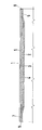
- an embodiment of the double-wall hollow body according to the invention in the form of a double-wall pipe 1 is shown in cross-section. It consists of an inner tube 2, for. B. of steel St. 37, which is coated with a non-metallic, sound-absorbing intermediate layer 3.
- the intermediate layer 3 should consist of bitumen film and have a thickness of, for example, 1 mm.
- the outer surface 4 of the inner tube 2 is provided with an adhesive and then the inner tube 2 has been rolled into the intermediate layer 3 cut to size beforehand.
- the resulting outer diameter of the coated inner tube 2 is, for. B. 1 - 3 mm less than the inner diameter of the outer tube 5 already produced, so that an easy insertion is possible.
- the dimensions of the tubes should be, for example, 2 (50 x 1) mm for the inner tube and 5 (55 x 1) mm for the outer tube.
- the outer tube 5 should also be a steel tube of the same material in this example. The open ends of the double-wall pipe 1 are then closed in a known manner and the inner pipe 2 is widened by a hydraulic method. The expansion process results in a non-positive connection of the inner tube 2 with the outer tube 5 including with the intermediate layer 3.
- the internal pressure can be determined such that only the inner tube 2 flows plastically and the outer tube 5 is not also formed.
- the length of the intermediate layer 3 applied to the inner tube 2 is dimensioned for the example of the cardan shaft in such a way that an intermediate layer-free section 6, 7 is formed at both ends.
- an intermediate layer-free section 6, 7 is formed at both ends.
- the corresponding connection piece also not shown here, can be welded on.
Landscapes
- Engineering & Computer Science (AREA)
- General Engineering & Computer Science (AREA)
- Mechanical Engineering (AREA)
- Chemical & Material Sciences (AREA)
- Combustion & Propulsion (AREA)
- Manufacturing & Machinery (AREA)
- Exhaust Silencers (AREA)
- Laminated Bodies (AREA)
- Shafts, Cranks, Connecting Bars, And Related Bearings (AREA)
Abstract
Description
Die Erfindung betrifft einen Doppelwandhohlkörper gemäß dem Gattungsbegriff des Anspruches 1 sowie ein Verfahren zur Herstellung desselben. Ein gattungsmäßiger Doppelwandhohlkörper ist aus der DE-PS 37 12 193 bekannt. Es besteht aus einem Innenrohr und einem Außenrohr, die mit Abstand so angeordnet sind, daß sie einen Ringraum bilden, in welchem Keramikpulver im Sinne eines Schallschutzes angeordnet ist. Das Außenrohr besteht gegenüber dem Innenrohr aus einem weniger temperaturfesten Stahl und ist an seinen eingezogenen Enden mit dem Innenrohr gasdicht verbunden. Nachteilig bei diesem Vorschlag ist die erforderliche Einfülltechnik des Keramikpulvers, die der Massenfertigung großer Stückzahlen hinderlich im Wege ist. Das vorgeschlagene Doppelwandrohr ist auch nicht geeignet als Konstruktionselement zur Übertragung von Kräften und Drehmomenten.The invention relates to a double-walled hollow body according to the preamble of claim 1 and a method for producing the same. A generic double wall hollow body is known from DE-PS 37 12 193. It consists of an inner tube and an outer tube, which are arranged at a distance so that they form an annular space in which ceramic powder is arranged in the sense of sound insulation. Compared to the inner tube, the outer tube consists of a less temperature-resistant steel and is connected to the inner tube in a gastight manner at its retracted ends. A disadvantage of this proposal is the required filling technique of the ceramic powder, which is an obstacle to the mass production of large quantities. The proposed double wall tube is also not suitable as a construction element for the transmission of forces and torques.
In der deutschen Offenlegungsschrift 23 55 126 ist ein Abgasrohr vorgeschlagen worden, das ebenfalls ein Innenrohr und ein Außenrohr mit einer dazwischenliegenden Isolierschicht aufweist. Vorzugsweise besteht das Isoliermaterial aus Aluminium-Silikat-Keramik. Auch dieses Doppelwandrohr ist nicht geeignet größere Kräfte oder Drehmomente zu übertragen.An exhaust pipe has been proposed in German Offenlegungsschrift 23 55 126, which also has an inner pipe and an outer pipe with an insulating layer in between. The insulating material preferably consists of aluminum silicate ceramic. This double wall pipe is also not suitable for transmitting larger forces or torques.
Aufgabe der Erfindung ist es, einen verbesserten Doppelwandhohlkörper anzugeben, der als schalldämmendes Konstruktionselement im Kraftfahrzeugbau für eine Massenfertigung geeignet ist und größere Kräfte bzw. Drehmomente übertragen kann.The object of the invention is to provide an improved double-walled hollow body which is suitable as a sound-absorbing structural element in motor vehicle construction for mass production and can transmit greater forces or torques.
Diese Aufgabe wird mit den im kennzeichnenden Teil des Anspruches 1 angegebenen Merkmalen gelöst. Vorteilhafte Weiterbildungen sind in den Unteransprüchen festgelegt, ebenso ein Verfahren zur Herstellung eines erfindungsgemäßen Doppelwandhohlkörpers.This object is achieved with the features specified in the characterizing part of claim 1. Advantageous further developments are defined in the subclaims, as is a method for producing a double-wall hollow body according to the invention.
Der erfindungsgemäße Doppelwandhohlkörper zeichnet sich dadurch aus, daß durch einen kraftschlüssigen Verbund des inneren mit dem äußeren Hohlkörper die Zwischenlage aus dem nichtmetallischen, schalldämmenden Werkstoff über den ganzen Umfang den inneren vom äußeren Hohlkörper trennt. DasThe double-wall hollow body according to the invention is characterized in that the interlayer made of the non-metallic, sound-absorbing material separates the inner from the outer hollow body over the entire circumference by a force-locking connection of the inner with the outer hollow body. The
Querschnittsprofil des inneren bzw. des äußeren Hohlkörpers kann im Prinzip beliebig sein und ist in erster Linie abhängig vom jeweiligen Verwendungszweck eines solchen Doppelwandhohlkörpers. Vorzugsweise ist der Querschnitt kreisrund, da die Erzeugung solcher Hohlkörper kostengünstig und die Herstellung eines Doppelwandrohres besonders einfach ist.In principle, the cross-sectional profile of the inner or outer hollow body can be arbitrary and is primarily dependent on the respective intended use of such a double-wall hollow body. The cross section is preferably circular, since the production of such hollow bodies is inexpensive and the production of a double wall tube is particularly simple.
Der erfindungsgemäße Doppelwandhohlkörper hat den Vorteil, daß durch den Wegfall der die Zwischenlage durchsetzenden Schweißnaht man in der Auswahl des bestmöglichen Dämmstoffes mehr Spielraum hat, da man auf eine Schweißverträglichkeit keine Rücksicht nehmen muß. Zum anderen wird durch den kraftschlüssigen Verbund ein durchgehender langer Abschnitt gebildet, der durch keine metallische Brücke unterbrochen ist und damit die Schalldämmung besonders wirksam ist.The double-walled hollow body according to the invention has the advantage that the elimination of the weld seam passing through the intermediate layer gives more freedom in the selection of the best possible insulating material, since there is no need to consider welding compatibility. On the other hand, the non-positive connection forms a continuous long section, which is not interrupted by a metallic bridge and thus the sound insulation is particularly effective.
Zur Herstellung des bereits beschriebenen Doppelwandhohlkörpers wird ein Verfahren vorgeschlagen, bei dem zuerst die Zwischenlage auf den inneren Hohlkörper aufgebracht und anschließend dieser in den äußeren Hohlkörper eingeführt und abschließend mindestens einer der beiden Hohlkörper plastisch so stark verformt wird, daß er am anderen Hohlkörper kraftschlüssig zur Anlage kommt. Die Art der Aufbringung der Zwischenlage auf den inneren Hohlkörper kann in verschiedener Art und Weise erfolgen. Eine der Möglichkeiten ist, die Zwischenlage in Form eines Schlauches auf den inneren Hohlkörper aufzuziehen. Kostenmäßig günstiger ist die Verwendung eines Flachproduktes für die Zwischenlage und das Einwickeln des inneren Hohlkörpers in die auf Maß vorgeschnittene Zwischenlage. Je nach Art des Dämmstoffes ist eine Verbindung mit dem inneren Hohlkörper über Wärme oder über einen Kleber möglich. Die nach dem Einschieben des mit der Zwischenlage versehenen inneren Hohlkörpers in den ein größeres Innenmaß aufweisenden äußeren Hohlkörper erforderliche Aufweitung kann hydraulisch oder mechanisch, Z. B. durch das Hindurchschieben eines aufweitenden Innenwerkzeuges erfolgen, wobei im Bereich des zwischenlagefreien Abschnittes eine zusätzliche Aufweitung erforderlich ist. Das hydraulische Aufweiten ist immer dann vorzuziehen, wenn mehr als ein Abschnitt zwischenlagefrei sein soll oder wenn dieser Abschnitt nicht am Ende des Hohlkörpers liegt. Eine weitere Möglichkeit, die Zwischenlage aufzubringen, besteht in einem Wickeln eines Bandes des Dämmstoffes auf den inneren Hohlkörper, sei es ein- oder mehrlagig. Alternativ zum Aufweiten ist es auch möglich, den äußeren Hohlkörper in seinem Umfang zu reduzieren und diesen am inneren Hohlkörper zur Anlage kommen zu lassen. Eine solche Reduktion ist z. B. durch Ziehen oder durch Walzen möglich. Auch bei diesem Verfahren muß der Bereich des zwischenlagefreien Abschnittes zusätzlich weiter verformt werden. Als Werkstoff für den inneren bzw. äußeren Hohlkörper wird ein gut plastisch verformbarer Werkstoff gewählt, wobei aus Kostengründen beide Hohlkörper aus dem gleichen Werkstoff bestehen. Je nach Verwendungszweck kann es aber vorteilhaft sein, z. B. im Hinblick auf die Verformbarkeit des umzuformenden Hohlkörpers, die erforderliche Steifigkeit des erzeugten Doppelwandhohlkörpers, die Korrosionsbeständigkeit der Hohlkörper, unterschiedliche Werkstoffe für die miteinander zu verbindenden Hohlkörper zu wählen. Die verwendete Zwischenlage soll kostengünstig und besonders geeignet sein im Hinblick auf das Aufbringen auf den inneren Hohlkörper und einen guten Schalldämmwert aufweisen. Diese Bedingungen werden z. B. durch eine Bitumenfolie in hohem Maße erfüllt.To produce the double-wall hollow body already described, a method is proposed in which the intermediate layer is first applied to the inner hollow body and then this is inserted into the outer hollow body and finally at least one of the two hollow bodies is plastically deformed to such an extent that it non-positively engages with the other hollow body is coming. The type of application of the intermediate layer to the inner hollow body can take place in various ways. One of the possibilities is to pull the intermediate layer in the form of a tube onto the inner hollow body. The use of a flat product for the intermediate layer and the wrapping of the inner hollow body in the intermediate layer pre-cut to size is more cost-effective. Depending on the type of insulation, it can be connected to the inner hollow body using heat or an adhesive. The expansion required after inserting the inner hollow body provided with the intermediate layer into the outer hollow body having a larger internal dimension can be hydraulic or mechanical, Z. B. by pushing through a widening inner tool, an additional widening being required in the region of the liner-free section. Hydraulic expansion is always preferable if more than one section is to be free of intermediate layers or if this section is not at the end of the hollow body. Another possibility of applying the intermediate layer consists in winding a band of the insulating material onto the inner hollow body, be it in one or more layers. As an alternative to widening, it is also possible to reduce the circumference of the outer hollow body and to allow it to come into contact with the inner hollow body. Such a reduction is e.g. B. possible by pulling or by rolling. With this method, too, the area of the interlayer-free section must be deformed further. A readily plastically deformable material is chosen as the material for the inner or outer hollow body, both hollow bodies being made of the same material for cost reasons. Depending on the intended use, it can be advantageous, e.g. B. with regard to the deformability of the hollow body to be reshaped, the required rigidity of the double-wall hollow body produced, the corrosion resistance of the hollow body, different materials for the hollow bodies to be joined together. The intermediate layer used should be inexpensive and particularly suitable with regard to the application to the inner hollow body and have a good sound insulation value. These conditions are e.g. B. met to a high degree by a bitumen film.
Das beschriebene Verfahren wird vorteilhaft zur Erzeugung einer schallgedämmten Kardanwelle angewandt, die an jedem Ende einen zwischenlagefreien Abschnitt aufweist. Damit kann ohne Schwierigkeiten an jedem Ende das entsprechende Verbindungsteil angeschweißt und das Drehmoment über den Rohrverbund übertragen werden. Im Zuge eines sich ausweitenden Nachtfahrverbotes für Nutzfahrzeuge hat die Bedeutung der Verringerung der Lärmemission zugenommen. Es sei hier nur an dieser Stelle an die Bemühungen, den Motor als Hauptschallemissionsort einzukapseln, erinnert. Bei den sonstigen Aggregaten zählt unter anderem auch die Kardanwelle zu dem ein großes Schallspektrum abstrahlenden Element. Das vorgeschlagene Doppelwandrohr ist deshalb besonders geeignet dafür Abhilfe zu schaffen, ohne daß die Funktion der Kardanwelle in irgendeiner Weise eingeschränkt werden müsste. Außerdem hat das Doppelwandrohr im Vergleich zum bisher bekannten Schmiedestück noch den Vorteil der Gewichtseinsparung.The method described is advantageously used to produce a sound-insulated propeller shaft which has an intermediate layer-free section at each end. This means that the corresponding connecting part can be welded to each end without difficulty and the torque can be transmitted via the pipe assembly. In the course of an expanding night driving ban for commercial vehicles, the importance of Reduction in noise emissions increased. It is only here that the efforts to encapsulate the engine as the main noise emission location should be remembered. In the other units, the cardan shaft is one of the elements that emit a large sound spectrum. The proposed double wall tube is therefore particularly suitable for remedying this without the function of the cardan shaft having to be restricted in any way. In addition, the double wall tube has the advantage of saving weight compared to the previously known forging.
In der Zeichnung wird anhand eines Beispieles die Herstellung eines erfindungsgemäßen Doppelwandhohlkörper näher erläutert.In the drawing, the production of a double-wall hollow body according to the invention is explained in more detail using an example.
In der einzigen Figur ist im Querhalbschnitt eine Ausführungsform des erfindungsgemäßen Doppelwandhohlkörpers in Form eines Doppelwandrohres 1 dargestellt. Es besteht aus einem Innenrohr 2, z. B. aus Stahl St. 37, das mit einer nichtmetallischen, schalldämmenden Zwischenlage 3 belegt ist. Die Zwischenlage 3 soll in diesem Beispiel aus Bitumenfolie bestehen und eine Dicke von beispielsweise 1 mm aufweisen. Vor dem Einschieben ist die Mantelfläche 4 des Innenrohres 2 mit einem Kleber versehen und anschließend das Innenrohr 2 in die vorher auf Maß geschnittene Zwischenlage 3 eingerollt worden. Der sich dann ergebende Außendurchmesser des beschichteten Innenrohres 2 ist z. B. 1 - 3 mm geringer als der Innendurchmesser des bereits hergestellten Außenrohres 5, so daß ein leichtes Einschieben möglich ist. Die Maße der Rohre sollen hier beispielsweise für das Innenrohr 2 (50 x 1) mm und für das Außenrohr 5 (55 x 1) mm betragen. Das Außenrohr 5 soll in diesem Beispiel ebenfalls ein Stahlrohr des gleichen Werkstoffes sein. Danach werden die offenen Enden des Doppelwandrohres 1 in bekannter Weise verschlossen und das Innenrohr 2 durch ein hydraulisches Verfahren aufgeweitet. Durch das Aufweiteverfahren kommt es zu einem kraftschlüssigen Verbund des Innenrohres 2 mit dem Außenrohr 5 einschließlich mit der dazwischenliegenden Zwischenlage 3.In the single figure, an embodiment of the double-wall hollow body according to the invention in the form of a double-wall pipe 1 is shown in cross-section. It consists of an
Bei der hydraulischen Aufweitung kann der Innendruck so festgelegt werden, daß nur das Innenrohr 2 plastisch fließt und das Außenrohr 5 nicht mit umgeformt wird. In besonders kritischen Fällen und bei schwierigen Profilquerschnitten ist es empfehlenswert das Außenrohr 5 in ein Gesenk zu legen, damit es entweder nicht oder nur bis zu dem durch die Gesenkmaße sich ergebenden Betrag mitverformt wird. Diese Verfahrensweise hätte noch den Vorteil, daß das fertige Doppelwandrohr 1 einen genau definierten äußeren Durchmesser aufweist und damit einer Kalibrierung gleichzusetzen ist.In the case of hydraulic expansion, the internal pressure can be determined such that only the
Die Länge der auf das Innenrohr 2 aufgebrachten Zwischenlage 3 ist für das Beispiel der Kardanwelle so bemessen, daß an beiden Enden ein zwischenlagefreier Abschnitt 6,7 entsteht. An den Stirnseiten 8,9 dieser beiden Abschnitte 6,7 kann das entsprechend, hier ebenfalls nicht dargestellte Anschlußstück jeweils angeschweißt werden.The length of the
Claims (14)
dadurch gekennzeichnet,
daß der kraftschlüssig mit dem äußeren Hohlkörper (5) verbundene innere Hohlkörper (2) über den ganzen Umfang vom äußeren Hohlkörper (5) durch eine feste Zwischenlage (3) getrennt ist.Double-wall hollow body with an inner and outer hollow body, which are arranged at a radial distance in such a way that they form an annular space in which non-metallic, sound-absorbing insulating material is arranged and at least at one end of the double-wall hollow body the two hollow bodies come into direct contact without insulating material,
characterized,
that the non-positively connected to the outer hollow body (5) inner hollow body (2) is separated over the entire circumference from the outer hollow body (5) by a fixed intermediate layer (3).
dadurch gekennzeichnet,
daß die Zwischenlage (3) eine Bitumenfolie ist.Double-wall hollow body according to claim 1,
characterized,
that the intermediate layer (3) is a bitumen film.
dadurch gekennzeichnet,
daß die Ausgangsform der Zwischenlage (3) ein Flachprodukt ist.Double wall hollow body according to claims 1 and 2,
characterized,
that the starting form of the intermediate layer (3) is a flat product.
dadurch gekennzeichnet,
daß zuerst die Zwischenlage (3) auf den inneren Hohlkörper (2) aufgebracht und anschließend dieser in den äußeren Hohlkörper (5) eingeführt und abschließend mindestens einer der beiden Hohlkörper (2,5) so stark plastisch verformt wird, daß dieser mitsamt der Zwischenlage (3) kraftschlüssig an dem anderen Hohlkörper (2,5) zur Anlage kommt.Method for producing a double-walled hollow body according to Claims 1 to 3, in which two prefabricated hollow bodies are pushed into one another,
characterized,
that the intermediate layer (3) is first applied to the inner hollow body (2) and then this is inserted into the outer hollow body (5) and finally at least one of the two hollow bodies (2,5) is plastically deformed to such an extent that it together with the intermediate layer ( 3) comes into contact with the other hollow body (2.5).
dadurch gekennzeichnet,
daß die Zwischenlage (3) in Form eines Schlauches auf den inneren Hohlkörper (2) aufgezogen wird.Method according to claim 4,
characterized,
that the intermediate layer (3) in the form of a hose is drawn onto the inner hollow body (2).
dadurch gekennzeichnet,
daß der innere Hohlkörper (2) zuerst erwärmt und anschließend in die auf Maß geschnittene Zwischenlage (3) eingerollt wird.Method according to claim 4,
characterized,
that the inner hollow body (2) is first heated and then rolled into the intermediate layer (3) cut to size.
dadurch gekennzeichnet,
daß die Mantelfläche des inneren Hohlkörpers (2) zuerst mit einem Kleber versehen und anschließend in die auf Maß geschnittene Zwischenlage (3) eingerollt wird.Method according to claim 6,
characterized,
that the outer surface of the inner hollow body (2) is first provided with an adhesive and then rolled into the intermediate layer (3) cut to size.
dadurch gekennzeichnet,
daß die Zwischenlage (3) mindestens einlagig auf den inneren Hohlkörper gewickelt wird.Method according to claim 4,
characterized,
that the intermediate layer (3) is wound at least in one layer on the inner hollow body.
dadurch gekennzeichnet,
daß der innere Hohlkörper (2) aufgeweitet wird.Method according to claim 4,
characterized,
that the inner hollow body (2) is expanded.
dadurch gekennzeichnet,
daß der Außenumfang des äußeren Hohlkörpers (5) reduziert wird.Method according to claim 4,
characterized,
that the outer circumference of the outer hollow body (5) is reduced.
dadurch gekennzeichnet,
daß die Aufweitung des inneren Hohlkörpers hydraulisch erfolgt.Method according to claim 9,
characterized,
that the expansion of the inner hollow body takes place hydraulically.
dadurch gekennzeichnet,
daß die Aufweitung des inneren Hohlkörpers (2) bzw. die Reduktion des Außenumfanges des äußeren Hohlkörpers (5) mechanisch durch Ziehen erfolgt, wobei der zwischenlagefreie Abschnitt (6, 7) einer weiteren Aufweitung bzw. Reduktion unterworfen wird.A method according to claim 9 or 10,
characterized,
that the widening of the inner hollow body (2) or the reduction of the outer circumference of the outer hollow body (5) takes place mechanically by pulling, the interlayer-free section (6, 7) being subjected to a further widening or reduction.
dadurch gekennzeichnet,
daß bei der Aufweitung des inneren Hohlkörpers (2) der äußere Hohlkörper (5) sich in einem ihn umgebenden Gesenk abstützt.The method of claim 11 or 12,
characterized,
that when the inner hollow body (2) is expanded, the outer hollow body (5) is supported in a die surrounding it.
Applications Claiming Priority (2)
| Application Number | Priority Date | Filing Date | Title |
|---|---|---|---|
| DE4004072 | 1990-02-08 | ||
| DE4004072A DE4004072C2 (en) | 1990-02-08 | 1990-02-08 | Double wall hollow body |
Publications (2)
| Publication Number | Publication Date |
|---|---|
| EP0441466A2 true EP0441466A2 (en) | 1991-08-14 |
| EP0441466A3 EP0441466A3 (en) | 1991-12-18 |
Family
ID=6399854
Family Applications (1)
| Application Number | Title | Priority Date | Filing Date |
|---|---|---|---|
| EP19910250031 Withdrawn EP0441466A3 (en) | 1990-02-08 | 1991-02-06 | Double-walled hollow body having intermediate layer and method of manufacturing the same |
Country Status (3)
| Country | Link |
|---|---|
| US (1) | US5260522A (en) |
| EP (1) | EP0441466A3 (en) |
| DE (1) | DE4004072C2 (en) |
Cited By (3)
| Publication number | Priority date | Publication date | Assignee | Title |
|---|---|---|---|---|
| EP1464475A1 (en) * | 2003-04-03 | 2004-10-06 | Ford Global Technologies, Inc., A subsidiary of Ford Motor Company | Sandwich panel |
| EP2607772A1 (en) * | 2011-12-19 | 2013-06-26 | Benteler Automobiltechnik GmbH | Insulated exhaust pipe for a combustion engine |
| DE102006027541B4 (en) * | 2005-09-14 | 2013-12-12 | Tenneco Gmbh | Housing in an exhaust system for internal combustion engines |
Families Citing this family (10)
| Publication number | Priority date | Publication date | Assignee | Title |
|---|---|---|---|---|
| JP2967390B2 (en) * | 1994-04-21 | 1999-10-25 | 本田技研工業株式会社 | Muffler and manufacturing method thereof |
| EP0802856A2 (en) * | 1995-01-13 | 1997-10-29 | Minnesota Mining And Manufacturing Company | Damped laminates with improved fastener force retention, a method of making, and novel tools useful in making |
| DE10106590A1 (en) * | 2001-02-13 | 2002-08-14 | Gillet Heinrich Gmbh | silencer |
| DE10201594A1 (en) * | 2002-01-16 | 2003-07-24 | Tower Automotive Hydroforming | Double-wall tube production starts from two sheets one with spacer layer as thick as required sheet interval for forming to two tubes and spacer layer removal. |
| US6986713B2 (en) * | 2003-08-20 | 2006-01-17 | Gkn Driveline North America, Inc. | Propeller shaft |
| US7134964B2 (en) * | 2003-08-20 | 2006-11-14 | Gkn Driveline North America, Inc. | Propeller shaft assembly with stiffening feature |
| FR2869950B1 (en) * | 2004-05-05 | 2007-12-14 | Faurecia Sys Echappement | EXHAUST GAS CIRCULATION CONDUIT OF A MOTOR VEHICLE, AND EXHAUST LINE THEREFOR |
| DE102009052834A1 (en) | 2009-11-13 | 2011-05-19 | Bdd Beteiligungs Gmbh | Thermo-insulated dual metal pipe for component of vehicle or stationary device, comprises inner metal pipe and outer metal pipe which encloses inner metal pipe |
| DE102016208690A1 (en) | 2016-05-20 | 2017-11-23 | Bayerische Motoren Werke Aktiengesellschaft | Vibration-damped tube |
| CN111878666B (en) * | 2020-07-20 | 2021-11-09 | 上海隆振建筑工程股份有限公司 | Building insulating pipe |
Citations (7)
| Publication number | Priority date | Publication date | Assignee | Title |
|---|---|---|---|---|
| DE2110726A1 (en) * | 1970-03-10 | 1971-09-30 | Duerr Karl Kristoffer Gustaves | Prefabricated, thermally insulated pipe for conveying hot medium, e.g. district heating water |
| FR2228189A1 (en) * | 1973-05-04 | 1974-11-29 | Bvs | Method of coverring pipes with insulation - uses internal press. to deform insulation between pipe and envelope |
| GB2019529A (en) * | 1978-04-15 | 1979-10-31 | Dunlop Ltd | Resilient Shaft Couplings |
| EP0038974A2 (en) * | 1980-04-24 | 1981-11-04 | ZEMA S.p.A. | Method and apparatus for coating metal pipes with plastics materials, and coated metal pipes obtained thereby |
| DE3404771A1 (en) * | 1984-02-10 | 1985-08-14 | Dr.Ing.H.C. F. Porsche Ag, 7000 Stuttgart | Exhaust pipe of a reciprocating-piston internal combustion engine |
| DE3712193A1 (en) * | 1987-04-10 | 1988-10-27 | Leistritz Ag | EMISSION PROTECTED SHEATH PIPE |
| NL8900869A (en) * | 1989-04-07 | 1990-11-01 | Johannes Bernardus Engelberts | Pre-stress insulated pipe section - has rigid insulating layer adhered around pipe carrying medium with retaining projections, with ribs flanges and external jacket outside |
Family Cites Families (6)
| Publication number | Priority date | Publication date | Assignee | Title |
|---|---|---|---|---|
| DE137116C (en) * | ||||
| US3415336A (en) * | 1966-11-14 | 1968-12-10 | Arvin Ind Inc | Resonator and method of making it |
| US3765506A (en) * | 1972-11-08 | 1973-10-16 | Tenneco Inc | Sound attenuating muffler |
| BR5701149U (en) * | 1977-09-16 | 1978-03-07 | P Negrao | ATTENUATOR |
| US4272971A (en) * | 1979-02-26 | 1981-06-16 | Rockwell International Corporation | Reinforced tubular structure |
| US4860851A (en) * | 1987-01-27 | 1989-08-29 | Raychem Corporation | Dimensionally-recoverable damping article |
-
1990
- 1990-02-08 DE DE4004072A patent/DE4004072C2/en not_active Expired - Fee Related
-
1991
- 1991-02-06 EP EP19910250031 patent/EP0441466A3/en not_active Withdrawn
- 1991-02-06 US US07/651,197 patent/US5260522A/en not_active Expired - Fee Related
Patent Citations (7)
| Publication number | Priority date | Publication date | Assignee | Title |
|---|---|---|---|---|
| DE2110726A1 (en) * | 1970-03-10 | 1971-09-30 | Duerr Karl Kristoffer Gustaves | Prefabricated, thermally insulated pipe for conveying hot medium, e.g. district heating water |
| FR2228189A1 (en) * | 1973-05-04 | 1974-11-29 | Bvs | Method of coverring pipes with insulation - uses internal press. to deform insulation between pipe and envelope |
| GB2019529A (en) * | 1978-04-15 | 1979-10-31 | Dunlop Ltd | Resilient Shaft Couplings |
| EP0038974A2 (en) * | 1980-04-24 | 1981-11-04 | ZEMA S.p.A. | Method and apparatus for coating metal pipes with plastics materials, and coated metal pipes obtained thereby |
| DE3404771A1 (en) * | 1984-02-10 | 1985-08-14 | Dr.Ing.H.C. F. Porsche Ag, 7000 Stuttgart | Exhaust pipe of a reciprocating-piston internal combustion engine |
| DE3712193A1 (en) * | 1987-04-10 | 1988-10-27 | Leistritz Ag | EMISSION PROTECTED SHEATH PIPE |
| NL8900869A (en) * | 1989-04-07 | 1990-11-01 | Johannes Bernardus Engelberts | Pre-stress insulated pipe section - has rigid insulating layer adhered around pipe carrying medium with retaining projections, with ribs flanges and external jacket outside |
Cited By (3)
| Publication number | Priority date | Publication date | Assignee | Title |
|---|---|---|---|---|
| EP1464475A1 (en) * | 2003-04-03 | 2004-10-06 | Ford Global Technologies, Inc., A subsidiary of Ford Motor Company | Sandwich panel |
| DE102006027541B4 (en) * | 2005-09-14 | 2013-12-12 | Tenneco Gmbh | Housing in an exhaust system for internal combustion engines |
| EP2607772A1 (en) * | 2011-12-19 | 2013-06-26 | Benteler Automobiltechnik GmbH | Insulated exhaust pipe for a combustion engine |
Also Published As
| Publication number | Publication date |
|---|---|
| DE4004072A1 (en) | 1991-08-14 |
| EP0441466A3 (en) | 1991-12-18 |
| US5260522A (en) | 1993-11-09 |
| DE4004072C2 (en) | 1994-08-25 |
Similar Documents
| Publication | Publication Date | Title |
|---|---|---|
| DE3007896C2 (en) | Connection connection for hollow shafts formed by fiber plastic pipes, in particular for motor vehicles | |
| DE19654552C2 (en) | Drive shaft for a vehicle | |
| EP0799369B1 (en) | Double-walled housing, especially for catalytic converters in motor vehicles | |
| DE19526769C2 (en) | Method of manufacturing a shock absorbing steering shaft | |
| EP0919703B1 (en) | Method of making an air gap isolated exhaust manifold for a vehicle | |
| EP0737803B1 (en) | Exhaust collector, particularly for an internal combustion engine in a motor vehicle, and process for its manufacture | |
| EP0441466A2 (en) | Double-walled hollow body having intermediate layer and method of manufacturing the same | |
| DE2856030A1 (en) | CARTRIDGE FOR EXHAUST GAS PURIFICATION | |
| DE3527111A1 (en) | METAL, WINDED EXHAUST GAS CATALYST SUPPORT BODY WITH A GEOMETRICALLY COMPLEX FORM OF THE CROSS-SECTION, AND METHOD, DEVICE AND ROLLING FOR ITS PRODUCTION | |
| EP0818615B1 (en) | Catalyst housing | |
| WO2007014537A1 (en) | Transmission, in particular for a motor vehicle, and shaft or shafts for said transmission, and method for producing shafts of said type | |
| DE10065707A1 (en) | Axially collapsible drive shaft assembly and method of making the same | |
| DE2926357A1 (en) | EXHAUST GASKET | |
| DE4414710C1 (en) | Vehicle transmission shaft | |
| DE3327353C2 (en) | Insulated exhaust pipe for motor vehicles and method and device for their production | |
| DE102010014573A1 (en) | Method for producing a vehicle silencer and vehicle silencer | |
| DE19909436A1 (en) | New method for production of steel pipe with three layers | |
| DE69703856T2 (en) | Coupling for two metal pipes | |
| DE19515180C2 (en) | Built shaft for power transmission | |
| EP0793030A2 (en) | Drive shaft | |
| EP0775027B1 (en) | Method of manufacturing a hollow spindle | |
| DE19851492A1 (en) | Process for producing a component by means of hydroforming | |
| DE69917976T2 (en) | Method for producing a housing of a silencer and such a housing | |
| DE4322902B4 (en) | Apparatus for producing corrugated pipes | |
| DE602004002736T2 (en) | Drive shaft assembly with damper |
Legal Events
| Date | Code | Title | Description |
|---|---|---|---|
| PUAI | Public reference made under article 153(3) epc to a published international application that has entered the european phase |
Free format text: ORIGINAL CODE: 0009012 |
|
| AK | Designated contracting states |
Kind code of ref document: A2 Designated state(s): DE ES FR GB IT |
|
| PUAL | Search report despatched |
Free format text: ORIGINAL CODE: 0009013 |
|
| AK | Designated contracting states |
Kind code of ref document: A3 Designated state(s): DE ES FR GB IT |
|
| 17P | Request for examination filed |
Effective date: 19911216 |
|
| 17Q | First examination report despatched |
Effective date: 19920720 |
|
| STAA | Information on the status of an ep patent application or granted ep patent |
Free format text: STATUS: THE APPLICATION IS DEEMED TO BE WITHDRAWN |
|
| 18D | Application deemed to be withdrawn |
Effective date: 19940628 |