EP0441314B1 - Magnetisches Aufzeichnungs- und Wiedergabegerät - Google Patents
Magnetisches Aufzeichnungs- und Wiedergabegerät Download PDFInfo
- Publication number
- EP0441314B1 EP0441314B1 EP91101508A EP91101508A EP0441314B1 EP 0441314 B1 EP0441314 B1 EP 0441314B1 EP 91101508 A EP91101508 A EP 91101508A EP 91101508 A EP91101508 A EP 91101508A EP 0441314 B1 EP0441314 B1 EP 0441314B1
- Authority
- EP
- European Patent Office
- Prior art keywords
- recording
- signal
- magnetic heads
- rotary magnetic
- level
- Prior art date
- Legal status (The legal status is an assumption and is not a legal conclusion. Google has not performed a legal analysis and makes no representation as to the accuracy of the status listed.)
- Expired - Lifetime
Links
Images


Classifications
-
- H—ELECTRICITY
- H04—ELECTRIC COMMUNICATION TECHNIQUE
- H04N—PICTORIAL COMMUNICATION, e.g. TELEVISION
- H04N9/00—Details of colour television systems
- H04N9/79—Processing of colour television signals in connection with recording
- H04N9/793—Processing of colour television signals in connection with recording for controlling the level of the chrominance signal, e.g. by means of automatic chroma control circuits
-
- G—PHYSICS
- G11—INFORMATION STORAGE
- G11B—INFORMATION STORAGE BASED ON RELATIVE MOVEMENT BETWEEN RECORD CARRIER AND TRANSDUCER
- G11B5/00—Recording by magnetisation or demagnetisation of a record carrier; Reproducing by magnetic means; Record carriers therefor
- G11B5/02—Recording, reproducing, or erasing methods; Read, write or erase circuits therefor
- G11B5/027—Analogue recording
- G11B5/035—Equalising
-
- H—ELECTRICITY
- H04—ELECTRIC COMMUNICATION TECHNIQUE
- H04N—PICTORIAL COMMUNICATION, e.g. TELEVISION
- H04N9/00—Details of colour television systems
- H04N9/79—Processing of colour television signals in connection with recording
-
- H—ELECTRICITY
- H04—ELECTRIC COMMUNICATION TECHNIQUE
- H04N—PICTORIAL COMMUNICATION, e.g. TELEVISION
- H04N9/00—Details of colour television systems
- H04N9/79—Processing of colour television signals in connection with recording
- H04N9/80—Transformation of the television signal for recording, e.g. modulation, frequency changing; Inverse transformation for playback
- H04N9/82—Transformation of the television signal for recording, e.g. modulation, frequency changing; Inverse transformation for playback the individual colour picture signal components being recorded simultaneously only
- H04N9/83—Transformation of the television signal for recording, e.g. modulation, frequency changing; Inverse transformation for playback the individual colour picture signal components being recorded simultaneously only the recorded chrominance signal occupying a frequency band under the frequency band of the recorded brightness signal
Definitions
- This invention relates to a magnetic recording and reproducing apparatus according to the preamble of claim 1.
- Fig.2 shows a signal recording system incorporated in a prior art magnetic recording and reproducing apparatus of this type, for example, a VHS system VTR.
- an input video signal a is passed through a low-pass filter (abbreviated hereinafter as an LPF) 1 and a band-pass filter (abbreviated, hereinafter as a BPF) 2 to be separated into a luminance signal b and a color signal c respectively.
- LPF low-pass filter
- BPF band-pass filter
- the luminance signal b is subjected to frequency modulation in an FM modulation circuit 3
- the color signal C is converted into a down converted chrominance signal in a down conversion circuit 6
- these signals b and c are passed through level adjusters 4 and 7 respectively and then mixed together in a mixer circuit 5.
- the mixture of the FM luminance signal and the down converted chrominance signal is applied to a recording amplifier circuit 8 to be suitably amplified, and the output signal of the recording amplifier circuit 8 is applied to a pair of rotary magnetic heads 9 and 10 through a rotary transformer 11 to be alternately recorded on respective video tracks on a magnetic recording medium (not shown).
- Recording current detecting means 13 and 14 are connected in series with the primary windings of the respective channels in the rotary transformer 11, and a monitor output for controlling the level adjusters 4 and 7 is derived from a terminal 12 connected to the resistor 13.
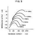
- Fig. 3 shows the recording and reproducing characteristic described in the above book. It will be apparent from Fig. 3 that the level of a reproduced output changes according to the level of a recording current supplied to magnetic heads.
- the recording current levels of the FM luminance signal and the down converted chrominance signal are adjusted by the respective level adjusters 4 and 7 while monitoring the values of the recording currents actually supplied to the rotary magnetic heads 9 and 10 by observing the monitor output derived from the terminal 12.
- the recording current levels of the FM luminance signal and the down converted chrominance signal can be adjusted so as to be optimized regardless of fluctuation of the gains of the FM modulation circuit 3, down conversion circuit 6, mixer circuit 5 and recording amplifier circuit 8 and also regardless of fluctuation of the level of the input video signal a itself.
- the optimum value of the recording current of the FM luminance signal is such that the level of the reproduced output becomes maximum so as to provide a sufficient S/N ratio.
- this optimum value differs depending on the frequency of the recording signal. Therefore, it is a common practice that the optimum value is so selected as to provide a maximum reproduced output level with respect to the center frequency (3 to 4 MHz) of the carrier.
- the level adjuster 7 adjusts the level of the low frequency band color signal so as to maximize the reproduced output level. Therefore, the level of the low frequency band color signal is commonly adjusted to be lower by 10 dB or less than that of the FM luminance signal.
- the level adjusters 4 and 7 In the prior art magnetic recording and reproducing apparatus described above, the level adjusters 4 and 7 must be manually adjusted while observing the monitor output derived through the terminal 12. Thus, the adjustment is troublesome and time consuming. Also, because variable resistors are required as these level adjusters 4 and 7, the entire recording circuit cannot be integrated into an IC, and an increase in the costs of the circuit parts is inevitable. Further, the fact that these variable resistors are incorporated as externally mounted parts leads to the problem that the manufacturing process becomes correspondingly complex.
- the values of the recording currents supplied to these rotary magnetic heads 9 and 10 cannot be adjusted independently of each other.
- the value of the recording current supplied to the rotary magnetic head 9 only (the voltage drop across the resistor 13 only) is monitored so as to adjust the level adjusters 4 and 7. Therefore, such a problem arises that the value of the recording current supplied to the other rotary magnetic head 10 is not necessarily adjusted to its optimum value due to, for example, a difference between the inductances of the rotary magnetic heads 9 and 10.
- US-A-4 433 255 and Patent Abstracts of Japan, Vol. 11, No. 110, 7 April 1987, (JP-A-61 256 890) relate to means for controlling the recording current flowing through a recording head. These means are not able to control a plurality of heads automatically and independently with just a single controlling branch. Rather, in US-A-4 433 255 on which the preamble of claim 1 of this European Patent is based, the control means comprises two separate control branches (18A, 19A and 18B and 19B) and the switching means (20) is arranged after these two separate control branches, the single output of said switching means (20) being connected via a further unit of said control means namely via comparator 21, to said single variable gain amplifier means 10.
- the object of the present invention to provide a magnetic recording and reproducing apparatus in accordance with the preamble of claim 1, in particular a helical scan type videotape recorder, in which the optimum recording currents can be applied to each of the rotary magnetic heads independently and automatically by a very simple control circuit.
- Fig. 1 is a block circuit diagram showing the structure of an embodiment of the magnetic recording and reproducing apparatus according to the present invention.
- Fig. 2 is a block circuit diagram showing the structure of a prior art magnetic recording and reproducing apparatus.
- Fig. 3 is a graph showing the relation between a recording current and a reproduced output in a magnetic recording and reproducing apparatus of this kind.
- Fig. 1 shows the structure of an embodiment of the magnetic recording and reproducing apparatus according to the present invention.
- the magnetic recording and reproducing apparatus shown in Fig. 1 comprises an LPF 1, a BPF 2, an FM modulation circuit 3, a mixer circuit 5, a down conversion circuit 6, a recording amplifier circuit 8, a pair of rotary magnetic heads 9, 10, a rotary transformer 11, resistors 13, 14, a chrominance AGC circuit 15, a variable gain amplifier circuit 16, a synchronizing signal period level detector circuit 17, a comparator circuit 19, a reference voltage source 21, a signal detector circuit 23, a switching circuit 28, and input terminals 26, 27.
- a luminance signal b seperated from an input video signal a by the LPF 1 is applied to the mixer circuit 5 after being subjected to frequency modulation in the FM modulation circuit 3.
- a color signal c separated from the input video signal a by the BPF 2 is applied to the chrominance AGC circuit 15 after being converted into a down converted chrominance signal by the down conversion circuit 6.
- This chrominance AGC circuit 15 is provided so that the level of the down converted chrominance signal is maintained at a constant level lower by 10 dB or-less than that of the FM luminance signal.
- any known circuit which can maintain the level of the low frequency band color signal constant in the burst period can be used as this chrominance AGC circuit 15.
- the output signal of the chrominance AGC circuit 15 is applied to the mixer circuit 5 to be mixed with the FM luminance signal.
- the output signal of the mixer circuit 5 is applied to the variable gain amplifier circuit 16 to be amplified according to the gain provided by a gain control signal d applied from the signal detector circuit 23.
- the output signal from the variable gain amplifier circuit 16 is applied to the rotary magnetic heads 9 and 10 through the recording amplifier circuit 8 and the rotary transformer 11 to be recorded on a magnetic recording medium (not shown).
- the recording currents supplied to the rotary magnetic heads 9 and 10 are detected by he respective resistors 13 and 14 and supplied through the switching circuit 28 to the respective synchronizing signal period level detector circuit 17
- This synchronizing signal period level detector circuits 17 detects the level of the recording currents in the synchronizing period of the video signal being recorded.
- the down converted chrominance signal having an amplitude modulation variation is not present in the synchronizing period of the video signal being recorded, and only the FM luminance signal whose amplitude should primarily be constant is present in the synchronizing period.
- the detection output from the detector circuit 17 is applied to the comparator circuit 19 where the level of this detection output is compared with that one of reference voltage supplied from the reference voltage source 21.
- the comparison error output from the comparator circuit 19 is detected and rectified by the signal detector circuits 23, and the detection output from the signal detector circuits 23 and 24 are applied to the variable gain amplifier 16.
- a head switching signal f is applied from the input terminal 26 to the switching circuit 28, so that the rotary magnetic heads 9 and 10 are switched over for alternately scanning the magnetic recording medium.
- the detection outputs from the signal detector circuits is applied to the variable gain amplifier circuit 16 as the gain control signal d so as to control the gain.
- the levels of the recording currents supplied to the rotary magnetic heads 9 and 10 are independently controlled in a time division mode. Therefore, when the control gains (the resistance values of the resistors 13 and 14, etc.) in the individual control system are selected to be equal, and both the reference voltage supplied from the reference voltage source 21 is set at a voltage value corresponding to the value of the rated recording current to be supplied to the rotary magnetic heads 9 and 10, the values of the recording currents supplied to the respective rotary magnetic heads 9 and 10 can be automatically controlled to be equal to the rated recording current value regardless of, for example, fluctuation of the inductances of the rotary magnetic heads 9 and 10.
- the rated recording current value described above is a recording current value which maximizes the level of a reproduced FM luminance signal as described already. Strictly speaking because the recording and reproducing characteristic curves themselves shown in Fig. 3 tend to shift toward the left or the right due to fluctuation of the inductances of the rotary magnetic heads 9 and 10, the level of the FM luminance signal reproduced by each of the rotary magnetic heads 9 and 10 cannot-be maximized even when the same rated recording current is supplied to each of the rotary magnetic heads 9 and 10. However, because the error between the reproduced levels is usually so slight that the manner of control for supplying the same rated recording current to each of the rotary magnetic heads 9 and 10 can sufficiently practically satisfy the requirement. Of course, by suitably regulating the reference voltage supplied from the reference voltage source 21 as required, the value of the recording current supplied to each of the rotary magnetic heads 9 and 10 can be controlled.
- the recording current supplied to each of the rotary magnetic heads 9 and 10 is automatically controlled so that the output level of the FM luminance signal reproduced by each of the rotary magnetic heads 9 and 10 can be substantially maximized.
- the level of the down converted chrominance signal mixed with the FM luminance signal in the mixer circuit 5 is similarly controlled in the variable gain amplifier circuit 16, so that the ratio between the level of the FM luminance signal and that of the down converted chrominance signal is always maintained constant.
- the recording current level for the down converted chrominance signal can also be freed from any adjustment.
- the synchronizing signal period level detector circuit 17 is provided so as to extract the FM luminance signal recording currents only from the recording currents detected by the respective resistors 13 and 14.
- high-pass filters may be provided so as to extract the FM luminance signal only.
- the synchronizing signal period level detector circuit 17 may be combined with high-pass filters so as to remove a noise component such as the down converted chrominance signal mixed in the synchronizing period, so that only the FM luminance signal present in the synchronizing period can be reliably extracted.
- the recording currents supplied to the rotary magnetic heads 9 and 10 can be controlled by a single control circuit system.
- a switching circuit 28 is provided, so that the outputs of the resistors 13 and 14 detecting the recording currents supplied to the respective rotary magnetic heads 9 and 10 are alternately supplied to the synchronizing signal period level detector circuit 17 through the switching circuit 28.
- the switching circuit 28 is switched over in each of the periods in which the rotary magnetic heads 9 and 10 alternately scan the magnetic recording medium in response to the head switching signal f applied from the input terminal 26. It will be apparent that, in this embodiment, the recording currents supplied to the rotary magnetic heads 9 and 10 are controlled in a time division mode.
- the control error voltage applied to the signal detector circuit 23 changes stepwise according to the inductance values of the rotary magnetic heads 9 and 10 whenever the switching circuit 28 is switched over. Therefore, it is necessary to set the smoothing time constant of the signal detector circuit 23 at a relatively small value. However, the value of this smoothing time constant cannot be made small without limitation. Thus, there arises the problem that the output of the signal detector circuit 23 cannot completely follow up the stepwise change of the control error voltage. On the other hand such a problem does not arise because such a stepwise change of the control error voltage does not occur.
- the present invention is in no way limited to such specific embodiment and is generally applicable to a magnetic recording and reproducing apparatus in which an input signal is sequentially recorded on a magnetic recording medium by a plurality of rotary magnetic heads.
- an FM signal an FM luminance signal
- an essential requirement is only such that the signal to be recorded includes a signal which is not subjected to any amplitude variation in itself. Therefore, a signal such as a pilot signal having a constant amplitude may be mixed in the signal to be recorded so as to detect an error of the recording current level by detecting its amplitude variation error.
- recording currents to be supplied to a plurality of rotary magnetic heads for recording an input signal on a magnetic recording medium are controlled in a time division mode, so that the recording currents supplied to the respective rotary magnetic heads can be independently controlled, and so that any error of the recording current levels due to fluctuation of the inductances of the rotary magnetic heads can be removed.
- the level of the recording current supplied to each of the rotary magnetic heads can be always automatically controlled to the predetermined value without resorting to manual adjustment. Therefore, variable resistors for the manual adjustment purpose required in some prior art apparatuses need not be provided in the recording circuit system, and the entire recording circuit system can be integrated into an IC, so that the circuit parts cost can be decreased, and the manufacturing process can also be simplified.
Landscapes
- Engineering & Computer Science (AREA)
- Multimedia (AREA)
- Signal Processing (AREA)
- Television Signal Processing For Recording (AREA)
Claims (3)
- Magnetisches Aufzeichnungs- und Wiedergabegerät für aufeinanderfolgendes Aufzeichnen eines Eingabesignals auf einem magnetischen Aufzeichnungsmedium mittels einer Mehrzahl von rotierenden Magnetköpfen (9, 10), wobei das Gerät enthält: eine Mehrzahl von Aufzeichnungsstrom-Detektiervorrichtungen (13, 14) zum Detektieren der Werte der jeweiligen Aufzeichnungsströme, die den rotierenden Magnetköpfen (9, 10) zugeführt werden;einzelne Verstärkervorrichtungen (16) mit variablem Verstärkungsgrad zur variablen Steuerung der Amplituden der jeweiligen Aufzeichnungsströme, die den rotierenden Magnetköpfen (9, 10) zugeführt werden; einen Steuerzweig, der Steuervorrichtungen (17, 19, 23) zum Detektieren von Amplitudenvariationen der jeweiligen Aufzeichnungsströme enthält, die den rotierenden Magnetköpfen zugeführt werden, und zum aufeinanderfolgenden variablen Steuern des Verstärkungsgrades der Verstärkervorrichtung variablen Verstärkungsgrades auf der Basis der detektierten Amplitudenvariation in jeweiligen Abtastperioden, in denen die rotierenden Magnetköpfe aufeinanderfolgend und abwechselnd das magnetische Aufzeichnungsmedium abtasten; undSchaltvorrichtungen (27, 28) zum aufeinanderfolgenden Auswählen jeweiliger Ausgaben der Aufzeichnungsstrom-Detektiervorrichtungen in Zeitbeziehung mit den jeweiligen Abtastperioden, in denen die rotierenden Köpfe das magnetische Aufzeichnungsmedium abtasten, wobei die Schaltvorrichtungen einen einzelnen Ausgang haben, an dem die jeweiligen Stromwerte von den Aufzeichnungsstrom-Detektiervorrichtungen aufeinanderfolgend auftreten;dadurch gekennzeichnet,
daß die Schaltvorrichtungen (27, 28) unmittelbar nach der Mehrzahl von Aufzeichnungsstrom-Detektiervorrichtungen (13, 14) angeordnet sind, und daß der Steuerzweig die Form eines einzelnen Steuerzweigs hat, der mit dem einzelnen Ausgang der Schaltvorrichtung verbunden ist, so daß die auf die Schaltvorrichtungen (27, 28) folgenden Steuervorrichtungen (17, 19, 23) gänzlich zwischen den Schaltvorrichtungen und der Verstärkervorrichtung (16) variablen Verstärkungsgrades positioniert ist. - Magnetisches Aufzeichnungs- und Wiedergabegerät nach Anspruch 1, dadurch gekennzeichnet, daß die Mehrzahl von Aufzeichnungsstrom-Detektiervorrichtungen eine Mehrzahl von Stromdetektierelementen (13, 14) zum Detektieren der Werte der jeweiligen Aufzeichnungsströme enthält, die den rotierenden Magnetköpfen (9, 10) zugeführt werden.
- Magnetisches Aufzeichnungs- und Wiedergabegerät nach Anspruch 1 oder 2, dadurch gekennzeichnet, daß das durch eine Mehrzahl von rotierenden Magnetköpfen (9, 10) auf dem magnetischen Aufzeichnungsmedium aufzuzeichnende Eingabesignal ein Videosignal mit einer Synchronisierperiode ist, und daß die Steuervorrichtung eine einzelne Synchronisierperiodenpegel-Detektiervorrichtung (17) zum Detektieren der Werte der jeweiligen Aufzeichnungsströme innerhalb der Synchronisierperiode des Videosignals, eine Pegelvergleichsvorrichtung (19), in der die Aufzeichnungsstromwerte innerhalb der Synchronisierperiode mit einem Bezugsspannungspegel (21) verglichen werden, sowie eine Signaldetektiervorrichtung (23) zum Gleichrichten des Ausgabesignals der Pegelvergleichsvorrichtung und zum Zuführen des gleichgerichteten Ausgabesignals an die Verstärkervorrichtung variablen Verstärkungsgrads (16) enthält.
Applications Claiming Priority (2)
| Application Number | Priority Date | Filing Date | Title |
|---|---|---|---|
| JP25140/90 | 1990-02-06 | ||
| JP02514090A JP3148814B2 (ja) | 1990-02-06 | 1990-02-06 | 磁気記録再生装置 |
Publications (3)
| Publication Number | Publication Date |
|---|---|
| EP0441314A2 EP0441314A2 (de) | 1991-08-14 |
| EP0441314A3 EP0441314A3 (en) | 1992-10-07 |
| EP0441314B1 true EP0441314B1 (de) | 1997-05-02 |
Family
ID=12157676
Family Applications (1)
| Application Number | Title | Priority Date | Filing Date |
|---|---|---|---|
| EP91101508A Expired - Lifetime EP0441314B1 (de) | 1990-02-06 | 1991-02-05 | Magnetisches Aufzeichnungs- und Wiedergabegerät |
Country Status (4)
| Country | Link |
|---|---|
| US (1) | US5260843A (de) |
| EP (1) | EP0441314B1 (de) |
| JP (1) | JP3148814B2 (de) |
| DE (1) | DE69125864T2 (de) |
Families Citing this family (4)
| Publication number | Priority date | Publication date | Assignee | Title |
|---|---|---|---|---|
| DE4226688B4 (de) * | 1992-08-12 | 2004-07-08 | Deutsche Thomson-Brandt Gmbh | Schaltung zur Steuerung der Aufnahmeströme der Videoköpfe eines Videorecorders |
| KR950006083B1 (ko) * | 1993-03-05 | 1995-06-08 | 주식회사엘지전자 | 브이 씨 알(vcr)의 알 에프(rf)신호 레벨 자동 조절장치 |
| US6717761B2 (en) * | 2000-04-26 | 2004-04-06 | Hitachi, Ltd. | Recording/reproducing apparatus |
| US6979044B2 (en) * | 2002-03-27 | 2005-12-27 | Stephen Edward Tyrer | Golf cart rearwardly extending canopy cover |
Family Cites Families (10)
| Publication number | Priority date | Publication date | Assignee | Title |
|---|---|---|---|---|
| US3265818A (en) * | 1962-05-28 | 1966-08-09 | Ampex | Signal system optimization in magnetic tape apparatus for processing continuous nonpictorial wideband signals |
| JPS4932445B1 (de) * | 1970-03-25 | 1974-08-30 | ||
| US3852808A (en) * | 1973-04-04 | 1974-12-03 | Rca Corp | Color amplitude correction in plural transducer signal playback systems |
| US4433255A (en) * | 1981-02-25 | 1984-02-21 | Tokyo Shibaura Denki Kabushiki Kaisha | Signal sampling gate circuit |
| AU556742B2 (en) * | 1982-02-01 | 1986-11-20 | Sony Corporation | Digital tape jitter compensation |
| JPS5990477A (ja) * | 1982-11-16 | 1984-05-24 | Sony Corp | ビデオ信号補正回路 |
| CA1231441A (en) * | 1984-07-10 | 1988-01-12 | Kazuyoshi Kuwahara | Recording circuit having means to automatically set the recording current of a magnetic recording head |
| JPS61256890A (ja) * | 1985-05-09 | 1986-11-14 | Mitsubishi Electric Corp | 映像記録再生装置 |
| KR910001466B1 (ko) * | 1985-07-12 | 1991-03-07 | 마쯔시다덴기산교 가부시기가이샤 | 영상신호의 신호처리장치 |
| JPH0748242B2 (ja) * | 1989-01-19 | 1995-05-24 | 三菱電機株式会社 | 磁気記録再生装置 |
-
1990
- 1990-02-06 JP JP02514090A patent/JP3148814B2/ja not_active Expired - Fee Related
-
1991
- 1991-02-05 DE DE69125864T patent/DE69125864T2/de not_active Expired - Fee Related
- 1991-02-05 EP EP91101508A patent/EP0441314B1/de not_active Expired - Lifetime
- 1991-02-06 US US07/651,516 patent/US5260843A/en not_active Expired - Lifetime
Also Published As
| Publication number | Publication date |
|---|---|
| EP0441314A3 (en) | 1992-10-07 |
| US5260843A (en) | 1993-11-09 |
| JP3148814B2 (ja) | 2001-03-26 |
| DE69125864D1 (de) | 1997-06-05 |
| EP0441314A2 (de) | 1991-08-14 |
| DE69125864T2 (de) | 1997-10-02 |
| JPH03230302A (ja) | 1991-10-14 |
Similar Documents
| Publication | Publication Date | Title |
|---|---|---|
| US4713700A (en) | A recording circuit having means to automatically set the recording current of a magnetic recording head | |
| JPH02134093A (ja) | 映像再生装置 | |
| EP0441314B1 (de) | Magnetisches Aufzeichnungs- und Wiedergabegerät | |
| EP0579198B1 (de) | Kontrollanordnung für magnetische Aufzeichnung | |
| US6101312A (en) | Automatic picture quality controller | |
| US4723175A (en) | Video signal reproducing apparatus for reproducing recorded video signal from a magnetic recording medium | |
| US5164864A (en) | Circuit for comparing high frequency amplitude modulated signals | |
| JPS6143919B2 (de) | ||
| US4519005A (en) | Magnetic tape reproducing apparatus | |
| EP0091103B1 (de) | Magnetisches Aufzeichnungsgerät für ein Farbvideosignal | |
| US5083211A (en) | Method and apparatus for optimizing video recording and reproduction | |
| KR940003669B1 (ko) | 브이씨알의 테이프 녹화 시스템 | |
| US5349444A (en) | Video signal output circuit with adaptive equalizer | |
| US5982975A (en) | Video signal copying apparatus | |
| KR950007940B1 (ko) | 자동 트래킹 제어방법과 장치 | |
| US6519409B1 (en) | Apparatus for recording a high quality signal | |
| JPH0691664B2 (ja) | 磁気記録再生装置 | |
| KR100240335B1 (ko) | 비디오 카세트 레코더의 버스트 크기 자동 감지 및 조절 장치 | |
| JP2953855B2 (ja) | 多重信号の記録調整方法 | |
| KR890005007B1 (ko) | 자기 기록 재생 장치 | |
| US5253123A (en) | Apparatus for digitally recording time-multiplexed digital information and pilot signals with different recording current levels | |
| JPH0435803B2 (de) | ||
| KR910008346Y1 (ko) | Vtr의 화질 개선장치 | |
| JP2713629B2 (ja) | 磁気記録再生装置 | |
| JPS6170889A (ja) | 磁気記録再生装置における自動利得制御回路 |
Legal Events
| Date | Code | Title | Description |
|---|---|---|---|
| PUAI | Public reference made under article 153(3) epc to a published international application that has entered the european phase |
Free format text: ORIGINAL CODE: 0009012 |
|
| 17P | Request for examination filed |
Effective date: 19910205 |
|
| AK | Designated contracting states |
Kind code of ref document: A2 Designated state(s): DE GB |
|
| PUAL | Search report despatched |
Free format text: ORIGINAL CODE: 0009013 |
|
| AK | Designated contracting states |
Kind code of ref document: A3 Designated state(s): DE GB |
|
| 17Q | First examination report despatched |
Effective date: 19950324 |
|
| GRAG | Despatch of communication of intention to grant |
Free format text: ORIGINAL CODE: EPIDOS AGRA |
|
| GRAH | Despatch of communication of intention to grant a patent |
Free format text: ORIGINAL CODE: EPIDOS IGRA |
|
| GRAH | Despatch of communication of intention to grant a patent |
Free format text: ORIGINAL CODE: EPIDOS IGRA |
|
| GRAA | (expected) grant |
Free format text: ORIGINAL CODE: 0009210 |
|
| AK | Designated contracting states |
Kind code of ref document: B1 Designated state(s): DE GB |
|
| REF | Corresponds to: |
Ref document number: 69125864 Country of ref document: DE Date of ref document: 19970605 |
|
| PLBE | No opposition filed within time limit |
Free format text: ORIGINAL CODE: 0009261 |
|
| STAA | Information on the status of an ep patent application or granted ep patent |
Free format text: STATUS: NO OPPOSITION FILED WITHIN TIME LIMIT |
|
| 26N | No opposition filed | ||
| REG | Reference to a national code |
Ref country code: GB Ref legal event code: IF02 |
|
| PGFP | Annual fee paid to national office [announced via postgrant information from national office to epo] |
Ref country code: GB Payment date: 20080114 Year of fee payment: 18 |
|
| PGFP | Annual fee paid to national office [announced via postgrant information from national office to epo] |
Ref country code: DE Payment date: 20080307 Year of fee payment: 18 |
|
| GBPC | Gb: european patent ceased through non-payment of renewal fee |
Effective date: 20090205 |
|
| PG25 | Lapsed in a contracting state [announced via postgrant information from national office to epo] |
Ref country code: DE Free format text: LAPSE BECAUSE OF NON-PAYMENT OF DUE FEES Effective date: 20090901 |
|
| PG25 | Lapsed in a contracting state [announced via postgrant information from national office to epo] |
Ref country code: GB Free format text: LAPSE BECAUSE OF NON-PAYMENT OF DUE FEES Effective date: 20090205 |