EP0440872A2 - Circuit d'allumage et de sécurité pour brûleur à gaz - Google Patents
Circuit d'allumage et de sécurité pour brûleur à gaz Download PDFInfo
- Publication number
- EP0440872A2 EP0440872A2 EP90105518A EP90105518A EP0440872A2 EP 0440872 A2 EP0440872 A2 EP 0440872A2 EP 90105518 A EP90105518 A EP 90105518A EP 90105518 A EP90105518 A EP 90105518A EP 0440872 A2 EP0440872 A2 EP 0440872A2
- Authority
- EP
- European Patent Office
- Prior art keywords
- relay
- switch
- diode
- charging capacitor
- circuit
- Prior art date
- Legal status (The legal status is an assumption and is not a legal conclusion. Google has not performed a legal analysis and makes no representation as to the accuracy of the status listed.)
- Granted
Links
Images
Classifications
-
- F—MECHANICAL ENGINEERING; LIGHTING; HEATING; WEAPONS; BLASTING
- F23—COMBUSTION APPARATUS; COMBUSTION PROCESSES
- F23N—REGULATING OR CONTROLLING COMBUSTION
- F23N5/00—Systems for controlling combustion
- F23N5/24—Preventing development of abnormal or undesired conditions, i.e. safety arrangements
- F23N5/242—Preventing development of abnormal or undesired conditions, i.e. safety arrangements using electronic means
-
- F—MECHANICAL ENGINEERING; LIGHTING; HEATING; WEAPONS; BLASTING
- F23—COMBUSTION APPARATUS; COMBUSTION PROCESSES
- F23N—REGULATING OR CONTROLLING COMBUSTION
- F23N5/00—Systems for controlling combustion
- F23N5/20—Systems for controlling combustion with a time programme acting through electrical means, e.g. using time-delay relays
- F23N5/203—Systems for controlling combustion with a time programme acting through electrical means, e.g. using time-delay relays using electronic means
-
- F—MECHANICAL ENGINEERING; LIGHTING; HEATING; WEAPONS; BLASTING
- F23—COMBUSTION APPARATUS; COMBUSTION PROCESSES
- F23N—REGULATING OR CONTROLLING COMBUSTION
- F23N2227/00—Ignition or checking
- F23N2227/04—Prepurge
-
- F—MECHANICAL ENGINEERING; LIGHTING; HEATING; WEAPONS; BLASTING
- F23—COMBUSTION APPARATUS; COMBUSTION PROCESSES
- F23N—REGULATING OR CONTROLLING COMBUSTION
- F23N2227/00—Ignition or checking
- F23N2227/36—Spark ignition, e.g. by means of a high voltage
Definitions
- the invention relates to an ignition and safety circuit fed from an alternating voltage, preferably the mains alternating voltage, for a gas burner supplied with gas via a solenoid valve, an electric spark igniter and a flame sensor.
- an alternating voltage preferably the mains alternating voltage
- a gas burner supplied with gas via a solenoid valve, an electric spark igniter and a flame sensor.
- a flame sensor switches off the spark igniter and the burner changes to the normal operating state.
- the fuel supply must be interrupted.
- the duration of the safety period determines this duration depending on the burner output. It is therefore important that the safety period is adhered to regardless of external influences. If one uses a current-heated one to determine the duration of the safety period Bimetallic strip, its rate of deformation depends on the current flowing through it and thus directly on the supply voltage. Fluctuations in the supply voltage thus lead to changes in the safety time specified with the bimetal switch. If, on the other hand, the duration of the safety period is determined by charging or discharging a capacitor, then in order to achieve the safety time of 10 seconds, for example, the capacitor must have a rather high capacity. Such capacitors are usually designed as electrolytic capacitors, but they are inaccurate and have poor long-term stability.
- the duration of the safety period is determined electrically with the aid of a precision capacitor, for example a thin-film capacitor of low capacitance, in connection with an operational amplifier and a switch-on relay for the gas valve and a bistable safety relay, in connection with one in the course of it Charging the pre-purge time-determining capacitor of larger capacity, work in series during the pre-purge time without responding and at the end of the pre-purge time are switched to parallel operation, so that the switch-on relay responds and the gas valve opens.
- a precision capacitor for example a thin-film capacitor of low capacitance
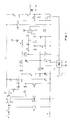
- the circuit arrangement according to FIG. 1 is operated with AC voltage, for which purpose for example the AC mains voltage of 220 V is connected between the line terminal L and ground N. It is assumed that the burner should be started as soon as a room thermostat or other switch TH requesting the supply of heating energy closes.
- the switch TH When the switch TH is closed, the fan motor LM first becomes live with which the pre-rinse time begins. At this time, the excitation winding VG of the fuel valve V and the ignition transformer ZT are still without current. Both lie between the line L1 and ground, the line L1 being disconnected from the mains, because in the rest position the switch contact gr of the switch-on relay GR for the gas valve is connected to its normally closed contact g2 and the normally open contact g1 is therefore de-energized.
- a bistable safety relay SR also has a changeover contact sr, which is present in the work position on the work contact s1. As soon as the thermostat contact TH closes, current flows on the one hand, as mentioned, to the fan motor and, on the other hand, via the normally open contact s1 to a direct current supply device PS, which supplies, for example, stabilized direct voltages of + 22V and -5V for supplying the other circuit parts.
- a capacitor C4 is connected via a blocking diode D4 to the connection point P2 of the grounding of the capacitor C2 and the safety relay SR. It has a much lower capacity, for example luF, than that Charging capacitor C2 with for example 47uF.
- the capacitor C4 is connected in parallel with a voltage divider R7, R8, at the tap P6 of which is the non-inverting input (+) of an operational amplifier OP.
- the inverting input (-) of this operational amplifier is connected via a series resistor R9 to the tap P7 of a further voltage divider R4, R5, which is connected between the positive supply voltage + 22V and ground.
- the voltage at tap P7 is, for example, + 15V.
- the pre-rinsing period VSP ends and the safety period SP begins to run.
- the charge stored on the capacitor C2 can flow off as a current pulse via the two relays SR and GR. From point P2 the current flows on the one hand directly via the safety relay SR and the transistor T2 to ground and on the other hand via the diodes D2 and D3 as well a resistor R3 through the switch-on relay GR and again the transistor T2 also to ground.
- the capacitor C2 previously charged to approximately 36V is discharged via the two relay windings.
- the switch-on relay GR switches its contact gr to the normally open contact g1, so that the excitation winding VG of the gas valve V is now connected to the mains AC voltage and the gas valve opens.
- the charging capacitor C5 of the spark generator is charged via the rectifier diode D6 and the resistor R12.
- a positive signal is present at the output FZ of the flame sensor circuit FS, which turns on the thyristor TY1, so that the capacitor C5 can periodically discharge through the primary winding of the ignition transformer ZT and ignition pulses for an ignition electrode assigned to the burner are produced at the output terminal Z.
- a resistor R11 and a freewheeling diode D7 are connected in parallel to the series connection of capacitor C5 and primary winding of the ignition transformer ZT.
- the resistor R1 and the diode D1 are separated from the mains AC voltage on the one hand, and the rectifier diode D3 is connected to the line L1 via the resistor R2 and the capacitor C1, so that this diode D3 is connected via the resistor R3 drives a direct current through the switch-on relay GR and keeps it in the switch position mentioned.
- a smoothing capacitor C3 is connected in parallel to the relay GR.
- the impedance of the series connection of resistor R2 and capacitor C1, for example 10 kOhm, is significantly lower than that Resistor R1 with, for example, 100 kOhm, so that the direct current generated by diode D3 of, for example, 10 mA is significantly higher than the previous charging current. This direct current is thus able to keep the relay GR in the switching position mentioned.
- the negative half-wave of the applied AC voltage generates a DC current of, for example, 10 mA, which flows to ground via the Zener diode ZD.
- the voltage at the zener diode is, for example, 47V.
- the timer capacitor C4 has a significantly lower capacitance than the charging capacitor C2.
- the timer capacitor can thus be manufactured as a highly stable thin film capacitor. Together with a voltage divider consisting of highly constant resistors R7 and R8, it determines its discharge time and thus the duration of the safety period SP.
- the capacitor C4 discharges via the voltage divider R7, R8 mentioned.
- the non-inverting input (+) of the operational amplifier OP is located at the tap P6 of the voltage divider. As mentioned above, the inverting input is connected to the tap P7 of the voltage divider R4, R5.
- resistor R5 is connected in parallel via resistor D6 via diode D5. Its resistance value of 39 kOhm, for example, is significantly lower than that of resistor R5, for example 220 kOhm.
- resistor R6 With the parallel connection of resistor R6 to resistor R5, the voltage at the inverting input (-) of the operational amplifier OP inevitably decreases.
- the positive output voltage of the operational amplifier OP disappears and thus the switch-on voltage for the transistor T2.
- transistor T2 blocks, causing the direct current of, for example, 10 mA to no longer flow through transistor T2, but through safety relay SR and to capacitor C2.
- the impedance of the capacitor C1 of approximately 10 kOhm is very high compared to that of the two relay windings.
- the capacitor C1 connected to the AC voltage thus works almost as a constant current source.
- the safety relay SR switches to the safety position. It remains there due to its bistable nature.
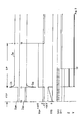
- FIG. 2 illustrates the current and voltage values various switching points in the course of normal start-up of the burner.
- the thermostat contact TH is closed.
- the operational amplifier OP switches its output voltage from, for example, -5V to + 20V and switches transistor T2 through .
- the pre-rinsing period VSP is thus ended and the safety period SP begins at time t1.
- a current pulse I G flows through the switch-on relay GR, which triggers this relay. After switching its contact gr, the diode D3 generates a holding current I H which is lower than the response current. Simultaneously with the positive current pulse I G through the relay GR, a negative current pulse I N occurs through the safety relay SR, which, however, does not affect its switching position. It is already in the operating position. Since the thermostat TH has closed, switching pulses V FZ for the thyristor TY1 in the spark generator have been produced at the output of the flame sensor circuit FS. However, the primary winding of the ignition transformer TR1 is only connected to the supply line L1 at the time t1, so that ignition pulses ZT also only occur at the output terminal Z at this time t1.
- the output signal V OP of the operational amplifier would disappear at the end of the safety period SP at the time t3. Since the transistor T1 is still blocked in this case, there is a positive current pulse I P through the safety relay SR, so that this switches to its safety position at time t 3 and remains there due to its bistable mode of operation.
- the safety relay is switched over, the power supply circuit PS, the field winding VG of the gas valve V and the ignition transformer ZT become currentless.
Landscapes
- Engineering & Computer Science (AREA)
- Chemical & Material Sciences (AREA)
- Combustion & Propulsion (AREA)
- Mechanical Engineering (AREA)
- General Engineering & Computer Science (AREA)
- Regulation And Control Of Combustion (AREA)
Applications Claiming Priority (2)
| Application Number | Priority Date | Filing Date | Title |
|---|---|---|---|
| DE4003467 | 1990-02-06 | ||
| DE4003467 | 1990-02-06 |
Publications (3)
| Publication Number | Publication Date |
|---|---|
| EP0440872A2 true EP0440872A2 (fr) | 1991-08-14 |
| EP0440872A3 EP0440872A3 (en) | 1992-04-29 |
| EP0440872B1 EP0440872B1 (fr) | 1994-09-21 |
Family
ID=6399522
Family Applications (1)
| Application Number | Title | Priority Date | Filing Date |
|---|---|---|---|
| EP90105518A Expired - Lifetime EP0440872B1 (fr) | 1990-02-06 | 1990-03-23 | Circuit d'allumage et de sécurité pour brûleur à gaz |
Country Status (2)
| Country | Link |
|---|---|
| EP (1) | EP0440872B1 (fr) |
| DE (1) | DE59007264D1 (fr) |
Cited By (3)
| Publication number | Priority date | Publication date | Assignee | Title |
|---|---|---|---|---|
| EP0566768A1 (fr) * | 1992-04-24 | 1993-10-27 | Honeywell B.V. | Circuit de commande pour un brûleur à gaz avec un commutateur de courant pur surveiller l'alimentation d'air |
| EP0687965A3 (fr) * | 1994-06-18 | 1996-04-03 | Diehl Gmbh & Co | Appareil chauffé au gaz |
| EP1182402A1 (fr) * | 2000-08-25 | 2002-02-27 | Honeywell B.V. | Circuit de commande |
Family Cites Families (4)
| Publication number | Priority date | Publication date | Assignee | Title |
|---|---|---|---|---|
| US3393037A (en) * | 1966-12-07 | 1968-07-16 | Electronics Corp America | Combustion control system |
| US3840322A (en) * | 1974-01-11 | 1974-10-08 | Electronics Corp America | Electrical control circuitry |
| US4243372A (en) * | 1979-02-05 | 1981-01-06 | Electronics Corporation Of America | Burner control system |
| CH648107A5 (de) * | 1984-02-15 | 1985-02-28 | Landis & Gyr Ag | Schaltung fuer einen feuerungsautomaten. |
-
1990
- 1990-03-23 DE DE59007264T patent/DE59007264D1/de not_active Expired - Fee Related
- 1990-03-23 EP EP90105518A patent/EP0440872B1/fr not_active Expired - Lifetime
Cited By (3)
| Publication number | Priority date | Publication date | Assignee | Title |
|---|---|---|---|---|
| EP0566768A1 (fr) * | 1992-04-24 | 1993-10-27 | Honeywell B.V. | Circuit de commande pour un brûleur à gaz avec un commutateur de courant pur surveiller l'alimentation d'air |
| EP0687965A3 (fr) * | 1994-06-18 | 1996-04-03 | Diehl Gmbh & Co | Appareil chauffé au gaz |
| EP1182402A1 (fr) * | 2000-08-25 | 2002-02-27 | Honeywell B.V. | Circuit de commande |
Also Published As
| Publication number | Publication date |
|---|---|
| EP0440872B1 (fr) | 1994-09-21 |
| DE59007264D1 (de) | 1994-10-27 |
| EP0440872A3 (en) | 1992-04-29 |
Similar Documents
| Publication | Publication Date | Title |
|---|---|---|
| DE2747607C2 (de) | Schaltungsanordnung zur Ansteuerung eines bistabilen Relais | |
| EP0006843B1 (fr) | Valve électromagnétique avec commande électronique | |
| DE2831113A1 (de) | Stromversorgungskreis fuer magnetventile | |
| DE3326012C2 (de) | Einzelimpuls-Erzeugungsschaltung | |
| DE1438857B2 (de) | Gerät zum Laden von Akkumulatoren | |
| EP0440872B1 (fr) | Circuit d'allumage et de sécurité pour brûleur à gaz | |
| DE3026787C2 (de) | Eigensicherer Flammenwächter | |
| DE2809993C3 (de) | Flammenwächterschaltung zur Überwachung einer Brennerflamme | |
| EP0635171B1 (fr) | Bloc electronique d'alimentation a decoupage | |
| EP0057896B2 (fr) | Circuit pour la commande d'un marteau actionné par voie électromagnétique | |
| EP0120347A2 (fr) | Interrupteur horaire | |
| EP0002648B1 (fr) | Minuterie pour cage d'escalier | |
| EP0433592A1 (fr) | Minuterie commandée par ordinateur | |
| DE873293C (de) | Elektrische Steuerung fuer Elektronenroehren mit Steuerelektrode | |
| EP0533961B1 (fr) | Circuit de commande pour brûleur à gaz | |
| DE857655C (de) | Spannungsreglerschaltung fuer elektrische Entladungsgeraete | |
| DE1931236C3 (de) | Zündanlage für Brennkraftmaschinen | |
| DE2323287C3 (de) | Schaltungsanordnung zum Zünden und Betrieb einer von einer Wechselstromquelle gespeisten Entladungslampe | |
| DE1513611C (de) | Anordnung zur Drehzahlsteuerung eines Gleichstrommotors | |
| AT207176B (de) | Elektrische Anlaßsperrvorrichtung für Andrehmotoren von Brennkraftmaschinen | |
| DE2507811C3 (de) | An Wechselspannung angeschlossene Verstärkerschaltung für Flammenwächter | |
| DE2513287C3 (de) | Gleichspannungswandler | |
| DE1673757C3 (de) | Signaleinrichtung für elektrische Weckeruhren | |
| DE2445667C3 (de) | Schaltungsanordnung zum Zünden einer elektronischen Blitzröhre | |
| EP0314610A1 (fr) | Automate à brûleur |
Legal Events
| Date | Code | Title | Description |
|---|---|---|---|
| PUAI | Public reference made under article 153(3) epc to a published international application that has entered the european phase |
Free format text: ORIGINAL CODE: 0009012 |
|
| AK | Designated contracting states |
Kind code of ref document: A2 Designated state(s): DE DK FR GB IT NL |
|
| PUAL | Search report despatched |
Free format text: ORIGINAL CODE: 0009013 |
|
| AK | Designated contracting states |
Kind code of ref document: A3 Designated state(s): DE DK FR GB IT NL |
|
| 17P | Request for examination filed |
Effective date: 19920327 |
|
| 17Q | First examination report despatched |
Effective date: 19940309 |
|
| RAP1 | Party data changed (applicant data changed or rights of an application transferred) |
Owner name: HONEYWELL B.V. |
|
| GRAA | (expected) grant |
Free format text: ORIGINAL CODE: 0009210 |
|
| AK | Designated contracting states |
Kind code of ref document: B1 Designated state(s): DE DK FR GB IT NL |
|
| PG25 | Lapsed in a contracting state [announced via postgrant information from national office to epo] |
Ref country code: DK Effective date: 19940921 |
|
| REF | Corresponds to: |
Ref document number: 59007264 Country of ref document: DE Date of ref document: 19941027 |
|
| ET | Fr: translation filed | ||
| ITF | It: translation for a ep patent filed | ||
| GBT | Gb: translation of ep patent filed (gb section 77(6)(a)/1977) |
Effective date: 19941110 |
|
| PLBE | No opposition filed within time limit |
Free format text: ORIGINAL CODE: 0009261 |
|
| STAA | Information on the status of an ep patent application or granted ep patent |
Free format text: STATUS: NO OPPOSITION FILED WITHIN TIME LIMIT |
|
| 26N | No opposition filed | ||
| REG | Reference to a national code |
Ref country code: GB Ref legal event code: IF02 |
|
| PGFP | Annual fee paid to national office [announced via postgrant information from national office to epo] |
Ref country code: FR Payment date: 20050302 Year of fee payment: 16 |
|
| PGFP | Annual fee paid to national office [announced via postgrant information from national office to epo] |
Ref country code: GB Payment date: 20060206 Year of fee payment: 17 |
|
| PGFP | Annual fee paid to national office [announced via postgrant information from national office to epo] |
Ref country code: NL Payment date: 20060209 Year of fee payment: 17 |
|
| PGFP | Annual fee paid to national office [announced via postgrant information from national office to epo] |
Ref country code: DE Payment date: 20060330 Year of fee payment: 17 |
|
| PGFP | Annual fee paid to national office [announced via postgrant information from national office to epo] |
Ref country code: IT Payment date: 20060331 Year of fee payment: 17 |
|
| GBPC | Gb: european patent ceased through non-payment of renewal fee |
Effective date: 20070323 |
|
| NLV4 | Nl: lapsed or anulled due to non-payment of the annual fee |
Effective date: 20071001 |
|
| REG | Reference to a national code |
Ref country code: FR Ref legal event code: ST Effective date: 20071130 |
|
| PG25 | Lapsed in a contracting state [announced via postgrant information from national office to epo] |
Ref country code: NL Free format text: LAPSE BECAUSE OF NON-PAYMENT OF DUE FEES Effective date: 20071001 Ref country code: DE Free format text: LAPSE BECAUSE OF NON-PAYMENT OF DUE FEES Effective date: 20071002 |
|
| PG25 | Lapsed in a contracting state [announced via postgrant information from national office to epo] |
Ref country code: GB Free format text: LAPSE BECAUSE OF NON-PAYMENT OF DUE FEES Effective date: 20070323 |
|
| PG25 | Lapsed in a contracting state [announced via postgrant information from national office to epo] |
Ref country code: FR Free format text: LAPSE BECAUSE OF NON-PAYMENT OF DUE FEES Effective date: 20070402 |
|
| PG25 | Lapsed in a contracting state [announced via postgrant information from national office to epo] |
Ref country code: FR Free format text: LAPSE BECAUSE OF NON-PAYMENT OF DUE FEES Effective date: 20060331 |
|
| PG25 | Lapsed in a contracting state [announced via postgrant information from national office to epo] |
Ref country code: IT Free format text: LAPSE BECAUSE OF NON-PAYMENT OF DUE FEES Effective date: 20070323 |