EP0439971B1 - Palier ou roulement notamment à corps roulants jointifs - Google Patents
Palier ou roulement notamment à corps roulants jointifs Download PDFInfo
- Publication number
- EP0439971B1 EP0439971B1 EP90403315A EP90403315A EP0439971B1 EP 0439971 B1 EP0439971 B1 EP 0439971B1 EP 90403315 A EP90403315 A EP 90403315A EP 90403315 A EP90403315 A EP 90403315A EP 0439971 B1 EP0439971 B1 EP 0439971B1
- Authority
- EP
- European Patent Office
- Prior art keywords
- bearing
- rolling
- closure member
- axial
- notch
- Prior art date
- Legal status (The legal status is an assumption and is not a legal conclusion. Google has not performed a legal analysis and makes no representation as to the accuracy of the status listed.)
- Expired - Lifetime
Links
- 238000005096 rolling process Methods 0.000 title claims description 29
- 230000009975 flexible effect Effects 0.000 claims description 9
- 230000014759 maintenance of location Effects 0.000 claims description 5
- 238000000034 method Methods 0.000 description 4
- 239000000463 material Substances 0.000 description 2
- 238000004519 manufacturing process Methods 0.000 description 1
- 239000007787 solid Substances 0.000 description 1
Images

Classifications
-
- F—MECHANICAL ENGINEERING; LIGHTING; HEATING; WEAPONS; BLASTING
- F16—ENGINEERING ELEMENTS AND UNITS; GENERAL MEASURES FOR PRODUCING AND MAINTAINING EFFECTIVE FUNCTIONING OF MACHINES OR INSTALLATIONS; THERMAL INSULATION IN GENERAL
- F16C—SHAFTS; FLEXIBLE SHAFTS; ELEMENTS OR CRANKSHAFT MECHANISMS; ROTARY BODIES OTHER THAN GEARING ELEMENTS; BEARINGS
- F16C43/00—Assembling bearings
- F16C43/04—Assembling rolling-contact bearings
- F16C43/06—Placing rolling bodies in cages or bearings
-
- F—MECHANICAL ENGINEERING; LIGHTING; HEATING; WEAPONS; BLASTING
- F16—ENGINEERING ELEMENTS AND UNITS; GENERAL MEASURES FOR PRODUCING AND MAINTAINING EFFECTIVE FUNCTIONING OF MACHINES OR INSTALLATIONS; THERMAL INSULATION IN GENERAL
- F16C—SHAFTS; FLEXIBLE SHAFTS; ELEMENTS OR CRANKSHAFT MECHANISMS; ROTARY BODIES OTHER THAN GEARING ELEMENTS; BEARINGS
- F16C33/00—Parts of bearings; Special methods for making bearings or parts thereof
- F16C33/30—Parts of ball or roller bearings
- F16C33/38—Ball cages
- F16C33/42—Ball cages made from wire or sheet metal strips
-
- F—MECHANICAL ENGINEERING; LIGHTING; HEATING; WEAPONS; BLASTING
- F16—ENGINEERING ELEMENTS AND UNITS; GENERAL MEASURES FOR PRODUCING AND MAINTAINING EFFECTIVE FUNCTIONING OF MACHINES OR INSTALLATIONS; THERMAL INSULATION IN GENERAL
- F16C—SHAFTS; FLEXIBLE SHAFTS; ELEMENTS OR CRANKSHAFT MECHANISMS; ROTARY BODIES OTHER THAN GEARING ELEMENTS; BEARINGS
- F16C33/00—Parts of bearings; Special methods for making bearings or parts thereof
- F16C33/30—Parts of ball or roller bearings
- F16C33/58—Raceways; Race rings
Definitions
- the invention relates to a bearing or bearing in particular with contiguous rolling bodies in accordance with the preamble of claim 1.
- the publication FR-A-2279971 describes such a bearing in which a shutter device in contact with the rolling bodies has a lower face in contact with the notch for introducing the rolling bodies and an upper face with radial flexibility.
- the publication FR-A-2339773 describes a method of assembling a bearing with contiguous balls between a non-deformable ring and a ring of deformable plastic material.
- the publication FR-A-346386 describes a bearing in which one of the rings has a notch for mounting the rolling bodies while the other ring has a closable radial orifice which increases the introduction opening. Such mounting means cannot be applied to thin bearings or bearings whose raceway is carried by a solid disc.
- the object of the invention is to remedy the drawbacks of known bearings and mounting methods and relates more particularly to a bearing or bearing with contiguous rolling bodies subjected to a radial load of direction substantially constant with respect to the rotating ring.
- the feature of claim 1 overcomes the aforementioned drawbacks. In the bearing thus produced, it is possible to mount a greater number of rolling bodies without requiring any deformation of the rings.
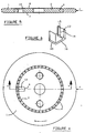
- FIG. 1 it consists of an outer ring 1 and an inner ring 2, arranged concentrically which define an annular space receiving rolling bodies 4 in contact with the raceways 5e, 5i carried by rings 1 and 2.
- the inner ring 2 is produced in the form of a disc receiving the conventional fixing members.
- the outer ring 1 is rotatably mounted and is subjected to a load F directed radially towards its axis of rotation.
- An axial notch 6 formed at the periphery of the ring 2 allows the rolling bodies 4 to be inserted between said rings 1,2.
- the bottom of the notch 6 is cylindrical as shown in FIG. 1 or plan according to variant of the bearing shown in FIG. 4.
- the notch 6 opens in contact with the opposite faces 7, 8 of the ring 2 and its dimensioning is such that the distance R1 from the bottom of the notch 6 to the axis of rotation of the ring 1 is less than the corresponding distance R2 from the raceway 5i carried by the ring 2.
- the notch 6 receives a shutter device 10.
- the shutter has a lower face 11 in contact with the notch 6 and an upper face 12 flexible.
- the flexibility of the face 12 allows the radial deformation of the device in contact with the rolling bodies 4 during the process of closing the notch.
- the upper face 12 also carries two ribs 13, 13 ′ of axial retention of the shutter which bear laterally on the rolling bodies, along which is formed an angular sector alpha of raceway 5i.
- the underside of the shutter 10 has a rib 14 engaged in a groove of the notch 6 in order to provide an additional means for axial retention of the shutter.
- the latter consists of two flexible elements 17, 17 ′ provided with mutual fastening means 18 shown diagrammatically in FIG. 3.
- This alternative embodiment allows the axial mounting of the elements 17, 17 ′ in contact with the 2 faces of the ring without noticeable radial deformation of one or the other element when these have ribs such as 13, 13 ′.
- the vertical face 18 of the shutter is located in the plane of the ring 2.
- the shutter has two axial wings 19, 20 among which the wing 19 defines the flexible upper face and carries the ribs 13, 13 ′ between which is locates the portion of the raceway 5i, while the wing 20 is in abutment on the bottom of the notch 6.
- the bearing may receive a cage with thin walls in which the rolling bodies are very close together.
Landscapes
- Engineering & Computer Science (AREA)
- General Engineering & Computer Science (AREA)
- Mechanical Engineering (AREA)
- Rolling Contact Bearings (AREA)
- Mounting Of Bearings Or Others (AREA)
- Structures Of Non-Positive Displacement Pumps (AREA)
Description
- L'invention concerne un palier ou roulement notamment à corps roulants jointifs conforme au préambule de la revendication 1.
- La publication FR-A-2279971 décrit un tel palier dans lequel un dispositif obturateur au contact des corps roulants possède une face inférieure au contact de l'encoche d'introduction des corps roulants et une face supérieure à flexibilité radiale.
- La publication FR-A-2339773 décrit un procédé d'assemblage d'un roulement à billes jointives entre une bague indéformable et une bague en matériau plastique déformable.
- Les procédés de montage des corps roulants et les roulements ainsi obtenus nécessitent des matières sélectionnées dont la déformation conditionne la fabrication correcte du roulement.
- La publication FR-A-346386 décrit un roulement dans lequel l'une des bagues possède une encoche de montage des corps roulants tandis que l'autre bague possède un orifice radial obturable qui augmente l'ouverture d'introduction. De tels moyens de montage sont inaplicables aux roulements minces ou aux roulements dont un chemin de roulement est porté par un disque plein.
- L'invention a pour objet de remédier aux inconvénients des roulements et procédés de montage connus et concerne plus particulièrement un palier ou roulement à corps roulants jointifs soumis à une charge radiale de direction sensiblement constante par rapport à la bague tournante.
- La caractéristique de la revendication 1 remédie aux inconvénients précités. Dans le roulement ainsi réalisé, il est possible de monter un plus grand nombre de corps roulants sans nécessiter une quelconque déformation des bagues.
- D'autres caractéristiques et avantages du roulement apparaitront à la lecture de la description de deux exemples de réalisation de celui-ci, faite en référence au dessin annexé dans lequel
- la figure 1 est une vue de face d'un roulement selon une première variante de réalisation de l'encoche de montage,
- la figure 2 est une vue en perspective du dispositif obturateur de l'encoche de montage du roulement représenté à la figure 1,
- la figure 3 est une vue en coupe d'une variante de réalisation du dispositif obturateur à partir de deux éléments flexibles munis de moyens d'accrochage mutuel,
- la figure 4 est une vue de face du roulement selon une deuxième variante de réalisation de l'encoche,
- la figure 5 est une vue en coupe radiale du roulement représenté à la figure 4 suivant la ligne V-V,
- la figure 6 est une vue en perspestive de l'obturateur flexible de l'encoche du roulement représenté à la figure 4.
- Dans un souci de simplification et de clarté on désignera dans ce qui suit les pièces homologues des roulements et dispositifs représentés sur les différentes figures par les mêmes références.
- Selon le mode de réalisation du roulement représenté à la figure 1, celui-ci est constitué par une bague extérieure 1 et par une bague intérieure 2, disposées concentriquement qui définissent un espace annulaire recevant des corps roulants 4 au contact de chemins de roulement 5e, 5i portés par les bagues 1 et 2.
- La bague intérieure 2 est réalisée sous la forme d'un disque recevant les organes de fixation conventionnels.
- La bague extérieure 1 est montée tournante et est soumise à une charge F dirigée radialement vers son axe de rotation.
- Une encoche 6 axiale pratiquée a la périphérie de la bague 2 permet l'introduction des corps roulants 4 entre les dites bagues 1,2.
- Le fond de l'encoche 6 est cylindrique comme représenté à la figure 1 ou plan selon variante du roulement représentée à la figure 4.
- Selon l'invention l'encoche 6 débouche au contact des faces opposées 7, 8 de la bague 2 et son dimensionnement est tel que la distance R1 du fond de l'encoche 6 a l'axe de rotation de la bague 1 est inférieure à la distance correspondante R2 du chemin de roulement 5i porté par la bague 2. .
- Selon une autre caractéristique de l'invention l'encoche 6 reçoit un dispositif obturateur 10.
- Selon les deux modes de réalisation du dispositif obturateur 10 représentés aux figures 2, 3, l'obturateur possède une face inférieure 11 en contact avec l'encoche 6 et une face supérieure 12 flexible. La flexibilité de la face 12 permet la déformation radiale du dispositif au contact des corps roulants 4 au cours du processus d'obturation de l'encoche.
- La face supérieure 12 porte par ailleurs deux nervures 13, 13′ de rétention axiale de l'obturateur qui prennent appui latéralement sur les corps roulants, le long desquelles est formé un secteur angulaire alpha de chemin de roulement 5i.
- Ainsi que cela est montré à la figure 3, la face inférieure de l'obturateur 10 possède une nervure 14 engagée dans une rainure de l'encoche 6 dans le but de réaliser un moyen additionnel de retenue axiale de l'obturateur.
- Selon une autre variante de réalisation de l'obturateur, ce dernier est constitué par deux éléments flexibles 17, 17′ munis de moyens d'accrochage mutuel 18 représentés schématiquement à la figure 3. Cette variante de réalisation permet le montage axial des éléments 17,17′ au contact des 2 faces de la bague sans déformation radiale notable de l'un ou l'autre élément lorsque ceux-ci comportent des nervures telles que 13, 13′.
- Selon le mode réalisation de l'obturateur représenté à la figure 6 celui-ci possède une configuration en C.
- La face verticale 18 de l'obturateur est située dans le plan de la bague 2. L'obturateur possède deux ailes axiales 19, 20 parmi lesquelles l'aile 19 définit la face supérieure flexible et porte les nervures 13, 13′ entre lesquelles se situe la portion du chemin de roulement 5i, tandis que l'aile 20 est en appui sur le fond de l'encoche 6.
- Sans sortir du cadre de l'invention, le roulement pourra recevoir une cage à parois minces dans laquelle les corps roulants sont très rapprochés.
Claims (6)
- Palier ou roulement notamment à corps roulants jointifs du type comportant une bague extérieure (1) et une bague intérieure (2) concentriques, munies respectivement de chemins de roulement (5i, 5e), une pluralité de corps roulants (4) déposés au contact desdits chemins ; dans lequel une encoche (6) axiale pratiquée dans l'une des bagues forme un chemin d'introduction des corps roulants (4) et débouche sur au moins une face axiale de la bague pour recevoir un dispositif obturateur (10) au contact des corps roulants (4) portant des moyens de rétention axiale (13, 13′) et dans lequel l'obturateur possède une face inférieure (11) au contact de l'encoche (6), caractérisé par le fait, que l'obturateur possède une face supérieure (12) à flexibilité radiale formant un secteur angulaire du chemin de roulement et que ladite face supérieure porte lesdits moyens (13, 13′) de rétention axiale de l'obturateur (10).
- Palier ou roulement selon la revendication 1, caractérisé par le fait que les moyens de rétention axiale de l'obturateur (10) sont constitués par deux nervures (13, 13′) en appui latéral sur les corps roulants (4), entre lesquelles est formé le secteur angulaire du chemin de roulement.
- Palier ou roulement selon l'une quelconque des revendications 1, 2, caractérisé par le fait que la face inférieure de l'obturateur (10) possède une nervure de retenue axiale (14) coopérant avec une rainure de l'encoche (6).
- Palier ou roulement selon l'une quelconque des revendications 1 à 3, caractérisé par le fait que l'obturateur (10) est constitué par deux éléments flexibles (17, 17′) à moyens d'accrochage mutuel.
- Palier ou roulement selon l'une quelconque des revendications 1 à 3 , caractérisé par le fait que l'obturateur (10) à une configuration en C dont une face verticale située dans le plan de la bague (2) possède deux ailes axiales (19, 20) dont l'une (19) peut être fléchie.
- Palier ou roulement selon la revendication 5, caractérisé par le fait que l'aile axiale flexible (19) de l'obturateur porte des nervures (13, 13′) latérales délimitant un secteur du chemin du roulement.
Applications Claiming Priority (2)
| Application Number | Priority Date | Filing Date | Title |
|---|---|---|---|
| FR9001056 | 1990-01-30 | ||
| FR9001056A FR2657663B1 (fr) | 1990-01-30 | 1990-01-30 | Palier ou roulement notamment a corps roulants jointifs. |
Publications (2)
| Publication Number | Publication Date |
|---|---|
| EP0439971A1 EP0439971A1 (fr) | 1991-08-07 |
| EP0439971B1 true EP0439971B1 (fr) | 1994-09-21 |
Family
ID=9393219
Family Applications (1)
| Application Number | Title | Priority Date | Filing Date |
|---|---|---|---|
| EP90403315A Expired - Lifetime EP0439971B1 (fr) | 1990-01-30 | 1990-11-23 | Palier ou roulement notamment à corps roulants jointifs |
Country Status (5)
| Country | Link |
|---|---|
| EP (1) | EP0439971B1 (fr) |
| JP (1) | JP2842949B2 (fr) |
| KR (1) | KR0183007B1 (fr) |
| DE (1) | DE69012782T2 (fr) |
| FR (1) | FR2657663B1 (fr) |
Families Citing this family (5)
| Publication number | Priority date | Publication date | Assignee | Title |
|---|---|---|---|---|
| DE112009005020T5 (de) * | 2009-07-02 | 2012-09-06 | Harmonic Drive Systems Inc. | Nicht-kreisförmiges Lager, Wellgenerator und Wellgetriebe |
| ITTO20110240A1 (it) * | 2011-03-18 | 2012-09-19 | Thiha Win | Bozzello |
| FR3022309B1 (fr) | 2014-06-11 | 2017-03-24 | Ntn-Snr Roulements | Roulement comportant une bague interieure en plusieurs parties, procede de montage d'un tel roulement et ensemble compose d'un tel roulement. |
| CN113357268A (zh) * | 2021-06-30 | 2021-09-07 | 瓦房店轴承集团国家轴承工程技术研究中心有限公司 | 带有定位结构的轴承外圈 |
| GB2624231A (en) * | 2022-11-11 | 2024-05-15 | Rigging Projects Ltd | Sheave assembly |
Family Cites Families (5)
| Publication number | Priority date | Publication date | Assignee | Title |
|---|---|---|---|---|
| US2530660A (en) * | 1946-07-26 | 1950-11-21 | Conveyor Systems | Bearing |
| US3606503A (en) * | 1968-11-14 | 1971-09-20 | Skf Svenska Kullagerfab Ab | Rolling bearing |
| FR2142793B1 (fr) * | 1971-06-25 | 1973-06-29 | Rks | |
| DE2435965C2 (de) * | 1974-07-26 | 1983-02-10 | Skf Kugellagerfabriken Gmbh, 8720 Schweinfurt | Wälzlager |
| DE3411562A1 (de) * | 1984-03-29 | 1985-10-10 | INA Wälzlager Schaeffler KG, 8522 Herzogenaurach | Drahtwaelzlager |
-
1990
- 1990-01-30 FR FR9001056A patent/FR2657663B1/fr not_active Expired - Fee Related
- 1990-11-23 DE DE69012782T patent/DE69012782T2/de not_active Expired - Fee Related
- 1990-11-23 EP EP90403315A patent/EP0439971B1/fr not_active Expired - Lifetime
- 1990-12-29 KR KR1019900022544A patent/KR0183007B1/ko not_active Expired - Fee Related
-
1991
- 1991-01-30 JP JP3029621A patent/JP2842949B2/ja not_active Expired - Fee Related
Also Published As
| Publication number | Publication date |
|---|---|
| EP0439971A1 (fr) | 1991-08-07 |
| KR910021546A (ko) | 1991-12-20 |
| KR0183007B1 (ko) | 1999-05-15 |
| JPH04211718A (ja) | 1992-08-03 |
| FR2657663B1 (fr) | 1995-01-20 |
| FR2657663A1 (fr) | 1991-08-02 |
| DE69012782D1 (de) | 1994-10-27 |
| DE69012782T2 (de) | 1995-04-27 |
| JP2842949B2 (ja) | 1999-01-06 |
Similar Documents
| Publication | Publication Date | Title |
|---|---|---|
| EP0495323B1 (fr) | Roulement à capteur d'informations | |
| EP0959258B1 (fr) | Agencement d'étanchéité pour un roulement | |
| EP0214065A1 (fr) | Prothèse de la hanche perfectionnée | |
| FR2508851A1 (fr) | Ensemble de palier pour la roue motrice d'un vehicule automobile | |
| FR2585420A1 (fr) | Roulement radial | |
| EP0956456A1 (fr) | Roulement et palier comportant un insert de compensation thermique | |
| FR2698137A1 (fr) | Palier, en particulier pour systèmes de débrayage d'embrayages à friction. | |
| FR2570146A1 (fr) | Dispositif d'etancheite pour roulement | |
| FR2664856A1 (fr) | Unite moyeu-joint homocinetique avec roulement de roue a deux rangees de corps roulants, et procede de fabrication d'une telle unite. | |
| FR2643693A1 (fr) | Roulement de butee pourvu d'un dispositif de positionnement et de maintien en place | |
| FR2669692A1 (fr) | Roulement double a contact oblique. | |
| EP0057348B1 (fr) | Palier à roulement à contact oblique à deux rangées d'éléments roulants et procédé de montage | |
| FR2711403A1 (fr) | Dispositif d'étanchéité pour passage de fluide à travers un roulement, et roulement équipé d'un tel dispositif. | |
| FR2581140A1 (fr) | Palier pour mouvement lineaire axial | |
| FR2610543A1 (fr) | Tete a disposition angulaire pour centrifugeuses | |
| EP0439971A1 (fr) | Palier ou roulement notamment à corps roulants jointifs | |
| FR2755734A1 (fr) | Roulement a charge radiale avec une cage retenue par des rebords de la bague exterieure | |
| FR2621364A1 (fr) | Roulement sans arbre central, a deux rangees d'elements roulants cylindriques | |
| FR2551816A1 (fr) | Cage pour dispositif de roue libre a galets de blocage | |
| FR2551513A1 (fr) | Roulement a billes pour le montage a deplacement longitudinal d'arbres ou analogues | |
| WO2022161735A1 (fr) | Roulement de roue equipe d'un dispositif d'etancheite a gouttiere et chicane | |
| FR2571105A1 (fr) | Fixation pour solidarisation en rotation d'un composant mecanique | |
| FR2601735A1 (fr) | Dispositif de roue libre a cames du type a autocentrage a paliers | |
| EP0677686A1 (fr) | Boîtier porte-joint d'étanchéité à palier de guidage et son application notamment à une automobile | |
| FR2600131A1 (fr) | Roulement a rouleaux comportant une cage intercalaire de retention radiale et axiale des rouleaux |
Legal Events
| Date | Code | Title | Description |
|---|---|---|---|
| PUAI | Public reference made under article 153(3) epc to a published international application that has entered the european phase |
Free format text: ORIGINAL CODE: 0009012 |
|
| AK | Designated contracting states |
Kind code of ref document: A1 Designated state(s): BE CH DE GB IT LI SE |
|
| 17P | Request for examination filed |
Effective date: 19920114 |
|
| 17Q | First examination report despatched |
Effective date: 19930524 |
|
| GRAA | (expected) grant |
Free format text: ORIGINAL CODE: 0009210 |
|
| AK | Designated contracting states |
Kind code of ref document: B1 Designated state(s): BE CH DE GB IT LI SE |
|
| ITF | It: translation for a ep patent filed | ||
| GBT | Gb: translation of ep patent filed (gb section 77(6)(a)/1977) |
Effective date: 19940928 |
|
| REF | Corresponds to: |
Ref document number: 69012782 Country of ref document: DE Date of ref document: 19941027 |
|
| EAL | Se: european patent in force in sweden |
Ref document number: 90403315.6 |
|
| PLBE | No opposition filed within time limit |
Free format text: ORIGINAL CODE: 0009261 |
|
| STAA | Information on the status of an ep patent application or granted ep patent |
Free format text: STATUS: NO OPPOSITION FILED WITHIN TIME LIMIT |
|
| 26N | No opposition filed | ||
| PGFP | Annual fee paid to national office [announced via postgrant information from national office to epo] |
Ref country code: SE Payment date: 20001030 Year of fee payment: 11 |
|
| PG25 | Lapsed in a contracting state [announced via postgrant information from national office to epo] |
Ref country code: SE Free format text: LAPSE BECAUSE OF NON-PAYMENT OF DUE FEES Effective date: 20011124 |
|
| REG | Reference to a national code |
Ref country code: GB Ref legal event code: IF02 |
|
| EUG | Se: european patent has lapsed |
Ref document number: 90403315.6 |
|
| PGFP | Annual fee paid to national office [announced via postgrant information from national office to epo] |
Ref country code: DE Payment date: 20041105 Year of fee payment: 15 |
|
| PGFP | Annual fee paid to national office [announced via postgrant information from national office to epo] |
Ref country code: CH Payment date: 20041109 Year of fee payment: 15 |
|
| PGFP | Annual fee paid to national office [announced via postgrant information from national office to epo] |
Ref country code: GB Payment date: 20041122 Year of fee payment: 15 |
|
| PGFP | Annual fee paid to national office [announced via postgrant information from national office to epo] |
Ref country code: BE Payment date: 20041201 Year of fee payment: 15 |
|
| PG25 | Lapsed in a contracting state [announced via postgrant information from national office to epo] |
Ref country code: IT Free format text: LAPSE BECAUSE OF NON-PAYMENT OF DUE FEES;WARNING: LAPSES OF ITALIAN PATENTS WITH EFFECTIVE DATE BEFORE 2007 MAY HAVE OCCURRED AT ANY TIME BEFORE 2007. THE CORRECT EFFECTIVE DATE MAY BE DIFFERENT FROM THE ONE RECORDED. Effective date: 20051123 Ref country code: GB Free format text: LAPSE BECAUSE OF NON-PAYMENT OF DUE FEES Effective date: 20051123 |
|
| PG25 | Lapsed in a contracting state [announced via postgrant information from national office to epo] |
Ref country code: LI Free format text: LAPSE BECAUSE OF NON-PAYMENT OF DUE FEES Effective date: 20051130 Ref country code: CH Free format text: LAPSE BECAUSE OF NON-PAYMENT OF DUE FEES Effective date: 20051130 Ref country code: BE Free format text: LAPSE BECAUSE OF NON-PAYMENT OF DUE FEES Effective date: 20051130 |
|
| PG25 | Lapsed in a contracting state [announced via postgrant information from national office to epo] |
Ref country code: DE Free format text: LAPSE BECAUSE OF NON-PAYMENT OF DUE FEES Effective date: 20060601 |
|
| REG | Reference to a national code |
Ref country code: CH Ref legal event code: PL |
|
| GBPC | Gb: european patent ceased through non-payment of renewal fee |
Effective date: 20051123 |
|
| BERE | Be: lapsed |
Owner name: *S.N.R. ROULEMENTS Effective date: 20051130 |