EP0439685B1 - Buchsenlager - Google Patents
Buchsenlager Download PDFInfo
- Publication number
- EP0439685B1 EP0439685B1 EP90120217A EP90120217A EP0439685B1 EP 0439685 B1 EP0439685 B1 EP 0439685B1 EP 90120217 A EP90120217 A EP 90120217A EP 90120217 A EP90120217 A EP 90120217A EP 0439685 B1 EP0439685 B1 EP 0439685B1
- Authority
- EP
- European Patent Office
- Prior art keywords
- bush
- spring element
- bearing according
- outer bush
- bush bearing
- Prior art date
- Legal status (The legal status is an assumption and is not a legal conclusion. Google has not performed a legal analysis and makes no representation as to the accuracy of the status listed.)
- Expired - Lifetime
Links
Images


Classifications
-
- F—MECHANICAL ENGINEERING; LIGHTING; HEATING; WEAPONS; BLASTING
- F16—ENGINEERING ELEMENTS AND UNITS; GENERAL MEASURES FOR PRODUCING AND MAINTAINING EFFECTIVE FUNCTIONING OF MACHINES OR INSTALLATIONS; THERMAL INSULATION IN GENERAL
- F16F—SPRINGS; SHOCK-ABSORBERS; MEANS FOR DAMPING VIBRATION
- F16F3/00—Spring units consisting of several springs, e.g. for obtaining a desired spring characteristic
- F16F3/08—Spring units consisting of several springs, e.g. for obtaining a desired spring characteristic with springs made of a material having high internal friction, e.g. rubber
- F16F3/10—Spring units consisting of several springs, e.g. for obtaining a desired spring characteristic with springs made of a material having high internal friction, e.g. rubber combined with springs made of steel or other material having low internal friction
- F16F3/12—Spring units consisting of several springs, e.g. for obtaining a desired spring characteristic with springs made of a material having high internal friction, e.g. rubber combined with springs made of steel or other material having low internal friction the steel spring being in contact with the rubber spring
-
- F—MECHANICAL ENGINEERING; LIGHTING; HEATING; WEAPONS; BLASTING
- F16—ENGINEERING ELEMENTS AND UNITS; GENERAL MEASURES FOR PRODUCING AND MAINTAINING EFFECTIVE FUNCTIONING OF MACHINES OR INSTALLATIONS; THERMAL INSULATION IN GENERAL
- F16F—SPRINGS; SHOCK-ABSORBERS; MEANS FOR DAMPING VIBRATION
- F16F1/00—Springs
- F16F1/36—Springs made of rubber or other material having high internal friction, e.g. thermoplastic elastomers
- F16F1/366—Springs made of rubber or other material having high internal friction, e.g. thermoplastic elastomers made of fibre-reinforced plastics, i.e. characterised by their special construction from such materials
-
- F—MECHANICAL ENGINEERING; LIGHTING; HEATING; WEAPONS; BLASTING
- F16—ENGINEERING ELEMENTS AND UNITS; GENERAL MEASURES FOR PRODUCING AND MAINTAINING EFFECTIVE FUNCTIONING OF MACHINES OR INSTALLATIONS; THERMAL INSULATION IN GENERAL
- F16F—SPRINGS; SHOCK-ABSORBERS; MEANS FOR DAMPING VIBRATION
- F16F1/00—Springs
- F16F1/36—Springs made of rubber or other material having high internal friction, e.g. thermoplastic elastomers
- F16F1/373—Springs made of rubber or other material having high internal friction, e.g. thermoplastic elastomers characterised by having a particular shape
Definitions
- the invention relates to a bush bearing, in particular for motor vehicles, with a cylindrical outer bush and an internal, elastic support of a bearing bolt, wherein an annular body is arranged within the outer bush, which is elastically coupled to the outer bush in a discrete circumferential area and one via a Has rubber liner coupled to the annular body inner sleeve for receiving the bearing pin.
- Such a bearing bush is known from FR-A-2 555 688.
- three cylindrical metal bushes arranged concentrically to one another are provided, which are connected to one another and are supported against one another over a respective partial region of the circumference and offset with respect to one another.
- Such bush bearings as well as bush bearings, which are known for example from DE-C-2 755 117, serve to dampen vibrations and minimize noise transmission.
- they have the disadvantage that the static deflection increases with the loading time as a result of the rubber being set, and that the acoustic insulation effect deteriorates if the pressure stops intervene prematurely.
- rubber has a dynamic hardening, so that with increasing frequency there is an increasing dynamic stiffness of the bearing and thus a more favorable transmission of high-frequency transmission Vibrations results.
- EP-A-0 324 693 it is known from EP-A-0 324 693 to form the essentially load-bearing elements of an elastic support bearing from an annular spring body made of fiber-reinforced plastic, whereby spring elements can be created, the optimal spring properties without static setting and without dynamic hardening.
- the present invention is therefore an object of the invention to provide a bush bearing that can be used using such spring elements made of fiber-reinforced plastic for vibration-isolating mounting of drive units and as a maintenance-free bearing to compensate for oscillating movements with small path or angle amplitudes.
- the annular body is designed as a spring body, consists of fiber-reinforced plastic and, based on the peripheral region of the elastic coupling of the spring body to the outer bush, has the rubber intermediate layer in the opposite peripheral region.
- the annular spring body has an oval or elliptical cross section, so that different spring hardnesses can be achieved in the vertical and transverse directions. It is also expedient if, in such a bearing, the inner bushing consists of a U-shaped bracket which extends with its base part extending between the two free legs in the axial direction of the annular spring body and has bores in its free legs for receiving the bearing pin.
- the U-shaped bracket When such a bush bearing is loaded essentially in the direction of pressure, the U-shaped bracket is expediently arranged on the outside of the spring body and, with its free legs, engages around the spring body laterally and radially inwards.
- the U-shaped bracket can be arranged on the inside of the spring body with legs directed radially inwards.
- the spring body can be arranged coaxially to the outer bush or also transversely to the outer bush.
- the annular spring body is formed from two separate individual springs running parallel and at a distance from one another, and the U-shaped bracket is a base part which extends transversely across the two individual springs and has two narrower springs which are located in the space between the two individual springs extending legs.
- a holding plate is vulcanized on by means of an intermediate rubber layer, which is rigidly connected to the outer sleeve.
- a bridge-shaped bracket can be provided on the inside of the outer bush, which is screwed to the spring body holder.
- an elastic stop cushion which extends at least to close to the outer bushing, is vulcanized on the outside of the spring body.
- rubber pads can be provided opposite one another within the spring body as pressure stops.
- the one pressure stop can be formed by a rubber cushion that at least fills the free space between the radially projecting legs of the U-shaped bracket.
- stop strips in the form of circular sections can be arranged on opposite end edges of the outer bushing on both sides of the stop cushion.
- the spring body is installed in the outer bush in the prestressed state by correspondingly oversizing one of the elastic stop pads.
- a cylindrical outer sleeve 1 made of metal and coaxial with this an oval spring body 2 made of fiber-reinforced plastic.
- This spring body 2 consists of a winding body made of several concentric winding layers of fibers running in the circumferential direction of the winding body and transverse to the direction of loading and at least one layer of fibers running at an angle to the other layers.
- a metal holding plate 4 is vulcanized via a rubber intermediate layer 3, which is rigidly fastened against a bridge-shaped bracket 5 on the inside of the outer bush 2 by means of a screw 6.
- a U-shaped bracket 7 encompassing the spring body 2 is vulcanized on the opposite side via a corresponding rubber intermediate layer 8, the two free legs 9 and 10 of the bracket 7 encompassing the spring body 2 laterally and radially inward are directed. In these free legs 9 and 10 bores 11 and 12 are then provided for receiving the bearing pin.
- an arched rubber stop pad is provided on the outside, which is supported on the inner wall of the outer bush 1 in the relieved state shown.
- the stop pad 17 filling the entire free space between the legs 9 and 10 of the bracket 7 and extending further, this rubber pad 17 having a corresponding recess 18 between the has two holes 11 and 12 for the bearing pin.
- the bush bearing shown is essentially loaded in the direction of pressure and can be installed in the pretensioned state, for which purpose the upper stop pad has a greater height than is required to bridge the gap between the top of the ring spring 2 and the outer bush 1.
- an S-shaped spring characteristic can be achieved, which results in a low static and dynamic rigidity at the working point and a progressive behavior in the tensile and compressive range outside the working point.
- angular stops 20 and 21 are used on both sides of the stop pad on the inside of the outer sleeve 2.
- circular section-shaped stop strips 22 and 23 can then additionally be arranged on the opposite end edges of the outer socket 1 on both sides of the stop cushion 15, as can be seen in particular from FIG. 2.
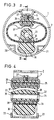
- FIGS. 3 and 4 A bush bearing in which the internal spring body is essentially stressed in tension is shown in FIGS. 3 and 4.
- an oval or elliptical spring body 2 is arranged inside the outer bush 1 and coaxially with it. This is now enclosed for coupling to the outer bush by a ring 25 enclosing the spring body 2, which is connected to the spring body 2 via a rubber intermediate layer 26 and is likewise fixed to the bridge-shaped bracket 5 on the inside of the outer bush via a screw connection 27.
- a U-shaped bracket 30 is arranged, which is also connected to the spring body 2 via a rubber intermediate layer 31 and whose side legs 32 and 33 protrude radially inwards with corresponding bores 34 and 35 for receiving the bearing bolt.
- a stop pad 36 is also provided to limit movement relative to the outer bush in the pulling direction.
- Opposing pads 37 and 38 are also integrated within the spring body 2, which come into engagement under corresponding pressure loads.
- Such a bush bearing can also be preloaded in such a way that when the stop pads 37 and 38 are vulcanized in, the spring body 2 is stretched in the pulling direction and a larger stop pad is vulcanized in than corresponds to the free space with the spring body 2 relaxed.
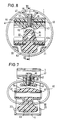
- the spring body consists of two separate individual springs 40 and 41 running parallel to one another and at a distance from one another, which are connected to one another on the coupling side to the outer bushing 1 via two metallic webs 42 and 43 and intermediate rubber layers 44 and via a spacer sleeve 45 between the two webs 42 and 43 penetrating screw 46 are fixed on the bridge-shaped bracket 47 on the inside of the outer sleeve.
- a U-shaped bracket 50 with a base part 51 extending across both individual springs 40 and 41 and two narrower, in the space between the two individual springs 40 and 41 extending legs 52 and 53 with the receiving bores 54 and 55 for the bearing bolt also vulcanized via a rubber layer 56.
- a stop cushion 57 is provided on the outside of the bracket 50 and corresponding stop cushion 58 between the bracket legs 52 and 53 and a stop cushion 59 are provided within the spring bodies 40 and 41.
- FIGS. 7 and 8 With a transverse installation of the spring body and a load in the pulling direction, a construction according to FIGS. 7 and 8 is possible.
- a corresponding U-shaped bracket 60 with its two narrower legs 61 and 62 is arranged on the inside of the two individual springs 40 and 41 and is also fixed relative to the latter by means of a rubber intermediate layer 62 and the stop cushion 63 projecting outwards.
Landscapes
- Engineering & Computer Science (AREA)
- General Engineering & Computer Science (AREA)
- Mechanical Engineering (AREA)
- Springs (AREA)
- Vibration Prevention Devices (AREA)
- Support Of The Bearing (AREA)
Applications Claiming Priority (2)
| Application Number | Priority Date | Filing Date | Title |
|---|---|---|---|
| DE3938383 | 1989-11-18 | ||
| DE3938383A DE3938383C1 (ja) | 1989-11-18 | 1989-11-18 |
Publications (2)
| Publication Number | Publication Date |
|---|---|
| EP0439685A1 EP0439685A1 (de) | 1991-08-07 |
| EP0439685B1 true EP0439685B1 (de) | 1993-09-15 |
Family
ID=6393799
Family Applications (1)
| Application Number | Title | Priority Date | Filing Date |
|---|---|---|---|
| EP90120217A Expired - Lifetime EP0439685B1 (de) | 1989-11-18 | 1990-10-22 | Buchsenlager |
Country Status (4)
| Country | Link |
|---|---|
| EP (1) | EP0439685B1 (ja) |
| JP (1) | JPH03172636A (ja) |
| DE (2) | DE3938383C1 (ja) |
| ES (1) | ES2043217T3 (ja) |
Families Citing this family (9)
| Publication number | Priority date | Publication date | Assignee | Title |
|---|---|---|---|---|
| DE4035728A1 (de) * | 1990-11-09 | 1992-05-14 | Bayerische Motoren Werke Ag | Elastisches lager fuer eine abgasanlage eines kraftfahrzeugs |
| DE4106838A1 (de) * | 1991-03-04 | 1992-09-10 | Metzeler Gimetall Ag | Daempfendes aggregatlager |
| GB2337314B (en) * | 1996-06-17 | 2000-01-12 | R & D Marine Ltd | Improvements in or relating to rotary damping couplings |
| JPH11218185A (ja) * | 1998-02-03 | 1999-08-10 | Kurashiki Kako Co Ltd | 防振マウント |
| JP4753670B2 (ja) * | 2005-09-06 | 2011-08-24 | 倉敷化工株式会社 | ブッシュ |
| US20090039574A1 (en) * | 2007-08-10 | 2009-02-12 | Paul William Cook | Spring assembly |
| DE102007041324B4 (de) * | 2007-08-31 | 2019-05-23 | Volkswagen Ag | Gummimetalllager |
| US9848709B2 (en) * | 2015-06-04 | 2017-12-26 | Donald J. Molenda | Multi layered modular support system for lounge and other applications |
| RU207299U1 (ru) * | 2021-05-05 | 2021-10-21 | Акционерное общество "Научно-производственный центр "Полюс" | Комбинированный демпфер |
Family Cites Families (5)
| Publication number | Priority date | Publication date | Assignee | Title |
|---|---|---|---|---|
| DE2755117C2 (de) * | 1977-12-10 | 1985-01-31 | Metzeler Kautschuk GmbH, 8000 München | Vorspannbares Lagerelement |
| IT1161640B (it) * | 1983-03-11 | 1987-03-18 | Pirelli | Unita' di sopporto atta a sopportare elasticamente una massa e a smorzarne le vibrazioni |
| FR2555688B1 (fr) * | 1983-11-25 | 1988-03-18 | Ouest Cie | Support elastique a faible raideur, notamment pour vehicule automobile |
| FR2631668B2 (fr) * | 1988-01-15 | 1993-11-12 | Hutchinson | Supports elastiques de suspension |
| DE3908474A1 (de) * | 1988-07-22 | 1990-01-25 | Metzeler Gmbh | Ringfoermiger federkoerper aus faserverbundwerkstoffen |
-
1989
- 1989-11-18 DE DE3938383A patent/DE3938383C1/de not_active Expired - Fee Related
-
1990
- 1990-10-22 EP EP90120217A patent/EP0439685B1/de not_active Expired - Lifetime
- 1990-10-22 DE DE90120217T patent/DE59002749D1/de not_active Expired - Fee Related
- 1990-10-22 ES ES90120217T patent/ES2043217T3/es not_active Expired - Lifetime
- 1990-11-13 JP JP2304188A patent/JPH03172636A/ja active Pending
Also Published As
| Publication number | Publication date |
|---|---|
| ES2043217T3 (es) | 1993-12-16 |
| DE3938383C1 (ja) | 1990-11-22 |
| JPH03172636A (ja) | 1991-07-26 |
| DE59002749D1 (de) | 1993-10-21 |
| EP0439685A1 (de) | 1991-08-07 |
Similar Documents
| Publication | Publication Date | Title |
|---|---|---|
| EP0183197B1 (de) | Elastisches Motorlager | |
| DE102008014941B4 (de) | Karosserie/Rahmen-Montageanordnung, Kraftfahrzeug sowie Verfahren zur Dämpfung von Betriebsbelastungen bei einem Karosseriebauteil | |
| WO2013091671A1 (de) | Schwingungsgedämpftes möbel in der form eines tisches | |
| EP0439685B1 (de) | Buchsenlager | |
| DE112013004246T5 (de) | Zylindrische Schwingungsdämpfungsvorrichtung | |
| EP0363563B1 (de) | Gummilager | |
| DE19731128A1 (de) | Pendelstütze für ein Aggregat in einem Kraftfahrzeug und elastisches Aggregatelager | |
| DE10142822A1 (de) | Innentilger | |
| EP2165864B1 (de) | Einrichtung zum Befestigen einer Stange eines Feder-Dämpfer-Systems | |
| EP0230685B1 (de) | Befestigung des Stossdämpfers in einer Waschmaschine | |
| DE102015002278B4 (de) | Getriebelager-Anordnung für ein Kraftfahrzeug | |
| DE102017215403B4 (de) | Federbaugruppe | |
| EP1426647A1 (de) | Tragarm und Verfahren zu dessen Herstellung | |
| WO2020126284A1 (de) | Elastomerlager zur anbringung eines aggregats im fahrzeug | |
| DE102007058207B3 (de) | Fahrzeugsitz, insbesondere Kraftfahrzeugsitz | |
| EP0670233A2 (de) | Aufhängung bewegter Bauteile bei Kraftfahrzeugen | |
| WO2000014428A1 (de) | Stoss- und schwingungsdämpfer, insbesondere zur aufhängung von abgasanlagen von kraftfahrzeugen | |
| DE3921968A1 (de) | Schalldaemmeinrichtung | |
| EP1580448B1 (de) | Schwingungsdämpfende Lagerung eines Bauteiles | |
| EP0351737B1 (de) | Hydraulisch dämpfendes Motorlager | |
| EP2796743B1 (de) | Elastisches Lager | |
| DE102018205737B4 (de) | Aggregatelagerung für ein Antriebsaggregat eines Fahrzeugs | |
| DE102016208023A1 (de) | Bauteil zur Anwendung in Zug- und/oder Druckbelastung | |
| DE10317082A1 (de) | Aktiver Feder-Dämpfungsmechanismus | |
| DE102021119470A1 (de) | Lagerbuchse, Lagerbuchsenanordnung und Windenergieanlagenlager für Windenergieanlagen |
Legal Events
| Date | Code | Title | Description |
|---|---|---|---|
| PUAI | Public reference made under article 153(3) epc to a published international application that has entered the european phase |
Free format text: ORIGINAL CODE: 0009012 |
|
| 17P | Request for examination filed |
Effective date: 19901022 |
|
| AK | Designated contracting states |
Kind code of ref document: A1 Designated state(s): DE ES FR GB IT SE |
|
| 17Q | First examination report despatched |
Effective date: 19920818 |
|
| GRAA | (expected) grant |
Free format text: ORIGINAL CODE: 0009210 |
|
| AK | Designated contracting states |
Kind code of ref document: B1 Designated state(s): DE ES FR GB IT SE |
|
| REF | Corresponds to: |
Ref document number: 59002749 Country of ref document: DE Date of ref document: 19931021 |
|
| GBT | Gb: translation of ep patent filed (gb section 77(6)(a)/1977) |
Effective date: 19930928 |
|
| ITF | It: translation for a ep patent filed |
Owner name: ING. C. GREGORJ S.P.A. |
|
| REG | Reference to a national code |
Ref country code: ES Ref legal event code: FG2A Ref document number: 2043217 Country of ref document: ES Kind code of ref document: T3 |
|
| ET | Fr: translation filed | ||
| PLBE | No opposition filed within time limit |
Free format text: ORIGINAL CODE: 0009261 |
|
| STAA | Information on the status of an ep patent application or granted ep patent |
Free format text: STATUS: NO OPPOSITION FILED WITHIN TIME LIMIT |
|
| 26N | No opposition filed | ||
| PGFP | Annual fee paid to national office [announced via postgrant information from national office to epo] |
Ref country code: FR Payment date: 19941011 Year of fee payment: 5 |
|
| PGFP | Annual fee paid to national office [announced via postgrant information from national office to epo] |
Ref country code: GB Payment date: 19941012 Year of fee payment: 5 |
|
| PGFP | Annual fee paid to national office [announced via postgrant information from national office to epo] |
Ref country code: SE Payment date: 19941017 Year of fee payment: 5 |
|
| PGFP | Annual fee paid to national office [announced via postgrant information from national office to epo] |
Ref country code: DE Payment date: 19941021 Year of fee payment: 5 |
|
| PGFP | Annual fee paid to national office [announced via postgrant information from national office to epo] |
Ref country code: ES Payment date: 19941031 Year of fee payment: 5 |
|
| EAL | Se: european patent in force in sweden |
Ref document number: 90120217.6 |
|
| PG25 | Lapsed in a contracting state [announced via postgrant information from national office to epo] |
Ref country code: GB Effective date: 19951022 |
|
| PG25 | Lapsed in a contracting state [announced via postgrant information from national office to epo] |
Ref country code: SE Effective date: 19951023 Ref country code: ES Free format text: LAPSE BECAUSE OF THE APPLICANT RENOUNCES Effective date: 19951023 |
|
| GBPC | Gb: european patent ceased through non-payment of renewal fee |
Effective date: 19951022 |
|
| PG25 | Lapsed in a contracting state [announced via postgrant information from national office to epo] |
Ref country code: FR Effective date: 19960628 |
|
| EUG | Se: european patent has lapsed |
Ref document number: 90120217.6 |
|
| PG25 | Lapsed in a contracting state [announced via postgrant information from national office to epo] |
Ref country code: DE Effective date: 19960702 |
|
| REG | Reference to a national code |
Ref country code: FR Ref legal event code: ST |
|
| REG | Reference to a national code |
Ref country code: ES Ref legal event code: FD2A Effective date: 19991007 |
|
| PG25 | Lapsed in a contracting state [announced via postgrant information from national office to epo] |
Ref country code: IT Free format text: LAPSE BECAUSE OF NON-PAYMENT OF DUE FEES;WARNING: LAPSES OF ITALIAN PATENTS WITH EFFECTIVE DATE BEFORE 2007 MAY HAVE OCCURRED AT ANY TIME BEFORE 2007. THE CORRECT EFFECTIVE DATE MAY BE DIFFERENT FROM THE ONE RECORDED. Effective date: 20051022 |