EP0439613B1 - Container loading/unloading vehicle - Google Patents
Container loading/unloading vehicle Download PDFInfo
- Publication number
- EP0439613B1 EP0439613B1 EP89913184A EP89913184A EP0439613B1 EP 0439613 B1 EP0439613 B1 EP 0439613B1 EP 89913184 A EP89913184 A EP 89913184A EP 89913184 A EP89913184 A EP 89913184A EP 0439613 B1 EP0439613 B1 EP 0439613B1
- Authority
- EP
- European Patent Office
- Prior art keywords
- carrier
- container
- connecting member
- bottom connecting
- side bottom
- Prior art date
- Legal status (The legal status is an assumption and is not a legal conclusion. Google has not performed a legal analysis and makes no representation as to the accuracy of the status listed.)
- Expired - Lifetime
Links
- 230000033001 locomotion Effects 0.000 claims abstract description 17
- 230000008878 coupling Effects 0.000 claims description 33
- 238000010168 coupling process Methods 0.000 claims description 33
- 238000005859 coupling reaction Methods 0.000 claims description 33
- 238000013459 approach Methods 0.000 claims description 11
- 238000000926 separation method Methods 0.000 claims description 4
- 230000001174 ascending effect Effects 0.000 claims description 3
- 230000005540 biological transmission Effects 0.000 abstract description 5
- 239000012530 fluid Substances 0.000 description 32
- 230000007935 neutral effect Effects 0.000 description 12
- 229910000831 Steel Inorganic materials 0.000 description 8
- 239000010959 steel Substances 0.000 description 8
- 238000000034 method Methods 0.000 description 6
- 230000001360 synchronised effect Effects 0.000 description 4
- 239000007788 liquid Substances 0.000 description 3
- 230000008602 contraction Effects 0.000 description 2
- 230000003014 reinforcing effect Effects 0.000 description 2
- 238000005516 engineering process Methods 0.000 description 1
- 230000000284 resting effect Effects 0.000 description 1
- 239000002699 waste material Substances 0.000 description 1
Images












Classifications
-
- B—PERFORMING OPERATIONS; TRANSPORTING
- B65—CONVEYING; PACKING; STORING; HANDLING THIN OR FILAMENTARY MATERIAL
- B65D—CONTAINERS FOR STORAGE OR TRANSPORT OF ARTICLES OR MATERIALS, e.g. BAGS, BARRELS, BOTTLES, BOXES, CANS, CARTONS, CRATES, DRUMS, JARS, TANKS, HOPPERS, FORWARDING CONTAINERS; ACCESSORIES, CLOSURES, OR FITTINGS THEREFOR; PACKAGING ELEMENTS; PACKAGES
- B65D90/00—Component parts, details or accessories for large containers
- B65D90/0033—Lifting means forming part of the container
-
- B—PERFORMING OPERATIONS; TRANSPORTING
- B60—VEHICLES IN GENERAL
- B60P—VEHICLES ADAPTED FOR LOAD TRANSPORTATION OR TO TRANSPORT, TO CARRY, OR TO COMPRISE SPECIAL LOADS OR OBJECTS
- B60P1/00—Vehicles predominantly for transporting loads and modified to facilitate loading, consolidating the load, or unloading
- B60P1/64—Vehicles predominantly for transporting loads and modified to facilitate loading, consolidating the load, or unloading the load supporting or containing element being readily removable
- B60P1/6418—Vehicles predominantly for transporting loads and modified to facilitate loading, consolidating the load, or unloading the load supporting or containing element being readily removable the load-transporting element being a container or similar
- B60P1/6427—Vehicles predominantly for transporting loads and modified to facilitate loading, consolidating the load, or unloading the load supporting or containing element being readily removable the load-transporting element being a container or similar the load-transporting element being shifted horizontally in a fore and aft direction, combined or not with a vertical displacement
-
- B—PERFORMING OPERATIONS; TRANSPORTING
- B65—CONVEYING; PACKING; STORING; HANDLING THIN OR FILAMENTARY MATERIAL
- B65D—CONTAINERS FOR STORAGE OR TRANSPORT OF ARTICLES OR MATERIALS, e.g. BAGS, BARRELS, BOTTLES, BOXES, CANS, CARTONS, CRATES, DRUMS, JARS, TANKS, HOPPERS, FORWARDING CONTAINERS; ACCESSORIES, CLOSURES, OR FITTINGS THEREFOR; PACKAGING ELEMENTS; PACKAGES
- B65D90/00—Component parts, details or accessories for large containers
- B65D90/12—Supports
- B65D90/14—Legs, e.g. detachable
-
- B—PERFORMING OPERATIONS; TRANSPORTING
- B65—CONVEYING; PACKING; STORING; HANDLING THIN OR FILAMENTARY MATERIAL
- B65D—CONTAINERS FOR STORAGE OR TRANSPORT OF ARTICLES OR MATERIALS, e.g. BAGS, BARRELS, BOTTLES, BOXES, CANS, CARTONS, CRATES, DRUMS, JARS, TANKS, HOPPERS, FORWARDING CONTAINERS; ACCESSORIES, CLOSURES, OR FITTINGS THEREFOR; PACKAGING ELEMENTS; PACKAGES
- B65D90/00—Component parts, details or accessories for large containers
- B65D90/12—Supports
- B65D90/18—Castors, rolls, or the like; e.g. detachable
Definitions
- the present invention relates to a container carrier and a container which can be loaded and unloaded from the carrier according to the preamble part of claim 1 and 3.
- Such a container and container carrier are known from DE-B-2 041 574.
- This container carrier comprises a articulated loading arm provided on the carrier body, and a container provided on the top front an engaging member which catches on a hook on the end of the loading arm.
- the hook on the end of the loading arm engages the engaging member on the front of the container, and lifts the container up onto the body at an angle.
- the container is unloaded, it is similarly lowered at an angle from the carrier to the ground by the loading arm.
- the container is diagonal to the horizontal when it is loaded and unloaded from a conventional container carrier as thus described, it cannot be loaded with such articles as pianos, furniture, fragile objects and breakables, tanks containing liquids, and similar goods.
- Such containers are therefore in practice limited to use with rubbish and other waste materials.
- the first object of the present invention is to provide a container carrier and a container which can be loaded and unloaded from the carrier while retaining a level attitude, and can therefore be used for the transportation of pianos, furniture, breakables, tanks containing liquids, and similar goods.
- a second object of the present invention is to provide a container carrier and a container which can be loaded and unloaded from the carrier while retaining a horizontal attitude, and in addition can prevent the container from bouncing up from the carrier when bumps and holes in the road are hit during transportation, and is thus able to prevent damage to the container and the carrier, and so enables the driver to relax while driving.
- a third object of the present invention is to provide a container carrier from which a container can be loaded and unloaded while retaining a level attitude, and which enables the container to automatically engage and disengage with the carrier.
- a fourth object of the present invention is to provide a container carrier from which a container can be loaded and unloaded while retaining a level attitude, and which can prevent operational errors, can prevent the container from sloping even if the operator does err in operation, and therefore prevents the cargo inside the container from falling over.
- a roller at the bottom end of the support member, or a ground member which contacts the ground and is unmovable.
- the container When the container is loaded on the carrier, it is possible to synchronize the front and back of the container body so that the container remains level by raising the front of the container by lifting the top connecting member at the front of the container body by means of the member of the carrier, and holding the bottom connecting member at the front of the container fixed with respect to the ground, transferring the motion of the bottom connecting member relative to the container body to the support member at the back of the container by means of the transmitting means, and extending the support member at the back of the container down to raise the back of the container.
- the container When the container is raised to approximately the same height as the bed of the carrier, the container can be advanced forward onto the carrier by pulling forward, for example, on the couple while supporting the back of the container with the support member on the ground. After this, the support member can be lifted from the ground by operating a bottom connecting member, for example, by a means on the carrier side.
- the support member may also be folded and secured so that it is not supporting the container against the ground.
- the frame size can be enlarged to the maximum limit possible when there are restrictions on the outside dimensions of the container body.
- the container capacity can be increased to the maximum limit.
- the container When the container is loaded on the carrier, it is possible to synchronize the front and back of the container body so that the container remains level by raising the front of the container via the top connecting member by means of the top connecting member on the carrier, and holding the bottom connecting member at the front of the container fixed with respect to the ground by means of the carrier-side bottom connecting member, transferring the motion of the container-side bottom connecting member relative to the container body to the support member at the back of the container by means of the transmitting means, and extending the support member at the back of the container down to raise the back of the container.
- the container When the container is raised to approximately the same height as the bed of the truck, the container can be advanced forward onto the carrier by pulling forward, for example, on the couple while supporting the back of the container with the support member on the ground.
- the support member can be lifted from the ground by operating, for example, the bottom connecting member on the container and carrier by a bottom connecting member drive means on the carrier side.
- a level posture can still be maintained by simply reversing the procedure just described.
- the container when the container is lifted to the same height as the vehicle, the container can also be loaded onto the vehicle by backing the vehicle up instead of pulling forward on the couple.
- a container carrier is characterized in that an engaging member having a pin is provided at the center or rear part of one of the container or the carrier, and in the other of the container or the carrier is provided a guide member; this guide member comprises a tapered guide portion, which is provided to guide the pin of the engaging member and raise the carrier body so that the bottom of the container connects with the top of the carrier body when the container is loaded horizontally with an even gap to the carrier, and a horizontal contact portion, which is formed in contact with the guide portion and which contacts the pin of the engaging member when the container is loaded completely onto the carrier.
- the pin in the engaging member will be in contact with the contact portion of the guide portion.
- the center or rear parts of the container and carrier are coupled together by the guide members and engaging member.
- the front of the container is coupled firmly to the carrier by the top connecting members on the carrier and container and by the bottom connecting members on the carrier and container. The container is therefore coupled at both front and back to the carrier.
- the container carrier according to the present invention is characterized in that the carrier-side bottom connecting member comprises a holding member with a U-shaped portion which can accept the engaging member of the container-side bottom connecting member , and a closing member which can close an opening of the U-shaped portion when the engaging member is enclosed in the holding member, and an operating mechanism which cause the closing member to open or close the opening of the U-shaped portion in connection with the approach or separation of the carrier-side top connecting member to the carrier-side bottom connecting member.
- the operating mechanism causes the closing member to open the opening of the U-shaped portion of the holding member in connection with the action of the two connecting members meeting.
- the engaging member of the container-side bottom connecting member easily couples with and separates from the U-shaped portion of the holding member of the carrier-side bottom connecting member.
- the operating mechanism causes the closing member to close the opening of the U-shaped portion of the holding member in connection with the action of the two connecting members separating.
- the closing member is a connecting pin
- the above operating mechanism releases the connection of the holding member and the engaging member with the connecting pin in conjunction with the descending action of the carrier-side top connecting member as it approaches the carrier-side bottom connecting member when the carrier-side bottom connecting member is at the lowest position in the column device, and connects the holding member and the engaging member with the connecting pin in conjunction with the ascending action of the carrier-side top connecting member as it separates from the carrier-side bottom connecting member when the carrier-side bottom connecting member is at the lowest position in the column device.
- the above operating mechanism comprises a spring member, a roller, and a bell crank on the carrier-side bottom connecting member with first, second, and third arms, wherein the first arm of the bell crank is mounted on the connecting pin, the spring member constantly applies pressure to the second arm of the bell crank, and applies an operating force to the first arm in the direction causing the connecting pin to connect the holding member and the engaging member, and the roller, mounted on the third arm of the bell crank, moves the first arm of the bell crank in the direction which causes the coupling of the holding member and the engaging member to be released by contacting a pressure plate provided at the carrier-side top connecting member when the carrier-side top connecting member approaches the carrier-side bottom connecting member; and when the carrier-side top connecting member separates from the carrier-side bottom connecting member, it separates from the pressure plate and permits the connecting pin to connect the holding member and the engaging member.
- the above operating mechanism comprises an arm provided on the carrier-side bottom connecting member, a spring member, and an operating pin; one end of the arm is mounted on the carrier-side bottom connecting member so that it can rotate freely, and the other end is connected to the connecting pin; the spring member applies constant pressure to the other end of the arm in the direction causing the connecting pin to couple the holding member and the engaging member; and the operating pin is mounted vertically with the bottom end at the approximate center of the arm; when the carrier-side top connecting member descends and approaches the carrier-side bottom connecting member, the bottom of the carrier-side top connecting member contacts the operating pin, and the aforementioned other end of the arm is moved in the direction causing the coupling of the holding member and the engaging member to be released; when the carrier-side top connecting member separates from the carrier-side bottom connecting member, the operating pin separates from the bottom of the carrier-side top connecting member and is permitted to couple the holding member and the engaging member.
- the carrier-side bottom connecting member comprises a holding member with a U-shaped portion which accepts the engaging member of the container-side bottom connecting member; a lock member provided at the opening of the U-shaped portion and pivoting on the holding member so as to rotate freely to enable coupling and decoupling of the engaging member with the U-shaped portion of the holding member; and a rotating member which pivots on the holding member, rotates up and down in conjunction with the contact and separation of the carrier-side top connecting member, and when the rotating member is in an engaging position with the lock member, holds the coupling of the engaging member in the U-shaped portion of the holding member with the lock member.
- the carrier-side bottom connecting member When the carrier-side bottom connecting member is in the down position in the column device, and the carrier-side top connecting member descends and contacts the carrier-side bottom connecting member, the bottom of the carrier-side top connecting member presses against the rotating member, causing it to rotate down and causing the lock member to open the U-shaped portion.
- the engaging member of the container-side bottom connecting member easily couples with or separates from the U-shaped portion of the holding member of the carrier-side bottom connecting member.
- the carrier-side bottom connecting member when the carrier-side bottom connecting member is in the down position in the column device, and the carrier-side top connecting member rises and separates from the bottom connecting member, the bottom of the top connecting member separates from the rotating member, stopping the rotating member in the engaging position and thereby holding the engaging member in the U-shaped portion.
- the carrier comprises a column drive mechanism which moves the column device forward and back
- the speed can be controlled and the container can be moved levelly by driving the column drive mechanism.
- a roller is provided on the bottom of the support member of the container
- the container is moved levelly on the container carrier with the carrier brakes applied and the carrier stopped.
- the transmission of the carrier is set in neutral, the column drive mechanism is operated to move the carrier levelly to the ground so that the container is thus moved horizontally relative to the body.
- the carrier comprises a carrier-side bottom connecting member drive means which moves the carrier-side bottom connecting member vertically
- the container support member can be raised from the ground by operating the carrier-side bottom connecting member drive means after the container is loaded on the carrier.
- the container carrier comprises a column device provided to move forward and back on a subframe mounted on a chassis frame, a carrier-side top connecting member provided on the column device so that it moves vertically and can couple with a container-side top connecting member, a carrier-side bottom connecting member provided on the column device so that it moves vertically and can couple with the container-side bottom connecting member, a lift chain, one end of which is fixed to the carrier-side top connecting member and the other end of which is connected to the column device, a lift sprocket to an upper side of which is wound the lift chain, a first fluid cylinder which raises and lowers the lift sprocket by the extension and contraction of a piston rod, and a second fluid cylinder which raises and lowers the carrier-side bottom connecting member by the extension and contraction of a piston rod, lines which connect the first fluid cylinder and the second fluid cylinder in parallel, a single control valve which switches the flow of fluid in the direction causing the first fluid cylinder and the
- the container is loaded as follows.
- the retraction and extension of the first and second fluid cylinders respectively cause the carrier-side top connecting member to descend and the carrier-side bottom connecting member to descend.
- the column device is located at the back of the vehicle, and when the container-side top connecting member and the carrier-side top connecting member, and the container-side bottom connecting member and the carrier-side bottom connecting member are each connected to the other, the control valve is first operated to switch the fluid flow so that the first and second fluid cylinders simultaneously extend. This causes the front of the container to be lifted by the carrier-side top connecting member via the lift chain and the lift sprocket, while the back of the container is lifted by the extension of the support member so that the container is lifted while retaining a level attitude.
- the control valve is operated to change the fluid flow in the direction causing the first and second fluid cylinders to simultaneously retract.
- the first fluid cylinder is constrained by the subchain via the subsprocket and held in the extended position, and the lift chain cannot disengage from the lift sprocket.
- the second fluid cylinder is not constrained and retracts, and the support member at the back of the container is stored inside the rear column.
- the container carrier comprises a column device provided to move a subframe mounted on a chassis frame forward and back, a carrier-side top connecting member provided on the column device so that the carrier-side top connecting member moves vertically and can couple with a container-side top connecting member, a carrier-side bottom connecting member provided on the column device so that the carrier-side bottom connecting member moves vertically and can couple with a container-side bottom connecting member, drive means which raise and lower the carrier-side top connecting member and the carrier-side bottom connecting member; a limit switch which operates when the column device is positioned on the subframe at the back; and an operating switch which enables the operation of the drive means only when the limit switch operates.
- the limit switch When the column device is positioned at the back of the subframe, the limit switch operates. Therefore, by operating the operating switch connected to this limit switch, the drive means can be operated. Specifically, when the column device is positioned at the back of the subframe, the carrier-side top connecting member moves up or down, the carrier-side bottom connecting member remains stationary relative to the ground, and the container remains level when ascending and descending.
- the limit switch does not operate.
- the drive means will therefore not operate even if a worker mistakenly operates the operating switch while the container is moving horizontally.
- the carrier-side top connecting member and the carrier-side bottom connecting member will therefore not move vertically, and the front and back of the container will be maintained at the same height. Tilting of the container is thus prevented, and the contents of the container will also not fall over.
- FIG. 1 and Fig. 2 show the container 1 and carrier 45 according to a first embodiment of the present invention.
- the container 1 comprises a box-shaped container body 2, pillar-shaped support members 3, a top connecting member 11 on the container, a bottom connecting member 16 on the container, and chains 21, 40 as transmitting members.
- the container body 2 is composed of symmetrical pillar-shaped rear columns 5, front columns 13, side columns 30 (shown only on one side), rear beam 4, front beam 14, top side frames 10, bottom side frames 9, front panel 12, bottom panel 19, legs 20, and top and side panels not shown in the figure.
- a channel 12a with a U-shaped cross section running vertically is provided at the center of the front panel 12 and the front beam 14.
- the support members 3 fit inside the rear columns 5 so that they can be raised and lowered freely, and are each provided with a roller 7 mounted on the bottom end by way of a bracket 6.
- the bottoms of these support members 3 are connected by a single shaft 8, which causes both support members 3 to ascend and descend in unison.
- the top connecting member 11 of the container is a semicircular member the ends of which are attached on a horizontal line at the upper center of the front panel 12.
- the container-side bottom connecting member 16 comprises a key-shaped engaging member 17, which has a rectangular plate 17a and a ring 17b, and a channel-shaped sliding member 18; the bottom connecting member 16 is constructed in such a way that the rectangular plate 17a and the bottom of the channel in the sliding member 18 intersect.
- a pair of guides 15 formed from channel steel are provided inside the channel 12a of the front beam 14 and front panel 12 with the channels facing inside and parallel to one another with a gap in between; the rectangular plate 17a of the engaging member 17 is fit into this gap, and the outside surface of the guides 15 slides in contact with the inside surface of the channel in sliding member 18.
- the complete bottom connecting member 16 can thereby slide up and down.
- a pair of chains 21 is provided symmetrically (shown only on one side in the figure) with one end connected to the side of the sliding member 18, the chain passing through the front beam 14 and mounted on a pair of sprockets 23, 24 to carry the chain first horizontally from the up vertical and then down vertically from the horizontal, through the front column 13, around the sprocket 25 at the bottom of the front column 13 so that the chain is carried from the vertical horizontally to the back through the bottom side frame 9, around the sprocket 26 at the back end of the bottom side frame 9 from the lengthwise horizontal to the vertical, and the other end is connected to the top 3a of the support member 3.
- the other chain 40 likewise has one end connected to the bottom of the engaging member 17, is passed vertically at the front of the container body 2, guided from the vertical to the horizontal lengthwise by the sprocket 42 provided at the front bottom of the container body 2, under the bottom panel 19, guided vertically by the sprocket 43 provided at the back bottom of the container body 2, and the other end is connected to the shaft 8.
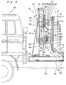
- Fig. 2 shows the carrier 45.
- This carrier 45 is provided with channelled subframes 47 parallel and with the channels facing the inside on the chassis frame 46.
- the column device 51 is provided on the subframes 47 so that it can move freely back and forth in the direction indicated by arrow X.
- This column device 51 is such that it can slide along the top of the subframes 47 on its slide pads 52, which sandwich the top rails of the subframes 47.
- the column device 51 also comprises a pair of columns 55 made of H-channel steel; the tops of the columns 55 are connected by horizontal plate 70, and the bottoms are connected by a bottom plate not shown in the figure.
- This bottom plate is connected to the pair of chains 58 which turn around the two pairs of sprockets 56, 57 provided at the front and back of the chassis.
- a sprocket 60 is provided on the shaft connecting the rear sprockets 57, and is driven by a hydraulic motor 59. Therefore, this hydraulic motor 59 moves the column device 51 forward and back in the direction of arrow X by driving the chains 58.
- a carrier-side top connecting member 61 and a carrier-side bottom connecting member 91 are also provided at the back of the columns 55 in such a way that they can move freely up and down, respectively, as indicated by arrow Z.
- the carrier-side top connecting member 61 comprises a pair of plates 62 with an L-shaped cross section connected by a horizontal rod 66, a holding member 63 mounted on the vertical rod 67, a coupling pin 65 which passes through and connects both sides of the holding member 63, a pair of right and left arms 68 and operating pins 69, and pressure plate 100 mounted on the plates 62.
- the holding member 63 is provided horizontally with the U-shaped portion 63c formed by the top part 63a and the bottom part 63b facing the back. Studs 67a, 65a, and 69a are provided horizontally, respectively, at the top of the vertical rod 67, coupling pin 65, and operating pins 69.
- a round hole is provided in one end and oval holes are provided at the other end and at approximately the center of the arms 68; the arms 68 are mounted with one end rotating freely on the studs 67a, and the oval holes at the other end and the approximate center rotating freely and with play in the long direction on the studs 65a and 69a.
- the weight of the coupling pin 65 causes the arms 68 to rotate down pivoting on the studs 67a, thus connecting the part 63a, 63b of the holding member 63, and when the operating pins 69 are driven up by the rod 92, the lever action lifts the coupling pin 65 up from the holding member 63.
- the carrier-side top connecting member 61 is constructed such that it can travel vertically between the right and left columns 55 along the inside of the channel in the columns 55 guided by the rollers 64 and 64a mounted at the side of the plates 62.
- the carrier-side bottom connecting member 91 comprises a pair of side plates 97 covering the sides of the columns 55; a pair of rods 92, 93 top and bottom connecting the side plates 97 horizontally; holding member 95 at the center of the rods 92, 93; a connecting pin 96 which can connect both sides of the holding member 95; a stud 76b which rotates freely in brackets 77 provided at the top of the rod 92; a bell crank 76 composed of arm 76a, arm 76c and arm 76d which are formed as a single assembly with the stud 76b; coil spring 98 as the reflexive member; and rollers 99 at the end of the third arm 76d. It is to be noted that the bell crank 76, coil spring 98, and rollers 99 form an operating mechanism, and that the rollers 99 can contact the pressure plate 100 of the carrier-side top connecting member 61.
- the holding member 95 is provided with the U-shaped portion 95c formed by left part 95a and the right part 95b horizontal and facing the back.
- the bell crank 76 is mounted with the first arm 76a and the second arm 76c facing in opposite directions around the stud 76b, and the third arm 76d approximately perpendicular to the arms 76a and 76c.
- a stud 96a is provided horizontally at one end of the connecting pin 96, an oval hole is provided in the end of the first arm 76a, and the end of the first arm 76a is mounted so as to rotate freely on the stud 96a.
- the carrier-side bottom connecting member 91 is able to travel up and down along the outside channel in the right and left columns 55 on the rollers 94, 94a provided inside the side plates 97.
- the pressure plate 100 of the carrier-side top connecting member 61 pushes the rollers 99 of the carrier-side bottom connecting member 91 down, and the rod 92 of the carrier-side bottom connecting member 91 presses the operating pins 69 of the carrier-side top connecting member 61; when the carrier-side top connecting member 61 and the carrier-side bottom connecting member 91 separate vertically, the pressure plate 100 and rollers 99, rod 92 and operating pins 69 each separate.
- a right and left pair of hydraulic cylinders 71 is mounted inside the pair of columns 55 with the piston rods 71a pointing down, the top sprockets 82 mounted to the top ends of the tubes 71b of the hydraulic cylinders 71, and the bottom sprockets 86 mounted to the bottom end of the tubes 71b.
- One end of the top chain 84 is mounted to the top 87 of the plates 62, the top chain 84 is mounted on the top sprocket 82 so that it descends vertically, and the other end is fixed to the mounting point 81 of the bridge 53 connecting the pair of columns 55 horizontally.
- the bottom chain 85 one end of which is fixed to the bottom 88 of the plates 62, is mounted on the bottom sprocket 86 and the other end is fixed to the mounting point 81 of the bridge 53.
- the carrier-side bottom connecting member 91 is connected to the piston rods 71a of the hydraulic cylinders 71 by a nut 72, thus causing the bottom connecting member 91 to be driven up and down according to the action of the piston rods 71a.
- the carrier-side top connecting member 61 and the carrier-side bottom connecting member 91 are vertically proximal only when they are both at the lowest position (hereinafter the down position) in the columns 55, and when either one is at any position other than the down position, they are separated from each other according to the length of the tubes 71b and the piston rods 71a.
- the container 1 and carrier 45 as described above operate as follows.
- the carrier 45 and the container 1 are positioned as shown in Fig. 5 (a) at the start of the loading operation with the container-side bottom connecting member 16 in the up position and the support members 3 retracted inside the rear columns 5.
- the carrier-side top connecting member 61 and the carrier-side bottom connecting member 91 are both in the down position in the column device 51, and the holding members 63, 95 are therefore released.
- the U-shaped portion 63c of the holding member 63 of the carrier-side top connecting member 61 couples with the top connecting member 11, and the ring 17b of the engaging member 17 on the container-side bottom connecting member 16 couples with the U-shaped portion 95c of the holding member 95 in the carrier-side bottom connecting member 91.
- the holding member 63 and holding member 95 are both automatically closed by the coupling pins 65, 96, respectively, and the carrier-side top connecting member 61 and the container-side top connecting member 11, and the carrier-side bottom connecting member 91 and the container-side bottom connecting member 16 are thus automatically coupled together.
- Fig. 5 (b) the front of the container 1 is lifted via the container-side top connecting member 11 by the carrier-side top connecting member 61, and at the same time the back of the container 1 is lifted by the support members 3 as described below.
- the hydraulic cylinders 71 are retracted with the container 1 mounted on the carrier 45 as shown in Fig. 6.
- the carrier-side top connecting member 61 is held at the height of the container-side top connecting member 11 because it is coupled thereto.
- the hydraulic tubes 71b are constrained vertically by the bottom chain 85 and the top chain 84, and are held at the same height. Therefore, as shown in Fig. 4 (c), the end of the piston rods 71a separate from the seat 48 of the chassis frame 46 and rises, and the carrier-side bottom connecting member 91 connected to the end of the piston rods 71a is thereby lifted.
- the container-side bottom connecting member 16 coupled to the carrier-side bottom connecting member 91 is lifted, and the support members 3 are raised from the ground via the chain 21 and the chain 40.
- a container carrier according to the first embodiment of the present invention can load and unload a container 1 to the carrier 45 while holding the container 1 in a level position. Moreover, the carrier-side top connecting member 61 and container-side top connecting member 11, and the carrier-side bottom connecting member 91 and the container-side bottom connecting member 16 are automatically coupled and released with the loading and unloading action, and it is thereby possible to prevent any damage caused by the container dropping during loading and unloading.
- this container 1 passes the chain 21 used as the transmitting means through the bottom side frames 9 of the container body 2, and the support members 3 are fit inside the rear columns 5, when the outside dimensions of the container body 2 are restricted, the frame size can be increased to the maximum allowable, and the cargo volume can be maximized.
- the chain 21 is protected by the bottom side frames 9, which are structural members of the container body 2, separate members to protect the chain are not necessary.
- FIG. 7 and Fig. 8 A second embodiment of the container 201 and the carrier 245 are shown in Fig. 7 and Fig. 8 wherein those parts which are the same as in the first embodiment are shown with like numbers.
- the container 201 has a container-side bottom connecting member 216.
- the container-side bottom connecting member 216 comprises a engaging member 117 and a sliding member 118.
- the engaging member 117 is composed of a rectangular plate 117e perpendicular to the horizontal rectangular plate 117b with reinforcing ribs 117d bridging therebetween, and a vertical rectangular plate 117a perpendicular to the rectangular plate 117e.
- a round hole 117c is provided in the rectangular plate 117b so that a connecting pin 196 can pass therethrough.
- Said container-side bottom connecting member 216 is constructed in such a way that the rectangular plate 117a and the bottom of the channel in the sliding member 118 intersect.
- a pair of guides 15 formed from channel steel are provided inside the channel 12a of the front beam 14 and front panel 12 with the channels of the guides facing inside and parallel to one another with a gap therebetween; the rectangular plate 117a of the engaging member 117 is fit into this gap, and the inside surface of the channel in sliding member 118 slides in contact with the outside surface of the guides 15.
- Fig. 8 shows the carrier 245.
- This carrier 245 comprises a column device 51 as in the first embodiment described hereinabove, with the carrier-side top connecting member 61 and the carrier-side bottom connecting member 291 each provided so as to move freely up and down in the direction indicated by the arrow Z behind the columns 55.
- the carrier-side top connecting member 61 is constructed identically to that shown in the first embodiment.
- the holding member 63 has projecting members 63d which can contact the operating pin 200 of the carrier-side bottom connecting member 291 as will be described hereinbelow.
- the carrier-side bottom connecting member 291 comprises a pair of side plates 97 covering the sides of the columns 55; a pair of rods 92, 93 top and bottom connecting the side plates 97 horizontally; holding member 195 at the center of the rods 92, 93; a connecting pin 196 which can connect both sides of the holding member 195; a pair of left and right brackets 177 at the bottom of the rod 93; arms 176; operating pins 200 which can contact the projecting members 63d of the holding member 63; and coil springs 198 as the reflexive members. It is to be noted that the arms 176, operating pins 200, and coil springs 198 form the operating mechanism.
- the holding member 195 is provided with the U-shaped portion 195c formed by top part 195a and bottom part 195b horizontally and facing the back.
- the brackets 177, connecting pin 196, and operating pins 200 are each provided on the bottom end with horizontal studs 177a, 196a, and 200a, respectively; a round hole is provided in one end and oval holes are provided at the other end and at approximately the center of the arms 176.
- One end of the arms 176 is mounted so as to rotate freely on the studs 177a, and the oval holes at the other end and the approximate center rotating freely and with play in the long direction on the studs 196a, and 200a.
- the studs 196a and the bottom part 195b of the holding member 195 are connected by the coil springs 198, which constantly apply a force driving the connecting pin 196 in the direction through both sides of the holding member 195 (in Fig. 9 (a), the arms 176 rotating to the left on the studs 177a).
- the connecting pin 196 is driven up by the force of the coil springs 198, thereby connecting the top and bottom parts 195a, 195b on both sides of the holding member 195 and closing the couple; when the operating pins 200 are not forced downward by the projecting parts 63d, a lever action drives the holding member 195 down to open and release the couple.
- This carrier-side bottom connecting member 291 is constructed such that it can travel vertically along the outside channel in the right and left columns 55 on the rollers 94, 94a provided inside the side plates 97.
- the projecting parts 63d of the holding member 63 in the carrier-side top connecting member 61 pushes the operating pins 200 of the carrier-side bottom connecting member 291 downward
- the rod 92 of the carrier-side bottom connecting member 291 pushes on the operating pins 69 of the carrier-side top connecting member 61;
- the projecting parts 63d and the operating pins 200, and the rod 92 and the operating pins 69 each separate respectively.
- a pair of right and left hydraulic cylinders 71 is mounted inside the pair of columns 55 with the piston rods 71a pointing down, the top sprockets 82 mounted to the top ends of the tubes 71b of the hydraulic cylinders 71, and the bottom sprockets 86 mounted to the bottom ends of the tubes 71b.
- One end of the top chain 84 is mounted to the top 87 of the plates 62, the top chain 84 is mounted on the top sprocket 82 so that it descends vertically, and the other end is fixed to the mounting point 81 of the bridge 53 connecting the pair of columns 55 horizontally.
- the bottom chain 85 one end of which is fixed to the bottom 88 of the plates 62, is mounted on the bottom sprocket 86 and the other end is fixed to the mounting point 81 of the bridge 53.
- the carrier-side top connecting member 61 and the carrier-side bottom connecting member 291 are vertically proximal only when they are both at the lowest position (hereinafter the down position) in the columns 55, and when either one is at any position other than the down position, they are separated from each other according to the length of the tubes 71b and the piston rods 71a.
- the couplings of the holding member 63 and the holding member 195 are released by the action of the projecting parts 63d and operating pins 200, and the action of the rod 92 and the operating pins 69.
- the holding member 63 and the holding member 195 are each closed by the coupling pin 65 and the connecting pin 196, respectively.
- the container 201 and carrier 245 as described above operate as follows.
- the carrier 245 and the container 201 are positioned as shown in Fig. 5 (a) at the start of the loading operation with the bottom connecting member 216 in the up position and the support members 3 retracted inside the rear columns 5.
- the carrier-side top connecting member 61 and the carrier-side bottom connecting member 291 are both in the down position in the column device 51, and the holding members 63, 195 are therefore released.
- the U-shaped portion 63c of the holding member 63 of the carrier-side top connecting member 61 couples with the top connecting member 11 on the container, and the rectangular plate 117b of the engaging member 117 on the container-side bottom connecting member 216 couples with the U-shaped portion 195c of the holding member 195 in the carrier-side bottom connecting member 291.
- the holding member 63 and holding member 195 are both automatically closed by the coupling pins 65, 196, respectively, and the carrier-side top connecting member 61 and the container-side top connecting member 11, and the carrier-side bottom connecting member 291 and the container-side bottom connecting member 216 are thus automatically coupled together.
- the front of the container 201 is lifted via the container-side top connecting member 11 by the carrier-side top connecting member 61, and at the same time the back of the container 201 is lifted by the support members 3 as described below.
- the container-side bottom connecting member 216 is held stationary with respect to the ground by the carrier-side bottom connecting member 291
- the container-side bottom connecting member 216 descends relative to the container body 2.
- This action drives the chains 21 and 40, causing the support members 3 to extend down, thus lifting the back of the container 201.
- the front of the container 201 is lifted by the container-side top connecting member 11, and the back is lifted by the support members 3, this action is synchronized, and the container 201 thus remains level as it is raised as shown in Fig. 5 (b).
- the hydraulic cylinders 71 are retracted with the container 201 mounted on the carrier 245 as shown in Fig. 11.
- the carrier-side top connecting member 61 is held at the height of the container-side top connecting member 11 because it is coupled thereto.
- the hydraulic tubes 71b are constrained vertically by the bottom chain 85 and the top chain 84, and are held at the same height. Therefore, as shown in Fig. 10 (c), the end of the piston rods, 71a separate from the seat 48 of the chassis frame 46 and rises, and the carrier-side bottom connecting member 291 connected to the end of the piston rods 71a is thereby lifted.
- the container-side bottom connecting member 216 coupled to the carrier-side bottom connecting member 291 is lifted, and the support members 3 are raised from the ground via the chain 21 and the chain 40.
- a container carrier can load and unload a container 201 to the carrier 245 while holding the container 201 in a level position. Moreover, the carrier-side top connecting member 61 and container-side top connecting member 11, and the carrier-side bottom connecting member 291 and the container-side bottom connecting member 216 are automatically coupled and released with the loading and unloading action, and it is thereby possible to prevent any damage caused by the container dropping during loading and unloading.
- the carrier-side top connecting member 61 and the container-side top connecting member 11, and the carrier-side bottom connecting member 91 or 291 and the container-side bottom connecting member 16 or 216 are each automatically coupled and decoupled, but the present invention shall not be thus limited as the carrier-side top connecting member 61 and container-side top connecting member 11 may also be manually coupled and decoupled.
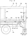
- Fig. 12 and Fig. 13 show the container 301 and carrier 345 according to a third embodiment of the present invention.
- the container 301 comprises a box-shaped container body 302, symmetrical pillar-shaped support members 303 as shown in Fig. 13, and as shown in Fig. 12 a top connecting member 311 on the container, a bottom connecting member 316 on the container, and chains 321, 340 as transmitting members.
- the container body 302 is composed of symmetrical pillar-shaped rear columns 305, front columns 313, side columns 330, top side frames 310, bottom side frames 309, horizontal girders 331, main girders 332, legs 320, and beams and covering panels not shown in the figures.
- the support members 303 fit inside the rear columns 305 so that they can be raised and lowered freely, and are each provided with a roller 307 mounted on the bottom end by way of a bracket 306.
- the bottoms of these right and left support members 303 are connected by a single shaft 308, which causes both support members 303 to ascend and descend in unison.
- the top connecting member 311 of the container is a semicircular shaped member, and is attached horizontally at the upper center of the container body 302.
- the container-side bottom connecting member 316 consists of an engaging member 317, formed by a semicircular member 317b attached horizontally to a perpendicular rectangular plate 317a, and a channelled sliding member 318; the rectangular plate 317a of the engaging member 317 is assembled to the outside surface of the channel bottom of the sliding member 318.
- the container-side bottom connecting member 316 complete is able to slide vertically along the guides 315 provided at the front center of the container body 302.
- a pair of chains 321 is provided (shown on only one side in the figure); one end of each chain is attached to the sliding member 318, and the chains 321 are led up and around a sprocket to the horizontal, from which they are mounted to sprockets 324, 325, and 326, which conduct the chain down, horizontally along the length, and then up, and the other end of the chains 321 is connected to the stud 303a of the support members 303.
- the other chain 340 likewise has one end connected to the bottom of the engaging member 317, is passed vertically at the front of the container body 302, guided from the vertical to the horizontal lengthwise by the sprocket 342 provided at the front bottom of the container body 302, around the sprocket 433 provided at the back bottom of the container body 2, and the other end is connected to the shaft 308.
- the carrier 345 is provided with channelled subframes 347 parallel and with the channels facing the inside on the chassis frame 346.
- the column device 351 is provided on the subframes 347 so that it can move freely back and forth.
- the column device 351 also comprises a pair of columns 355 made of H-channel steel; the tops of the columns 355 are connected by horizontal plate 370, and the bottoms are connected by a bottom plate 352.
- This bottom plate 352 is connected to the pair of chains 353 which turn around the two pairs of sprockets provided on the right and left sides at the front and back of the chassis, and the shaft connecting the back sprockets is driven by means of a hydraulic motor not shown in the figure. Therefore, by driving this chain 353 by means of the hydraulic motor, the column device 351 can be moved freely along the length of the body.
- a carrier-side top connecting member 361 and a carrier-side bottom connecting member 391 are also provided at the back of the columns 355 in such a way that they can move freely up and down.
- the carrier-side top connecting member 361 comprises a pair of plates 362 with an L-shaped cross section connected by a horizontal rod 366, a holding member 363 mounted on the vertical rod 367 which is connected to the center of the horizontal rod 366 in T-shape, a coupling pin 365 which passes through and connects both sides of the holding member 363, arm 368 and operating pin 369.
- the holding member 363 is provided horizontally with the U-shaped portion 363c formed by the top part 363a and the bottom part 363b facing the back.
- the bottom part 363b of the holding member 363 forces the connecting plate 409, described hereinbelow, of the carrier-side bottom connecting member 391 down when the carrier-side top connecting member 361 and the carrier-side bottom connecting member 391 are vertically proximal.
- Studs 367a, 365a, and 369a are provided horizontally, respectively, at the top of the vertical rod 367, coupling pin 365, and operating pins 369.
- a round hole is provided in one end and oval holes are provided at the other end and at approximately the center of the arm 368; the arm 368 is mounted with one end rotating freely on the studs 67a, and the oval holes at the other end and the approximate center rotating freely and with play in the long direction on the studs 365a and 369a.
- the carrier-side top connecting member 361 is constructed such that it can travel vertically between the right and left columns 355 along the inside of the channel in the columns 355 guided by rollers mounted at both the sides of the plates 362 but not shown in the figures.
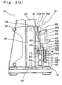
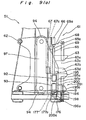
- Fig. 14 and Fig. 15 show the carrier-side bottom connecting member 391 from the top and back, respectively, and Fig. 16 shows the cross section at line IV-IV in Fig. 15.
- the carrier-side bottom connecting member 391 comprises a pair of side plates 397 covering the sides of the columns 355; a pair of sliding members 399 attached to the side plates 397 via the connecting rods 398; a pair of rods 392, 393 top and bottom connecting the side plates 397 horizontally; and a holding member 395 at the center of the rods 392, 393.
- a pair of rotating members 403, a twist spring 404 as the reflexive member, and a pair of locking members 405 mounted to the holding member 395.
- the holding member 95 is provided with a U-shaped portion 395c formed by top part 395a and bottom part 395b, and is mounted between the connecting rods 392, 393 with the U-shaped portion 395c horizontal and projecting out.
- the locking members 405 are long, narrow members comprising a straight side 405a and curved side 405b.
- the locking members 405 are mounted on stud 408, which passes horizontally through the top part 395a of the holding member 395 near the end, and are secured to the stud 408 by nuts 408a on both ends.
- the locking members 405 are able to rotate freely around the stud 408; when the locking members 405 are hanging perpendicularly of their own weight with the straight side 405a facing the connecting rod 392, at least part of the U-shaped portion 395c of the holding member 395 is closed.
- the rotating members 403 are approximately L-shaped members comprising a contact face 403a on the outside where the member bends in an L, and a contact face 403b at the end of the short leg of the L. These rotating members 403 are mounted on the ends of a stud 407, which passes horizontally through a point near the connecting rod 392 in the top part 395a of the holding member 395, and are secured by nuts 407a.
- a connecting plate 409 connecting the long legs of both rotating members 403 is provided so that the rotating members 403 turn around the stud 407 together.
- the rotating members 403 are also driven continuously around to the right by the force of the twist spring 404 as shown in Fig. 16.
- the rotating members 403 are turned around to the right by the action of the twist spring 404, the contact face 403b contacts the side 392a of the connecting rod 392 as an engaging part, and the clamp is stopped and coupled in the position shown in B in Fig. 16 (hereinafter the coupled position).
- the contact face 403b contacts the straight side 405a of the locking members 405 at a point up from the stud 408. At this time, the locking members 405 are allowed to rotate to the right towards the position A in Fig.
- the carrier-side bottom connecting member is able to move up and down along the outside channels in the right and left columns 355 on the sliding members 399 provided inside the side plates 397.
- a pair of right and left hydraulic cylinders 371 is mounted inside the pair of columns 355 with the piston rods 371a pointing down, the top ends of the tubes 371b of the hydraulic cylinders 371 mounted to the top sprocket 382, and the bottom end of the tubes 371b mounted to the bottom sprocket 386.
- One end of the top chain 384 is mounted to the top 387 of the plates 362, the top chain 384 is mounted on the top sprocket 382 so that it descends vertically, and the other end is fixed to the mounting point 381 of the bridge 353 connecting the pair of columns 355 horizontally.
- the bottom chain 385 one end of which is fixed to the bottom 388 of the plates 362, is mounted on the bottom sprocket 386 and the other end is fixed to the mounting point 381 of the bridge 353.
- the carrier-side bottom connecting member 391 is connected to the piston rods 371a of the hydraulic cylinders 371 by a nut 372, thus causing the bottom connecting member 391 to be driven up and down according to the action of the piston rods 371a.
- the carrier-side top connecting member 361 and the carrier-side bottom connecting member 391 are vertically proximal only when they are both at the lowest position (hereinafter the down position) in the columns 355 as shown in Fig. 17 (a), and when either one is at any position other than the down position as shown in Fig. 17 (b) and (c), they are separated from each other according to the length of the tubes 371b and the piston rods 371a.
- This container carrier is also provided with a guide portion 335 comprising a tapered guide portion 501 at the bottom back of the container body 302, and a horizontal contact part 502 which is connected to the tapered guide portion 501, and a engaging member 333 having a coupling pin 334 at the back of the carrier 345.
- the container 301 and carrier 345 as described above operate as follows.
- the carrier 345 and the container 301 are positioned as shown in Fig. 5 (a) at the start of the loading operation with the bottom connecting member 316 in the up position and the support members 303 retracted inside the rear columns 305.
- the carrier-side top connecting member 361 and the carrier-side bottom connecting member 391 are both in the down position in the column device 351 as shown in Fig. 17 (a), and the holding members 363, 395 are therefore released.
- the U-shaped portion 363c of the holding member 363 of the carrier-side top connecting member 361 couples with the top connecting member 311 on the container, and the engaging member 317 of the container-side bottom connecting member 316 is coupled with the U-shaped portion 395c of the holding member 395 in the carrier-side bottom connecting member 391.
- the holding member 363 easily couple with and separate from the container-side top connecting member 311, as the connecting pin 365 is released.
- the engaging member 317 of the container-side bottom connecting member 316 fits in the U-shaped portion 395c of the holding member 395 in the carrier-side bottom connecting member 391.
- the locking members 405 of the carrier-side bottom connecting member 391 are not in contact with the rotating members 403 and are simply swinging free of their own weight on the stud 408. It is therefore possible for the container-side bottom connecting member to easily fit the U-shaped portion 395c of the holding member 395 by simply pushing the locking members 405 at the position shown by A in Fig. 16. Conversely, it is possible for them to separate from each other by the locking members 405.
- the front of the container 301 is lifted via the container-side top connecting member 311 by the carrier-side top connecting member 361, and at the same time the back of the container 301 is lifted by the support members 303 as described below.
- the container-side bottom connecting member 316 is held stationary with respect to the ground by the carrier-side bottom connecting member 391, when the container body 302 rises, the container-side bottom connecting member 316 descends relative to the container body 302.
- This action drives the chain 321 and the chain 340, causing the support members 303 to extend down, thus lifting the back of the container 301.
- the front of the container 301 is lifted by the container-side top connecting member 311, and the back is lifted by the support members 303, this action is synchronized, and the container 301 thus remains level as it is raised as shown in Fig. 5 (b).
- the back of the container 301 is supported on the ground by the rollers 307 at the bottoms of the support members 303, and the front of the container 301 is pulled by the carrier-side top connecting member 361 and the carrier-side bottom connecting member 391 coupled to the container-side top connecting member 311 and the container-side bottom connecting member 316, respectively.
- the tapered guide portion 501 of the guide portion 335 guides the pin 334 of the engaging member 333, and by lifting the body so that the top of the body connects with the bottom of the container 301, the pin 334 will be in contact with the contact part 502 of the guide portion 335 when the horizontal movement of the container 301 is completed.
- the container 301 and the carrier 345 are coupled between the center and back by the engaging member 333 and the guide portion 335.
- the front of the container 301 is coupled to the carrier 345 by the carrier-side top connecting member 366 and the container-side top connecting member 311, and the carrier-side bottom connecting member 391 and the container-side bottom connecting member 316. The container 301 is thus engaged with the carrier 345 at both the front and the back.
- the hydraulic cylinders 371 are retracted with the container 301 mounted on the carrier 345.
- the carrier-side top connecting member 361 is held at the height of the container-side top connecting member 311 because it is coupled thereto.
- the hydraulic tubes 371b are constrained vertically by the bottom chain 385 and the top chain 384, and are held at the same height. Therefore, as shown in Fig. 17 (c), the end of the piston rods 371a separate from the seat 348 of the chassis frame 346 and rise, and the carrier-side bottom connecting member 391 connected to the end of the piston rods 371a is thereby lifted. Then, as shown in Fig. 5 (d), the container-side bottom connecting member 316 coupled to the carrier-side bottom connecting member 391 is lifted, and the support members 303 are raised from the ground via the chain 321 and the chain 340.
- a container carrier according to the third embodiment of the present invention can load and unload a container 301 to the carrier 345 while holding the container 301 in a level position. Moreover, the carrier-side top connecting member 361 and container-side top connecting member 311, and the carrier-side bottom connecting member 391 and the container-side bottom connecting member 316 are automatically coupled and released with the loading and unloading action, and it is thereby possible to prevent any damage caused by the container dropping during loading and unloading.
- the tapered guide portion 501 guides the pin 334 when the container 301 is loaded, and it is therefore possible to connect the bottom of the container body 302 and the top of the chassis frame 346. Also, because the contact part 502 contacts the pin 334 after the container 301 is loaded, the carrier 345 will not bounce up from the carrier 345 when bumps or holes in the road are hit while driving, and the driver can therefore relax while driving.
- the carrier-side top connecting member 361 and the container-side top connecting member 311, and the carrier-side bottom connecting member 391 and the container-side bottom connecting member 316 are each automatically coupled and decoupled, but the present invention shall not be thus limited as the carrier-side top connecting member 361 and container-side top connecting member 311 may also be manually coupled and decoupled.
- Figs. 18 (a) and (b) show the container 601 and the carrier 645 according to a fourth embodiment of the present invention.
- this carrier 645 comprises parallel subframe members 647 made from a channel steel on the chassis frame 646 with the channels facing the inside and the subframe members 647 parallel to the length of the chassis frame 646.
- the column device 651 is mounted on the subframe members 647 so that it can move freely along the length of the vehicle in the direction indicated by arrow X.
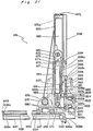
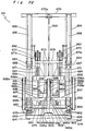
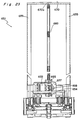
- Figs. 21, 22, 23 are the side, back, and frontal views of this column device 651.
- the column device 651 is such that it can slide along the top of the subframe members 647 on its slide pads 652, which sandwich the top rails of the subframe members 647.
- the column device 651 also comprises a pair of columns 655 made of H-channel steel resting on the channel steel 653; the tops of the columns 655 are connected by horizontal plate 670, and the bottoms are connected by a bottom plate 680 shown in Fig. 21.
- a hydraulic motor 659 is mounted on the bottom plate 680 in front of the columns 655; a sprocket 657 is mounted on the rotor of the hydraulic motor 659, and sprockets 654, 656 are provided before and after the sprocket 657 just below the bottom plate 680, i.e., at a level near the top of the subframe members 647. These three sprockets 654, 656, and 657 are connected by a single chain 658.
- the chain 658 has one end 658a fixed to the center portion 649a of the plate 649 connecting the front ends of the subframe members 647, and is passed lengthwise between the subframe members 647 up around the sprocket 654, and then down and back around sprockets 657, 656, respectively, over the shaft 648 connecting the back ends of the subframe members 647, and the other end 658b is secured at the center portion 646a at the back of the chassis frame 646.
- the channel width between the subframe members 647 is the minimum required to allow passage of the chain 658, thereby making it possible to reduce the overall height of the carrier 645.
- a carrier-side top connecting member 661 and a carrier-side bottom connecting member 691 are also provided at the back of the columns 655 in such a way that they can move freely up and down, respectively, as indicated by arrow Z in the figure.
- the carrier-side top connecting member 661 comprises a pair of plates 662 with an L-shaped cross section connected at the top and bottom, respectively by horizontal rods 666, 688, a holding member 663 mounted on the vertical rod 667 connecting the centers of the horizontal rods 666, 688, a coupling pin 665 which passes through and connects both sides of the holding member 663, a pair of right and left arms 668, and operating pins 69.
- the holding member 663 is provided with a U-shaped portion facing the back.
- One end of the arms 668 is mounted with one end rotating freely on the studs 668a provided on vertical rod 667, and the other end and the approximate center of the arms 668 rotating freely and with play in the long direction on the coupling pin 665 and operating pin 669.
- a pair of hydraulic cylinders 671 is mounted inside the pair of columns 655 with the bottom ends of the tubes connected to the bottom plate 680 by pin 674, and the top ends of the piston rods 671a of the hydraulic cylinders 671 connected by shaft 675, to the ends of which are mounted sprockets 682.
- a pair of support members 673 is provided vertically at approximately the center of the shaft 675, and a sprocket 686 is mounted between the bottom ends of the support members 673.
- a pair of chains 684 attached at the near bottom 681 of the tubes of the hydraulic cylinders 671 are mounted around the sprockets 682 and drop vertically, and are connected to the ends 688a of the horizontal rod 688 of the carrier-side top connecting member 661.
- a chain 685 fixed at center member 670a of the top plate 670 is wound around the sprocket 686 and carried up and is connected at the center part 688b of the horizontal rod 688.
- the carrier-side top connecting member 661 can be lifted up by the chains 684, while the carrier-side top connecting member 661 is permitted to rise with the chain 685 wrapped around and constrained by the sprocket 686.
- the carrier-side top connecting member 661 can descend of its own weight. It is to be noted that the carrier-side top connecting member 661 is mounted such that it can travel up and down along the channels inside and between the right and left columns 655 on the rollers 664 mounted on the sides of the plates 662.
- the carrier-side bottom connecting member 691 comprises a pair of side plates 697 covering the sides of the columns 655, a pair of top and bottom rods 692, 693 horizontally connecting the side plates 697, and a holding member 695 mounted at the center of the rods 692, 693.
- a pair of rotating members 803, a twist spring 804, and a pair of locking members 805 mounted to the holding member 695.
- the holding member 695 is provided with a U-shaped portion horizontal and projecting out toward the back.
- the locking members 805 are mounted on stud 695b at the top end of the holding member 695 so that they are able to rotate freely around the stud 695b; when the locking members 805 are hanging perpendicularly of their own weight, at least part of the U-shaped portion of the holding member 395 is closed.
- the rotating members 803 are simple L-shaped members with that member corresponding to the short leg of the L mounted on a stud 695a provided at a point near the connecting rod 692 at the top side of the holding member 695.
- the rotating members 803 are provided with a connecting plate 809 connecting the long legs of both rotating members 803 so that the rotating members 803 turn around the stud 695a together, and are also driven continuously around to the right by the force of the twist spring 804 as shown in Fig. 21.
- the holding member 663 pushes the connecting plate 809 downward and stops at connecting rod 692, and the rotating members 803 are not in contact with any part of the freely rotating locking members 805. Therefore, the locking members 805 are free to rotate around the stud 695b, and the U-shaped portion of the holding member 695 becomes open, i.e., the couple is released.
- the rotating members 803 are turned around to the right by the action of the twist spring 804, contact the side of the connecting rod 692, and is stopped.
- the carrier-side bottom connecting member 691 is connected to the bottom end of the piston rods 696a (pointing down) of the hydraulic cylinders 696 mounted to the back of the columns 655 by the bracket 694.
- Sliding members 699 are provided inside the side plates 697 so that when the piston rods 696a of the hydraulic cylinders 696 are retracted, the carrier-side bottom connecting member 691 can move up and down along the columns 655.
- the hydraulic motor 659 on the column device 651, the hydraulic cylinders 671, and the hydraulic cylinders 696 are driven by a hydraulic circuit as shown in Fig. 24.
- This hydraulic circuit comprises a hydraulic pump 748, tank 840, filter 841, a six port, three position directional control valve 842 for driving the hydraulic cylinder, a similar six port, three position directional control valve 843 for driving the hydraulic motor, non-return valves 845, 846, and flow control valves 847, 848 connected to the ports of the hydraulic motor 659.
- the hydraulic pump 748 and tank 840 are mounted at the side of the chassis frame 646.
- the directional control valves 842, 843 are mounted inside the column device 651.
- the hydraulic cylinders 671, 696 are connected in parallel in the column device 651, and are connected to the ports of the directional control valve 842 by a pair of lines 851, 852; the flow control valves 847, 848 connected to the ports of the hydraulic motor 659 are connected to the ports of the directional control valve 843 by another pair of lines 853, 854.
- the directional control valves 842, 843 in the column device 651 are connected to the hydraulic pump 748 and tank 840 on the side of the chassis frame 646 by a pair of return lines 849, 950 to form one complete circuit.
- the directional control valves 842, 843 are able to move a spool by means of solenoids 842a, 842b and 843a, 843b, respectively, to change the operating position; when current is applied to the solenoids 842a, 843a, an intersecting fluid path is formed, and when current is applied to the solenoids 842b, 843b, a direct fluid path is formed.
- the solenoids 842a, 842b and 843a, 843b are controlled by an electrical circuit as shown in Fig. 25.
- This circuit comprises a 24-V battery 300, a limit switch 870 and a limit switch 871, each with a normally open contact NO and a normally closed contact NC, and an operating switch 860 with four normally open contacts U, D, F, B.
- the limit switches 870, 871 are mounted at the front and rear, respectively, of the subframe members 647.
- the limit switch 870 contacts the front of the column device 651, and the normally open contact NO closes and the normally closed contact NC opens.
- the limit switch 871 contacts the back of the column device 651, and the normally open contact NO closes and the normally closed contact NC opens.
- the operating switch 860 is provided near the driver seat, and the operator can close any of the contacts U, D, F, B as desired.
- the battery 900 is connected to the contacts NO, NC of both limit switches 870, 871; the normally open contacts NO of the limit switches 870, 871 are connected by a common wire to the contacts U, D of the operating switch 860.
- the normally closed contact NC of the limit switch 870 is individually connected to contact F of the operating switch 860, and the normally closed contact NC of the limit switch 871 is connected discretely to contact B of the operating switch 860.
- the contacts U, D, F, B of the operating switch 860 are respectively connected to the solenoids 842a, 842b, 843a, 843b.
- the limit switches 870 and 871 and the operating switch 860 are connected serially to each of the solenoids 842a, 842b, 843a, 843b.
- each solenoid also has a serially connected diode 844 for circuit protection.
- the normally open contact NO of the limit switch 870 is closed and the normally closed contact NC is open, and the normally open contact NO of the limit switch 871 is open and the normally closed contact NC is closed (the normal position).
- the directional control valve 842 can be switched from a neutral position to the operating position at which an intersecting circuit or a direct circuit is formed, or the directional control valve 843 can be switched from a neutral position to the operating position at which a direct circuit is formed.
- the limit switch 870 When the column device 651 is at the back of the subframe members 647, the limit switch 870 is in the normal position, but the limit switch 871 is set with the normally open contact NO closed and the normally closed contact NC open.
- the directional control valve 842 can be switched from a neutral position to the operating position at which an intersecting circuit or a direct circuit is formed, or the directional control valve 843 can be switched from a neutral position to the operating position at which an intersecting circuit is formed.
- both limit switches 870, 871 are in the normal position.
- the directional control valve 843 can be switched from a neutral position to either operating position, but the directional control valve 842 cannot be switched from the neutral position to either operating position.
- both directional control valves 842, 843 are at the neutral position as shown in Fig. 24, the fluid sent from the tank 840 through the filter 841 by the hydraulic pump 748 to the line 849 passes through the directional control valves 842, 843, and is vented directly into the tank 840 through the line 850 connecting the directional control valve 843 and the tank 840.
- the hydraulic motor 659 can be driven by the directional control valve 843
- the hydraulic cylinders 671 and the hydraulic cylinders 696 can be driven by one directional control valve 842
- the two directional control valves 842, 843 can be controlled by a single operating switch 860.
- the container 601 comprises a box-shaped container body 602, pillar-shaped support members 303, a top connecting member 611 on the container, a bottom connecting member 616 on the container, and chains 621, 640.
- the container body 602 is composed of symmetrical pillar-shaped rear columns 605, front columns 613, side columns 630 (shown only on one side), rear beam 604, front beam 614, top side frames 610, bottom side frames 69, front panel 612, bottom panel 619, legs 620, and top and side panels not shown in the figure.
- a channel 612a with a U-shaped cross section running vertically is provided at the center of the front panel 612 and the front beam 614.
- the support members 603 fit inside the rear columns 605 so that they can be raised and lowered freely, and are each provided with a rectangular ground member 607 on the bottom.
- the bottoms of these support members 603 are connected by a single shaft 608, which causes both support members 360 to ascend and descend in unison.
- the top connecting member 611 of the container is a semicircular shaped member the ends of which are attached horizontally at the upper center of the front panel 612.
- the container-side bottom connecting member 616 comprises a engaging member 617 and a sliding member 618.
- the engaging member 617 has a U-shaped portion 617c mounted to a vertical rectangular plate 617b perpendicular to the U-shaped portion 617c with reinforcing ribs 617d bridging therebetween, and a vertical rectangular plate 617a perpendicular to the rectangular plate 617b.
- Said container-side bottom connecting member 616 is constructed in such a way that the rectangular plate 617a of the engaging member 617 and the channel in the sliding member 618 intersect.
- a pair of guides 615 formed from channel steel are provided inside the channel 612a of the front beam 614 and front panel 612 with the channels facing inside and parallel to one another with a gap therebetween; the rectangular plate 617a of the engaging member 617 is fit into this gap, and the outside surface of the guides 615 slides in contact with the inside surface of the channel in sliding member 618.
- a pair of chains 621 is provided symmetrically (shown only on one side in the figure) with one end connected to the side of the sliding member 618, the chain passing through the front beam 614 and mounted on a pair of sprockets 623, 624 to guide the chain first horizontally from the up vertical and then down vertically from the horizontal, through the front column 613, around the sprocket 625 at the bottom of the front column 613 so that the chain is carried from the vertical horizontally to the back through the bottom side frame 609, around the sprocket 626 at the back end of the bottom side frame 609 from the front-back horizontal to the vertical, and the other end is connected to the top 603a of the support member 603.
- the other chain 640 likewise has one end connected to the bottom of the engaging member 617, is passed vertically at the front of the container body 602, guided from the vertical to the horizontal lengthwise by the sprocket 642 provided at the front bottom of the container body 602, underneath the bottom panel 619, around the sprocket 643 provided at the back bottom of the container body 602, and the other end is connected to the shaft 608.
- the support members 603 are extended down via the chain 621, and the other chain 640 is loosened, allowing the shaft 608 to descend, i.e., allowing the support members 603 to descend.
- the support members 603 are lifted by the chain 640 via the shaft 608, and the other chain 621 is loosened to allow the support members to rise.
- the container 601 and carrier 645 as described above operate as follows.
- the carrier 645 and the container 601 are positioned as shown in Fig. 26 (a) at the start of the loading operation with the column device 651 at the back of the subframe members 647, and the bottom connecting member 616 in the up position with the support members 603 retracted inside the rear columns 605. Also, the piston rods 671a of the hydraulic cylinders 671 are retracted, and the piston rods 696a of the hydraulic cylinders 696 are extended. The carrier-side top connecting member 661 and the carrier-side bottom connecting member 691 are in contact at lowest position in the column device 651, and the holding members 663, 695 are therefore released.
- the directional control valve 842 switches to the intersecting channel operating position.
- Current is thus supplied to the solenoid 842a because the normally open contact NO of the limit switch 871 at the back of the subframe members 647 is on at this time.
- the piston rods 671a of the hydraulic cylinders 671 are extended, and the carrier-side top connecting member 661 is raised by the chains 684 complete with the sprockets 682. Note that the bottom of the sprocket 686 is constrained by the chain 685.
- the carrier-side bottom connecting member 691 remains stopped at the bottom of the columns 655 because this operation of the operating switch 860 causes the piston rods 696a of the hydraulic cylinders 696 to extend simultaneously.
- the holding member 663 is automatically closed by the coupling pin 665, and the holding member 695 is automatically closed by the locking members 805, i.e., the carrier-side top connecting member 661 and the container-side top connecting member 611, and the carrier-side bottom connecting member 691 and the container-side bottom connecting member 616 are automatically coupled.
- the front of the container 601 is lifted via the container-side top connecting member 611 by the carrier-side top connecting member 661, and at the same time the back of the container 601 is lifted by the support members 603 as described below.
- the container-side bottom connecting member 616 is held stationary with respect to the ground by the carrier-side bottom connecting member 691 which is at rest, when the container body 602 rises, as shown in Fig. 26 (b), the container-side bottom connecting member 616 descends relative to the container body 602.
- This action drives the chain 621 and the chain 640, causing the support members 603 to extend down, thus lifting the back of the container 601.
- the front of the container 601 is lifted by the container-side top connecting member 611, and the back is lifted by the support members 603, this action is synchronized, and the container 601 thus remains level as it is raised.
- the operating switch 860 When the main beam 632 at the bottom of the container body 602 reaches the same height as the carrier 645 subframe 647, the operating switch 860 returns to the normal state, the directional control valve 842 returns to the neutral position, the operation of the hydraulic cylinders 671 stops, and lifting of the container stops. Next, the carrier 645 brake is released and the transmission is put into neutral; an operation is then performed whereby the contact F of the operating switch 860 is closed, thus supplying current to the solenoid 843a and switching the directional control valve 843 to the operating position forming an intersecting circuit. The hydraulic motor 659 on the column device 651 is then driven to move the column device 651 forward relative to the subframe members 647.
- the directional control valve 842 does not change its operating position because both the limit switches 870, 871 at the front and back of the subframe members 647 are in the normal state. Therefore, the hydraulic cylinders 671, 696 are not driven, and the front and back of the container 601 remain at the same height.
- the piston rods 671a of the hydraulic cylinders 671 are also retracted at this time, but because the carrier-side top connecting member 661 is connected to the container-side top connecting member 611, the piston rods 671a are held at the height of the container-side top connecting member 611.
- the sprockets 682 are constrained vertically by the chains 685 and chains 684, and are also held at the same height.
- the container-side bottom connecting member 616 connected to the carrier-side bottom connecting member 691 is raised, and the support members 603 are raised from the ground by the chains 621, 640. It is to be noted that the container 601 can be unloaded from the carrier 645 by simply reversing this procedure.
- a container carrier can load and unload a container 601 to the carrier 645 while holding the container 601 in a level position. Moreover, the carrier-side top connecting member 661 and container-side top connecting member 611, and the carrier-side bottom connecting member 691 and the container-side bottom connecting member 616 are automatically coupled and released with the loading and unloading action. In addition, because the carrier 645 is pulled back by chain 658 during the loading operation by driving the hydraulic motor 659 on the column device 651 with the transmission in neutral, it is easy to control the speed of movement and to slow the horizontal movement. By slowing the horizontal movement, it is possible to prevent the carrier 645 and the container 601 from colliding hard and being damaged.
- the column device 651 can be moved forward and back along a single chain 658 positioned between the subframe members 647 on the chassis frame 646, the channel width between the subframe members 647 is the minimum required to allow passage of the chain 658, and by thereby making this channel as shallow as possible, the overall height of the carrier 645 can be reduced.
- limit switches 870, 871 which are on when the column device 651 is positioned at the front or the back of the subframe members 647 are provided at the front and the back of the subframe members 647, and the operating switch 860 controlling the switching of the directional control valve 842 is connected in series with the limit switches 870 and 871, a change in the height of the front or the back of the container 601 can be prevented even if the operator mistakenly operates the operating switch 860 during horizontal movement of the container 601 relative to the carrier 645. Therefore, it is possible to prevent the container 601 from tilting, and it is thus possible to prevent the contents of the container 601 from falling over.
- the container and container carrier according to the present invention make it possible to load and unload a container safely and unfailingly while retaining a level attitude, and can therefore be used for the transportation of pianos, furniture, breakables, containers holding fluids or liquids, and other similar goods.
Landscapes
- Engineering & Computer Science (AREA)
- Mechanical Engineering (AREA)
- Transportation (AREA)
- Handcart (AREA)
- Forklifts And Lifting Vehicles (AREA)
- Warehouses Or Storage Devices (AREA)
Abstract
Description
- The present invention relates to a container carrier and a container which can be loaded and unloaded from the carrier according to the preamble part of
claim 1 and 3. - Such a container and container carrier are known from DE-B-2 041 574.
- There is the following (Japanese patent S52-57615), as a conventional container carrier. This container carrier comprises a articulated loading arm provided on the carrier body, and a container provided on the top front an engaging member which catches on a hook on the end of the loading arm. When the container is loaded onto the carrier, the hook on the end of the loading arm engages the engaging member on the front of the container, and lifts the container up onto the body at an angle. When the container is unloaded, it is similarly lowered at an angle from the carrier to the ground by the loading arm.
- However, because the container is diagonal to the horizontal when it is loaded and unloaded from a conventional container carrier as thus described, it cannot be loaded with such articles as pianos, furniture, fragile objects and breakables, tanks containing liquids, and similar goods. Such containers are therefore in practice limited to use with rubbish and other waste materials.
- Therefore, the first object of the present invention is to provide a container carrier and a container which can be loaded and unloaded from the carrier while retaining a level attitude, and can therefore be used for the transportation of pianos, furniture, breakables, tanks containing liquids, and similar goods.
- In addition, a second object of the present invention is to provide a container carrier and a container which can be loaded and unloaded from the carrier while retaining a horizontal attitude, and in addition can prevent the container from bouncing up from the carrier when bumps and holes in the road are hit during transportation, and is thus able to prevent damage to the container and the carrier, and so enables the driver to relax while driving.
- A third object of the present invention is to provide a container carrier from which a container can be loaded and unloaded while retaining a level attitude, and which enables the container to automatically engage and disengage with the carrier.
- A fourth object of the present invention is to provide a container carrier from which a container can be loaded and unloaded while retaining a level attitude, and which can prevent operational errors, can prevent the container from sloping even if the operator does err in operation, and therefore prevents the cargo inside the container from falling over.
- These objects are achieved by a container according to claim 1 and a container carrier according to
claim 3 - It is preferable to provide, for example, a roller at the bottom end of the support member, or a ground member which contacts the ground and is unmovable.
- When the container is loaded on the carrier, it is possible to synchronize the front and back of the container body so that the container remains level by raising the front of the container by lifting the top connecting member at the front of the container body by means of the member of the carrier, and holding the bottom connecting member at the front of the container fixed with respect to the ground, transferring the motion of the bottom connecting member relative to the container body to the support member at the back of the container by means of the transmitting means, and extending the support member at the back of the container down to raise the back of the container. When the container is raised to approximately the same height as the bed of the carrier, the container can be advanced forward onto the carrier by pulling forward, for example, on the couple while supporting the back of the container with the support member on the ground. After this, the support member can be lifted from the ground by operating a bottom connecting member, for example, by a means on the carrier side. When this container is lowered to the ground, a level posture can still be maintained by simply reversing the procedure just described.
- Furthermore, instead of operating a bottom connecting member to lift the support member from the ground, the support member may also be folded and secured so that it is not supporting the container against the ground.
- In addition, by passing the transmitting means through a side frame on the container, the frame size can be enlarged to the maximum limit possible when there are restrictions on the outside dimensions of the container body. As a result, the container capacity can be increased to the maximum limit.
- When the container is loaded on the carrier, it is possible to synchronize the front and back of the container body so that the container remains level by raising the front of the container via the top connecting member by means of the top connecting member on the carrier, and holding the bottom connecting member at the front of the container fixed with respect to the ground by means of the carrier-side bottom connecting member, transferring the motion of the container-side bottom connecting member relative to the container body to the support member at the back of the container by means of the transmitting means, and extending the support member at the back of the container down to raise the back of the container. When the container is raised to approximately the same height as the bed of the truck, the container can be advanced forward onto the carrier by pulling forward, for example, on the couple while supporting the back of the container with the support member on the ground. After this, the support member can be lifted from the ground by operating, for example, the bottom connecting member on the container and carrier by a bottom connecting member drive means on the carrier side. When this container is lowered to the ground, a level posture can still be maintained by simply reversing the procedure just described.
- It is to be noted that when the container is lifted to the same height as the vehicle, the container can also be loaded onto the vehicle by backing the vehicle up instead of pulling forward on the couple.
- In order to achieve the second object, a container carrier according to the present invention is characterized in that an engaging member having a pin is provided at the center or rear part of one of the container or the carrier, and in the other of the container or the carrier is provided a guide member; this guide member comprises a tapered guide portion, which is provided to guide the pin of the engaging member and raise the carrier body so that the bottom of the container connects with the top of the carrier body when the container is loaded horizontally with an even gap to the carrier, and a horizontal contact portion, which is formed in contact with the guide portion and which contacts the pin of the engaging member when the container is loaded completely onto the carrier.
- When the container is loaded onto the carrier, by lifting the body so that the guide portion of the guide portion guides the pin of the engaging member and the bottom of the container connects with the top of the body, when the container is completely loaded on the carrier, the pin in the engaging member will be in contact with the contact portion of the guide portion. Specifically, the center or rear parts of the container and carrier are coupled together by the guide members and engaging member. On the other hand, the front of the container is coupled firmly to the carrier by the top connecting members on the carrier and container and by the bottom connecting members on the carrier and container. The container is therefore coupled at both front and back to the carrier. As a result, when bumps and holes are hit in the road while driving, the container will not bounce up from the carrier, and damage to the container and carrier does not occur. The driver can therefore relax while driving.
- In order to achieve the third object, the container carrier according to the present invention is characterized in that the carrier-side bottom connecting member comprises a holding member with a U-shaped portion which can accept the engaging member of the container-side bottom connecting member , and a closing member which can close an opening of the U-shaped portion when the engaging member is enclosed in the holding member, and an operating mechanism which cause the closing member to open or close the opening of the U-shaped portion in connection with the approach or separation of the carrier-side top connecting member to the carrier-side bottom connecting member.
- When the carrier-side bottom connecting member is in the down position in the column device, and the carrier-side top connecting member descends and contacts the carrier-side bottom connecting member, the operating mechanism causes the closing member to open the opening of the U-shaped portion of the holding member in connection with the action of the two connecting members meeting. Thus, the engaging member of the container-side bottom connecting member easily couples with and separates from the U-shaped portion of the holding member of the carrier-side bottom connecting member. Also, when the carrier-side bottom connecting member is in the down position in the column device, and the carrier-side top connecting member rises and separates from the carrier bottom connecting member, the operating mechanism causes the closing member to close the opening of the U-shaped portion of the holding member in connection with the action of the two connecting members separating. Therefore, when both connecting members are in contact, the engaging member of the container-side bottom connecting member fitted to the holding member cannot separate from the holding member. Specifically, by driving the carrier-side bottom connecting member vertically, the carrier-side top and bottom connecting members are automatically connected or released. Therefore, there is no danger of the container dropping and being damaged when being raised or lowered.
- Furthermore, it is preferable that the closing member is a connecting pin, and the above operating mechanism releases the connection of the holding member and the engaging member with the connecting pin in conjunction with the descending action of the carrier-side top connecting member as it approaches the carrier-side bottom connecting member when the carrier-side bottom connecting member is at the lowest position in the column device, and connects the holding member and the engaging member with the connecting pin in conjunction with the ascending action of the carrier-side top connecting member as it separates from the carrier-side bottom connecting member when the carrier-side bottom connecting member is at the lowest position in the column device.
- Also, it is possible that the above operating mechanism comprises a spring member, a roller, and a bell crank on the carrier-side bottom connecting member with first, second, and third arms, wherein the first arm of the bell crank is mounted on the connecting pin, the spring member constantly applies pressure to the second arm of the bell crank, and applies an operating force to the first arm in the direction causing the connecting pin to connect the holding member and the engaging member, and the roller, mounted on the third arm of the bell crank, moves the first arm of the bell crank in the direction which causes the coupling of the holding member and the engaging member to be released by contacting a pressure plate provided at the carrier-side top connecting member when the carrier-side top connecting member approaches the carrier-side bottom connecting member; and when the carrier-side top connecting member separates from the carrier-side bottom connecting member, it separates from the pressure plate and permits the connecting pin to connect the holding member and the engaging member.
- It is possible that the above operating mechanism comprises an arm provided on the carrier-side bottom connecting member, a spring member, and an operating pin; one end of the arm is mounted on the carrier-side bottom connecting member so that it can rotate freely, and the other end is connected to the connecting pin; the spring member applies constant pressure to the other end of the arm in the direction causing the connecting pin to couple the holding member and the engaging member; and the operating pin is mounted vertically with the bottom end at the approximate center of the arm; when the carrier-side top connecting member descends and approaches the carrier-side bottom connecting member, the bottom of the carrier-side top connecting member contacts the operating pin, and the aforementioned other end of the arm is moved in the direction causing the coupling of the holding member and the engaging member to be released; when the carrier-side top connecting member separates from the carrier-side bottom connecting member, the operating pin separates from the bottom of the carrier-side top connecting member and is permitted to couple the holding member and the engaging member.
- It is preferable that the carrier-side bottom connecting member comprises a holding member with a U-shaped portion which accepts the engaging member of the container-side bottom connecting member; a lock member provided at the opening of the U-shaped portion and pivoting on the holding member so as to rotate freely to enable coupling and decoupling of the engaging member with the U-shaped portion of the holding member; and a rotating member which pivots on the holding member, rotates up and down in conjunction with the contact and separation of the carrier-side top connecting member, and when the rotating member is in an engaging position with the lock member, holds the coupling of the engaging member in the U-shaped portion of the holding member with the lock member.
- When the carrier-side bottom connecting member is in the down position in the column device, and the carrier-side top connecting member descends and contacts the carrier-side bottom connecting member, the bottom of the carrier-side top connecting member presses against the rotating member, causing it to rotate down and causing the lock member to open the U-shaped portion. Thus, the engaging member of the container-side bottom connecting member easily couples with or separates from the U-shaped portion of the holding member of the carrier-side bottom connecting member. On the other hand, when the carrier-side bottom connecting member is in the down position in the column device, and the carrier-side top connecting member rises and separates from the bottom connecting member, the bottom of the top connecting member separates from the rotating member, stopping the rotating member in the engaging position and thereby holding the engaging member in the U-shaped portion. Therefore, when both the top and bottom carrier-side connecting members are in contact, the engaging member of the container-side bottom connecting member coupled with the holding member of the carrier-side bottom connecting member cannot separate from the holding member. Specifically, by driving the carrier-side top connecting member vertically, the carrier-side top connecting member and the container-side bottom connecting member are automatically connected or released. Therefore, there is no danger of the container dropping and being damaged when being raised or lowered.
- Furthermore, if the carrier comprises a column drive mechanism which moves the column device forward and back, when the container is moved levelly on the container carrier during loading or unloading, the speed can be controlled and the container can be moved levelly by driving the column drive mechanism. It is to be noted that when a roller is provided on the bottom of the support member of the container, the container is moved levelly on the container carrier with the carrier brakes applied and the carrier stopped. However, when the bottom of the container support member is provided with a ground member, the transmission of the carrier is set in neutral, the column drive mechanism is operated to move the carrier levelly to the ground so that the container is thus moved horizontally relative to the body.
- Furthermore, when the carrier comprises a carrier-side bottom connecting member drive means which moves the carrier-side bottom connecting member vertically, the container support member can be raised from the ground by operating the carrier-side bottom connecting member drive means after the container is loaded on the carrier.
- In order to achieve the fourth object, the container carrier according to the present invention comprises a column device provided to move forward and back on a subframe mounted on a chassis frame, a carrier-side top connecting member provided on the column device so that it moves vertically and can couple with a container-side top connecting member, a carrier-side bottom connecting member provided on the column device so that it moves vertically and can couple with the container-side bottom connecting member, a lift chain, one end of which is fixed to the carrier-side top connecting member and the other end of which is connected to the column device, a lift sprocket to an upper side of which is wound the lift chain, a first fluid cylinder which raises and lowers the lift sprocket by the extension and contraction of a piston rod, and a second fluid cylinder which raises and lowers the carrier-side bottom connecting member by the extension and contraction of a piston rod, lines which connect the first fluid cylinder and the second fluid cylinder in parallel, a single control valve which switches the flow of fluid in the direction causing the first fluid cylinder and the second fluid cylinder to extend or retract simultaneously, and a subchain, one end of which is fixed to the top of the column device and the other end of which is fixed to the carrier-side top connecting member, which is wound from below onto a subsprocket provided on a moving part of the first fluid cylinder; whereby when the first fluid cylinder and the second fluid cylinder are driven together in one of extension and retraction directions and the container is loaded on the subframe, the carrier-side top connecting member coupled with the container-side top connecting member is raised, while when the carrier-side bottom connecting member is lowered and the control valve is switched in the direction which causes the first and second fluid cylinders to move in the other of the extension and retraction directions, the action of the first fluid cylinder is constrained by the subchain through the subsprocket, and the carrier-side top connecting member is stopped at the raised position.
- The container is loaded as follows. Here, the retraction and extension of the first and second fluid cylinders respectively cause the carrier-side top connecting member to descend and the carrier-side bottom connecting member to descend. The column device is located at the back of the vehicle, and when the container-side top connecting member and the carrier-side top connecting member, and the container-side bottom connecting member and the carrier-side bottom connecting member are each connected to the other, the control valve is first operated to switch the fluid flow so that the first and second fluid cylinders simultaneously extend. This causes the front of the container to be lifted by the carrier-side top connecting member via the lift chain and the lift sprocket, while the back of the container is lifted by the extension of the support member so that the container is lifted while retaining a level attitude. At this time, an operation is performed whereby the column device moves forward relative to the subframe, and the container is thus moved levelly over the subframe. After this horizontal movement is completed, the control valve is operated to change the fluid flow in the direction causing the first and second fluid cylinders to simultaneously retract. Thus, the first fluid cylinder is constrained by the subchain via the subsprocket and held in the extended position, and the lift chain cannot disengage from the lift sprocket. On the other hand, the second fluid cylinder is not constrained and retracts, and the support member at the back of the container is stored inside the rear column.
- Next, when the container is unloaded from the vehicle, an operation is executed whereby the column device is moved to the back relative to the subframe, and the support member is lowered; after that when the container is lowered, the control valve is operated for both fluid cylinders, and because the weight of the container is bearing on the first fluid cylinder, the first fluid cylinder contracts before the second fluid cylinder, and the container is lowered. Because there is only one control valve for both cylinders, it is not possible to mistakenly operate the other fluid cylinder. Therefore, tilting of the container is prevented, and the contents of the container will not fall over.
- To further achieve the fourth object, the container carrier according to the present invention comprises a column device provided to move a subframe mounted on a chassis frame forward and back, a carrier-side top connecting member provided on the column device so that the carrier-side top connecting member moves vertically and can couple with a container-side top connecting member, a carrier-side bottom connecting member provided on the column device so that the carrier-side bottom connecting member moves vertically and can couple with a container-side bottom connecting member, drive means which raise and lower the carrier-side top connecting member and the carrier-side bottom connecting member; a limit switch which operates when the column device is positioned on the subframe at the back; and an operating switch which enables the operation of the drive means only when the limit switch operates.
- When the column device is positioned at the back of the subframe, the limit switch operates. Therefore, by operating the operating switch connected to this limit switch, the drive means can be operated. Specifically, when the column device is positioned at the back of the subframe, the carrier-side top connecting member moves up or down, the carrier-side bottom connecting member remains stationary relative to the ground, and the container remains level when ascending and descending.
- However, when the column device is positioned in the middle of the subframe, the limit switch does not operate. The drive means will therefore not operate even if a worker mistakenly operates the operating switch while the container is moving horizontally. The carrier-side top connecting member and the carrier-side bottom connecting member will therefore not move vertically, and the front and back of the container will be maintained at the same height. Tilting of the container is thus prevented, and the contents of the container will also not fall over.
-
- Fig. 1 and Fig. 2 are oblique views of the container and carrier, respectively, according to a first embodiment of a container carrier according to the present invention; Figs. 3 (a) and (b) are side and rear views, respectively, of the column device on the carrier; Figs. 4 (a), (b), and (c) are figures describing the operation of the column device; Figs. 5 (a) to (d) are figures describing the operation of the container carrier; Fig. 6 shows the container carrier when container loading is completed;
- Fig. 7 and Fig. 8 are oblique views of the container and carrier, respectively, according to a second embodiment of a container carrier according to the present invention; Figs. 9 (a) and (b) are side and rear views, respectively, of the column device on the carrier; Figs. 10 (a), (b), and (c) are figures describing the operation of the column device; Fig. 11 shows the container carrier when container loading is completed;
- Fig. 12 and Fig. 13 are side views of a container carrier according to a third embodiment according to the present invention; Fig. 14 and Fig. 15 are top and rear views, respectively, of the carrier-side bottom connecting member on the container carrier; Fig. 16 is a cross section at IV-IV in Fig. 15; Figs. 17 (a), (b), and (c) are figures describing the operation of the column device on the container carrier;
- Fig. 18 shows how Fig. 18 (a) and Fig. 18 (b) fit together; Figs. 18 (a) and (b) are side views of the front and rear of the container carrier according to a fourth embodiment of the present invention; Fig. 19 is an oblique view of the carrier from the rear of this container carrier; Fig. 20 is an oblique view of the container from the front of this container carrier; Fig. 21, Fig. 22, and Fig. 23 are views from the side, rear, and front, respectively, of the column device of this carrier; Fig. 24 shows the hydraulic circuit of this carrier; Fig. 25 shows the electrical circuit of this carrier; and Figs. 26 (a) to (d) describe the operation of loading the container to the carrier.
- A container and container carrier according to the present invention will be described hereinbelow with reference to the accompanying figures, wherein Fig. 1 and Fig. 2 show the container 1 and
carrier 45 according to a first embodiment of the present invention. - As shown in Fig. 1, the container 1 comprises a box-shaped
container body 2, pillar-shapedsupport members 3, a top connectingmember 11 on the container, abottom connecting member 16 on the container, andchains container body 2 is composed of symmetrical pillar-shapedrear columns 5,front columns 13, side columns 30 (shown only on one side), rear beam 4,front beam 14, top side frames 10, bottom side frames 9,front panel 12,bottom panel 19,legs 20, and top and side panels not shown in the figure. Achannel 12a with a U-shaped cross section running vertically is provided at the center of thefront panel 12 and thefront beam 14. Thesupport members 3 fit inside therear columns 5 so that they can be raised and lowered freely, and are each provided with aroller 7 mounted on the bottom end by way of abracket 6. The bottoms of thesesupport members 3 are connected by asingle shaft 8, which causes bothsupport members 3 to ascend and descend in unison. Thetop connecting member 11 of the container is a semicircular member the ends of which are attached on a horizontal line at the upper center of thefront panel 12. - The container-side
bottom connecting member 16 comprises a key-shaped engagingmember 17, which has arectangular plate 17a and aring 17b, and a channel-shaped slidingmember 18; thebottom connecting member 16 is constructed in such a way that therectangular plate 17a and the bottom of the channel in the slidingmember 18 intersect. A pair ofguides 15 formed from channel steel are provided inside thechannel 12a of thefront beam 14 andfront panel 12 with the channels facing inside and parallel to one another with a gap in between; therectangular plate 17a of the engagingmember 17 is fit into this gap, and the outside surface of theguides 15 slides in contact with the inside surface of the channel in slidingmember 18. The completebottom connecting member 16 can thereby slide up and down. - A pair of
chains 21 is provided symmetrically (shown only on one side in the figure) with one end connected to the side of the slidingmember 18, the chain passing through thefront beam 14 and mounted on a pair ofsprockets front column 13, around thesprocket 25 at the bottom of thefront column 13 so that the chain is carried from the vertical horizontally to the back through thebottom side frame 9, around thesprocket 26 at the back end of thebottom side frame 9 from the lengthwise horizontal to the vertical, and the other end is connected to the top 3a of thesupport member 3. Theother chain 40 likewise has one end connected to the bottom of the engagingmember 17, is passed vertically at the front of thecontainer body 2, guided from the vertical to the horizontal lengthwise by thesprocket 42 provided at the front bottom of thecontainer body 2, under thebottom panel 19, guided vertically by thesprocket 43 provided at the back bottom of thecontainer body 2, and the other end is connected to theshaft 8. - Therefore, by pushing the container-side
bottom connecting member 16 down from the position shown in the figure, thesupport members 3 are extended down via thechain 21, and theother chain 40 is loosened, allowing theshaft 8 to descend, i.e., allowing thesupport members 3 to descend. Conversely, when thebottom connecting member 16 of the container is moved up from the down position, thesupport members 3 are lifted by thechain 40 via theshaft 8, and theother chain 21 is loosened to allow the support members to rise. - Fig. 2 shows the
carrier 45. Thiscarrier 45 is provided with channelledsubframes 47 parallel and with the channels facing the inside on thechassis frame 46. Thecolumn device 51 is provided on thesubframes 47 so that it can move freely back and forth in the direction indicated by arrow X. Thiscolumn device 51 is such that it can slide along the top of thesubframes 47 on itsslide pads 52, which sandwich the top rails of thesubframes 47. Thecolumn device 51 also comprises a pair ofcolumns 55 made of H-channel steel; the tops of thecolumns 55 are connected byhorizontal plate 70, and the bottoms are connected by a bottom plate not shown in the figure. This bottom plate is connected to the pair ofchains 58 which turn around the two pairs ofsprockets sprocket 60 is provided on the shaft connecting therear sprockets 57, and is driven by ahydraulic motor 59. Therefore, thishydraulic motor 59 moves thecolumn device 51 forward and back in the direction of arrow X by driving thechains 58. - In addition, a carrier-side
top connecting member 61 and a carrier-sidebottom connecting member 91 are also provided at the back of thecolumns 55 in such a way that they can move freely up and down, respectively, as indicated by arrow Z. As shown in Figs. 3 (a) and (b), the carrier-sidetop connecting member 61 comprises a pair ofplates 62 with an L-shaped cross section connected by ahorizontal rod 66, a holdingmember 63 mounted on thevertical rod 67, acoupling pin 65 which passes through and connects both sides of the holdingmember 63, a pair of right and leftarms 68 and operating pins 69, andpressure plate 100 mounted on theplates 62. The holdingmember 63 is provided horizontally with theU-shaped portion 63c formed by thetop part 63a and thebottom part 63b facing the back.Studs vertical rod 67,coupling pin 65, and operating pins 69. A round hole is provided in one end and oval holes are provided at the other end and at approximately the center of thearms 68; thearms 68 are mounted with one end rotating freely on the studs 67a, and the oval holes at the other end and the approximate center rotating freely and with play in the long direction on thestuds - When the operating pins 69 are not forced up by the
rod 92 at the carrier-sidebottom connecting member 91 as will be described hereinbelow, the weight of thecoupling pin 65 causes thearms 68 to rotate down pivoting on the studs 67a, thus connecting thepart member 63, and when the operating pins 69 are driven up by therod 92, the lever action lifts thecoupling pin 65 up from the holdingmember 63. - The carrier-side
top connecting member 61 is constructed such that it can travel vertically between the right and leftcolumns 55 along the inside of the channel in thecolumns 55 guided by therollers plates 62. - The carrier-side
bottom connecting member 91 comprises a pair ofside plates 97 covering the sides of thecolumns 55; a pair ofrods side plates 97 horizontally; holdingmember 95 at the center of therods pin 96 which can connect both sides of the holdingmember 95; astud 76b which rotates freely inbrackets 77 provided at the top of therod 92; a bell crank 76 composed ofarm 76a,arm 76c andarm 76d which are formed as a single assembly with thestud 76b;coil spring 98 as the reflexive member; androllers 99 at the end of thethird arm 76d. It is to be noted that the bell crank 76,coil spring 98, androllers 99 form an operating mechanism, and that therollers 99 can contact thepressure plate 100 of the carrier-sidetop connecting member 61. - The holding
member 95 is provided with theU-shaped portion 95c formed by left part 95a and theright part 95b horizontal and facing the back. Thebell crank 76 is mounted with thefirst arm 76a and thesecond arm 76c facing in opposite directions around thestud 76b, and thethird arm 76d approximately perpendicular to thearms stud 96a is provided horizontally at one end of the connectingpin 96, an oval hole is provided in the end of thefirst arm 76a, and the end of thefirst arm 76a is mounted so as to rotate freely on thestud 96a. The end of thesecond arm 76c and theside plates 97 are connected by thecoil spring 98, forcing the bell crank 76 complete to rotate to the left around thestud 76b in Fig. 3 (b). An action force is thus constantly applied causing the connectingpin 96 to pass through and connect both sides of the holdingmember 95. When therollers 99 are not pushed down by thepressure plate 100 of the carrier-sidetop connecting member 61, the connectingpin 96 is caused to move to the right by this action force, thus connecting theside parts 95a, 95b of the holdingmember 95; when therollers 99 are pushed down by thepressure plate 100, the action of the bell crank 76 causes the connectingpin 96 to separate to the left from the holdingmember 95, thereby releasing the couple. The carrier-sidebottom connecting member 91 is able to travel up and down along the outside channel in the right and leftcolumns 55 on therollers side plates 97. When the carrier-sidetop connecting member 61 and the carrier-sidebottom connecting member 91 approach each other vertically, thepressure plate 100 of the carrier-sidetop connecting member 61 pushes therollers 99 of the carrier-sidebottom connecting member 91 down, and therod 92 of the carrier-sidebottom connecting member 91 presses the operating pins 69 of the carrier-sidetop connecting member 61; when the carrier-sidetop connecting member 61 and the carrier-sidebottom connecting member 91 separate vertically, thepressure plate 100 androllers 99,rod 92 and operating pins 69 each separate. - As shown in Fig. 4 (a), a right and left pair of
hydraulic cylinders 71 is mounted inside the pair ofcolumns 55 with thepiston rods 71a pointing down, thetop sprockets 82 mounted to the top ends of the tubes 71b of thehydraulic cylinders 71, and thebottom sprockets 86 mounted to the bottom end of the tubes 71b. One end of thetop chain 84 is mounted to the top 87 of theplates 62, thetop chain 84 is mounted on thetop sprocket 82 so that it descends vertically, and the other end is fixed to the mountingpoint 81 of thebridge 53 connecting the pair ofcolumns 55 horizontally. In addition, thebottom chain 85, one end of which is fixed to the bottom 88 of theplates 62, is mounted on thebottom sprocket 86 and the other end is fixed to the mountingpoint 81 of thebridge 53. - Thus, it is possible to extend the
piston rods 71a of thehydraulic cylinders 71 so that the ends of thepiston rods 71a contact therubber seat 48 of thechassis frame 46 of thecarrier 45, the tubes 71b move up, and the carrier-sidetop connecting member 61 lifted up by thetop chain 84 as shown in Fig. 4 (b). In addition, by retracting thepiston rods 71a, the tubes 71b and the carrier-sidetop connecting member 61 will descend of their own weight. As shown in Fig. 4 (c), the carrier-sidebottom connecting member 91 is connected to thepiston rods 71a of thehydraulic cylinders 71 by anut 72, thus causing thebottom connecting member 91 to be driven up and down according to the action of thepiston rods 71a. When thus assembled, the carrier-sidetop connecting member 61 and the carrier-sidebottom connecting member 91 are vertically proximal only when they are both at the lowest position (hereinafter the down position) in thecolumns 55, and when either one is at any position other than the down position, they are separated from each other according to the length of the tubes 71b and thepiston rods 71a. Thus, when the carrier-sidetop connecting member 61 and the carrier-sidebottom connecting member 91 are in the down position in thecolumn device 51, the couplings of the holdingmember 63 and the holdingmember 95 are released by the action of thepressure plate 100 androllers 99, and the action ofrod 92 and the operating pins 69. However, when the carrier-sidetop connecting member 61 and the carrier-sidebottom connecting member 91 are in any position other than the down position, the holdingmember 63 and the holdingmember 95 are each closed by thecoupling pin 65 and the connectingpin 96, respectively. - The container 1 and
carrier 45 as described above operate as follows. - The
carrier 45 and the container 1 are positioned as shown in Fig. 5 (a) at the start of the loading operation with the container-sidebottom connecting member 16 in the up position and thesupport members 3 retracted inside therear columns 5. In addition, the carrier-sidetop connecting member 61 and the carrier-sidebottom connecting member 91 are both in the down position in thecolumn device 51, and the holdingmembers U-shaped portion 63c of the holdingmember 63 of the carrier-sidetop connecting member 61 couples with thetop connecting member 11, and thering 17b of the engagingmember 17 on the container-sidebottom connecting member 16 couples with theU-shaped portion 95c of the holdingmember 95 in the carrier-sidebottom connecting member 91. When thehydraulic cylinders 71 are extended as shown in Fig. 4 (b), the ends of thepiston rods 71a are supported by theseat 48, the tubes 71b rises, and thetop sprocket 82 rises. Because the one end of thetop chain 84 is fixed to thebridge 53, the lifting of thetop sprocket 82 causes the carrier-sidetop connecting member 61 mounted on the other end to rise. The carrier-sidebottom connecting member 91, however, remains at the down position in thecolumns 55. As the carrier-sidetop connecting member 61 and the carrier-sidebottom connecting member 91 separate, the holdingmember 63 and holdingmember 95 are both automatically closed by the coupling pins 65, 96, respectively, and the carrier-sidetop connecting member 61 and the container-sidetop connecting member 11, and the carrier-sidebottom connecting member 91 and the container-sidebottom connecting member 16 are thus automatically coupled together. As shown in Fig. 5 (b), the front of the container 1 is lifted via the container-sidetop connecting member 11 by the carrier-sidetop connecting member 61, and at the same time the back of the container 1 is lifted by thesupport members 3 as described below. - Specifically, because the container-side
bottom connecting member 16 is held stationary with respect to the ground by the stationary carrier-sidebottom connecting member 91, when thecontainer body 2 rises, the container-sidebottom connecting member 16 descends relative to thecontainer body 2. This action drives thechain 21 and thechain 40, causing thesupport members 3 to extend down, thus lifting the back of the container 1. In other words, the front of the container 1 is lifted by the container-sidetop connecting member 11, and the back is lifted by thesupport members 3, this action is synchronized, and the container 1 thus remains level as it is raised as shown in Fig. 5 (b). - When the
main beam 32 at the bottom of thecontainer body 2 reaches the same height as thecarrier 45subframe 47, thehydraulic cylinders 71 on the carrier stop operating. Thecolumn device 51 at this time is as shown in Fig. 4 (b). The container 1 lifting action is stopped, thehydraulic motor 59 is driven, thecolumn device 51 is moved forward, and the container 1 thus moves forward as shown in Fig. 5 (c). At this time, the back of the container 1 is supported on the ground by therollers 7 at the bottoms of thesupport members 3, and the front of the container 1 is pulled by the carrier-sidetop connecting member 61 and the carrier-sidebottom connecting member 91 coupled to the container-sidetop connecting member 11 and the container-sidebottom connecting member 16, respectively. - After horizontal movement of the container 1 is completed, the
hydraulic cylinders 71 are retracted with the container 1 mounted on thecarrier 45 as shown in Fig. 6. At this time, the carrier-sidetop connecting member 61 is held at the height of the container-sidetop connecting member 11 because it is coupled thereto. As a result, the hydraulic tubes 71b are constrained vertically by thebottom chain 85 and thetop chain 84, and are held at the same height. Therefore, as shown in Fig. 4 (c), the end of thepiston rods 71a separate from theseat 48 of thechassis frame 46 and rises, and the carrier-sidebottom connecting member 91 connected to the end of thepiston rods 71a is thereby lifted. Then, as shown in Fig. 5 (d), the container-sidebottom connecting member 16 coupled to the carrier-sidebottom connecting member 91 is lifted, and thesupport members 3 are raised from the ground via thechain 21 and thechain 40. - When the container 1 is unloaded from the
carrier 45, this procedure is simply reversed. - As thus described, a container carrier according to the first embodiment of the present invention can load and unload a container 1 to the
carrier 45 while holding the container 1 in a level position. Moreover, the carrier-sidetop connecting member 61 and container-sidetop connecting member 11, and the carrier-sidebottom connecting member 91 and the container-sidebottom connecting member 16 are automatically coupled and released with the loading and unloading action, and it is thereby possible to prevent any damage caused by the container dropping during loading and unloading. - Furthermore, because this container 1 passes the
chain 21 used as the transmitting means through the bottom side frames 9 of thecontainer body 2, and thesupport members 3 are fit inside therear columns 5, when the outside dimensions of thecontainer body 2 are restricted, the frame size can be increased to the maximum allowable, and the cargo volume can be maximized. Moreover, because thechain 21 is protected by the bottom side frames 9, which are structural members of thecontainer body 2, separate members to protect the chain are not necessary. - Furthermore, it is also possible to load the container on the carrier by simply backing the carrier up under the container instead of providing a means of moving the
column device 51 on thecarrier 45. - A second embodiment of the
container 201 and thecarrier 245 are shown in Fig. 7 and Fig. 8 wherein those parts which are the same as in the first embodiment are shown with like numbers. As shown in Fig. 7, thecontainer 201 has a container-sidebottom connecting member 216. The container-sidebottom connecting member 216 comprises a engagingmember 117 and a slidingmember 118. - The engaging
member 117 is composed of arectangular plate 117e perpendicular to the horizontalrectangular plate 117b with reinforcingribs 117d bridging therebetween, and a vertical rectangular plate 117a perpendicular to therectangular plate 117e. Around hole 117c is provided in therectangular plate 117b so that a connectingpin 196 can pass therethrough. - Said container-side
bottom connecting member 216 is constructed in such a way that the rectangular plate 117a and the bottom of the channel in the slidingmember 118 intersect. A pair ofguides 15 formed from channel steel are provided inside thechannel 12a of thefront beam 14 andfront panel 12 with the channels of the guides facing inside and parallel to one another with a gap therebetween; the rectangular plate 117a of the engagingmember 117 is fit into this gap, and the inside surface of the channel in slidingmember 118 slides in contact with the outside surface of theguides 15. - Therefore, as with the first embodiment described hereinabove, by pushing the container-side
bottom connecting member 216 complete down from the position shown in Fig. 6, thesupport members 3 are extended down via thechain 21, and theother chain 40 is loosened, allowing theshaft 8 to descend, i.e., allowing thesupport members 3 to descend. Conversely, when the bottom connecting member 116 of the container is moved up from the down position, thesupport members 3 are lifted by thechain 40 via theshaft 8, and theother chain 21 is loosened to allow the support members to rise. - Fig. 8 shows the
carrier 245. Thiscarrier 245 comprises acolumn device 51 as in the first embodiment described hereinabove, with the carrier-sidetop connecting member 61 and the carrier-sidebottom connecting member 291 each provided so as to move freely up and down in the direction indicated by the arrow Z behind thecolumns 55. As shown in Fig. 9 (a) and (b), the carrier-sidetop connecting member 61 is constructed identically to that shown in the first embodiment. Note that the holdingmember 63 has projectingmembers 63d which can contact theoperating pin 200 of the carrier-sidebottom connecting member 291 as will be described hereinbelow. The carrier-sidebottom connecting member 291 comprises a pair ofside plates 97 covering the sides of thecolumns 55; a pair ofrods side plates 97 horizontally; holdingmember 195 at the center of therods pin 196 which can connect both sides of the holdingmember 195; a pair of left andright brackets 177 at the bottom of therod 93;arms 176; operatingpins 200 which can contact the projectingmembers 63d of the holdingmember 63; andcoil springs 198 as the reflexive members. It is to be noted that thearms 176, operating pins 200, andcoil springs 198 form the operating mechanism. - The holding
member 195 is provided with theU-shaped portion 195c formed bytop part 195a andbottom part 195b horizontally and facing the back. Thebrackets 177, connectingpin 196, and operatingpins 200 are each provided on the bottom end withhorizontal studs arms 176. One end of thearms 176 is mounted so as to rotate freely on thestuds 177a, and the oval holes at the other end and the approximate center rotating freely and with play in the long direction on thestuds studs 196a and thebottom part 195b of the holdingmember 195 are connected by the coil springs 198, which constantly apply a force driving the connectingpin 196 in the direction through both sides of the holding member 195 (in Fig. 9 (a), thearms 176 rotating to the left on thestuds 177a). When the operating pins 200 are not pressed downward by the projectingparts 63d of the holdingmember 63, the connectingpin 196 is driven up by the force of the coil springs 198, thereby connecting the top andbottom parts member 195 and closing the couple; when the operating pins 200 are not forced downward by the projectingparts 63d, a lever action drives the holdingmember 195 down to open and release the couple. - This carrier-side
bottom connecting member 291 is constructed such that it can travel vertically along the outside channel in the right and leftcolumns 55 on therollers side plates 97. Thus, when the carrier-sidetop connecting member 61 and the carrier-sidebottom connecting member 291 approach each other vertically, the projectingparts 63d of the holdingmember 63 in the carrier-sidetop connecting member 61 pushes the operating pins 200 of the carrier-sidebottom connecting member 291 downward, and therod 92 of the carrier-sidebottom connecting member 291 pushes on the operating pins 69 of the carrier-sidetop connecting member 61; when the carrier-sidetop connecting member 61 and the carrier-sidebottom connecting member 291 separate vertically, the projectingparts 63d and the operating pins 200, and therod 92 and the operating pins 69 each separate respectively. - As shown in Fig. 10 (a), a pair of right and left
hydraulic cylinders 71 is mounted inside the pair ofcolumns 55 with thepiston rods 71a pointing down, thetop sprockets 82 mounted to the top ends of the tubes 71b of thehydraulic cylinders 71, and thebottom sprockets 86 mounted to the bottom ends of the tubes 71b. One end of thetop chain 84 is mounted to the top 87 of theplates 62, thetop chain 84 is mounted on thetop sprocket 82 so that it descends vertically, and the other end is fixed to the mountingpoint 81 of thebridge 53 connecting the pair ofcolumns 55 horizontally. In addition, thebottom chain 85, one end of which is fixed to the bottom 88 of theplates 62, is mounted on thebottom sprocket 86 and the other end is fixed to the mountingpoint 81 of thebridge 53. - Thus, it is possible to extend the
piston rods 71a of thehydraulic cylinders 71 so that the ends of thepiston rods 71a contact therubber seat 48 of thecarrier 45chassis frame 46, the tubes 71b move up, and the carrier-sidetop connecting member 61 lifted up by thetop chain 84 as shown in Fig. 10 (b). In addition, by retracting thepiston rods 71a, the tubes 71b and the carrier-sidetop connecting member 61 will descend of their own weight. As shown in Fig. 10 (c), the carrier-sidebottom connecting member 291 is connected to thepiston rods 71a of thehydraulic cylinders 71 by anut 72, thus causing thebottom connecting member 291 to be driven up and down according to the action of thepiston rods 71a. When thus assembled, the carrier-sidetop connecting member 61 and the carrier-sidebottom connecting member 291 are vertically proximal only when they are both at the lowest position (hereinafter the down position) in thecolumns 55, and when either one is at any position other than the down position, they are separated from each other according to the length of the tubes 71b and thepiston rods 71a. Thus, when the carrier-sidetop connecting member 61 and the carrier-sidebottom connecting member 291 are in the down position in thecolumn device 51, the couplings of the holdingmember 63 and the holdingmember 195 are released by the action of the projectingparts 63d and operatingpins 200, and the action of therod 92 and the operating pins 69. However, when the carrier-sidetop connecting member 61 and the carrier-sidebottom connecting member 291 are in any position other than the down position, the holdingmember 63 and the holdingmember 195 are each closed by thecoupling pin 65 and the connectingpin 196, respectively. - The
container 201 andcarrier 245 as described above operate as follows. - The
carrier 245 and thecontainer 201 are positioned as shown in Fig. 5 (a) at the start of the loading operation with thebottom connecting member 216 in the up position and thesupport members 3 retracted inside therear columns 5. In addition, the carrier-sidetop connecting member 61 and the carrier-sidebottom connecting member 291 are both in the down position in thecolumn device 51, and the holdingmembers U-shaped portion 63c of the holdingmember 63 of the carrier-sidetop connecting member 61 couples with thetop connecting member 11 on the container, and therectangular plate 117b of the engagingmember 117 on the container-sidebottom connecting member 216 couples with theU-shaped portion 195c of the holdingmember 195 in the carrier-sidebottom connecting member 291. When thehydraulic cylinders 71 are extended as shown in Fig. 10 (b), the ends of thepiston rods 71a are supported by theseat 48, the tubes 71b rise, and thetop sprocket 82 rises. Because the one end of thetop chain 84 is fixed to thebridge 53, the lifting of thetop sprocket 82 causes the carrier-sidetop connecting member 61 mounted on the other end to rise. The carrier-sidebottom connecting member 291, however, remains at the down position in thecolumns 55. As the carrier-sidetop connecting member 61 and the carrier-sidebottom connecting member 291 separate, the holdingmember 63 and holdingmember 195 are both automatically closed by the coupling pins 65, 196, respectively, and the carrier-sidetop connecting member 61 and the container-sidetop connecting member 11, and the carrier-sidebottom connecting member 291 and the container-sidebottom connecting member 216 are thus automatically coupled together. As shown in Fig. 5 (b), the front of thecontainer 201 is lifted via the container-sidetop connecting member 11 by the carrier-sidetop connecting member 61, and at the same time the back of thecontainer 201 is lifted by thesupport members 3 as described below. - Specifically, because the container-side
bottom connecting member 216 is held stationary with respect to the ground by the carrier-sidebottom connecting member 291, when thecontainer body 2 rises, the container-sidebottom connecting member 216 descends relative to thecontainer body 2. This action drives thechains support members 3 to extend down, thus lifting the back of thecontainer 201. In other words, the front of thecontainer 201 is lifted by the container-sidetop connecting member 11, and the back is lifted by thesupport members 3, this action is synchronized, and thecontainer 201 thus remains level as it is raised as shown in Fig. 5 (b). - When the
main beam 32 at the bottom of thecontainer body 2 reaches the same height as thesubframe 47 of thecarrier 245, thehydraulic cylinders 71 on the carrier stop operating. thecolumn device 51 at this time is as shown in Fig. 10 (b). Lifting action of thecontainer 201 is stopped, thehydraulic motor 59 is driven, thecolumn device 51 is moved forward, and thecontainer 201 thus moves forward as shown in Fig. 5 (c). At this time, the back of thecontainer 201 is supported on the ground by therollers 7 at the bottoms of thesupport members 3, and the front of thecontainer 201 is pulled by the carrier-sidetop connecting member 61 and the carrier-sidebottom connecting member 291 coupled to the container-sidetop connecting member 11 and the container-sidebottom connecting member 216, respectively. - After horizontal movement of the
container 201 is completed, thehydraulic cylinders 71 are retracted with thecontainer 201 mounted on thecarrier 245 as shown in Fig. 11. At this time, the carrier-sidetop connecting member 61 is held at the height of the container-sidetop connecting member 11 because it is coupled thereto. As a result, the hydraulic tubes 71b are constrained vertically by thebottom chain 85 and thetop chain 84, and are held at the same height. Therefore, as shown in Fig. 10 (c), the end of the piston rods, 71a separate from theseat 48 of thechassis frame 46 and rises, and the carrier-sidebottom connecting member 291 connected to the end of thepiston rods 71a is thereby lifted. Then, as shown in Fig. 5 (d), the container-sidebottom connecting member 216 coupled to the carrier-sidebottom connecting member 291 is lifted, and thesupport members 3 are raised from the ground via thechain 21 and thechain 40. - When the
container 201 is unloaded from thecarrier 245, this procedure is simply reversed. - As thus described, a container carrier according to the second embodiment of the present invention can load and unload a
container 201 to thecarrier 245 while holding thecontainer 201 in a level position. Moreover, the carrier-sidetop connecting member 61 and container-sidetop connecting member 11, and the carrier-sidebottom connecting member 291 and the container-sidebottom connecting member 216 are automatically coupled and released with the loading and unloading action, and it is thereby possible to prevent any damage caused by the container dropping during loading and unloading. - It is to be noted that in both the first and second embodiments described hereinabove, the carrier-side
top connecting member 61 and the container-sidetop connecting member 11, and the carrier-sidebottom connecting member bottom connecting member top connecting member 61 and container-sidetop connecting member 11 may also be manually coupled and decoupled. - Fig. 12 and Fig. 13 show the
container 301 andcarrier 345 according to a third embodiment of the present invention. - The
container 301 comprises a box-shapedcontainer body 302, symmetrical pillar-shapedsupport members 303 as shown in Fig. 13, and as shown in Fig. 12 a top connectingmember 311 on the container, abottom connecting member 316 on the container, andchains - The
container body 302 is composed of symmetrical pillar-shapedrear columns 305,front columns 313,side columns 330, top side frames 310, bottom side frames 309,horizontal girders 331,main girders 332,legs 320, and beams and covering panels not shown in the figures. Thesupport members 303 fit inside therear columns 305 so that they can be raised and lowered freely, and are each provided with aroller 307 mounted on the bottom end by way of abracket 306. The bottoms of these right and leftsupport members 303 are connected by asingle shaft 308, which causes bothsupport members 303 to ascend and descend in unison. Thetop connecting member 311 of the container is a semicircular shaped member, and is attached horizontally at the upper center of thecontainer body 302. The container-sidebottom connecting member 316 consists of an engagingmember 317, formed by asemicircular member 317b attached horizontally to a perpendicular rectangular plate 317a, and a channelled slidingmember 318; the rectangular plate 317a of the engagingmember 317 is assembled to the outside surface of the channel bottom of the slidingmember 318. The container-sidebottom connecting member 316 complete is able to slide vertically along theguides 315 provided at the front center of thecontainer body 302. A pair ofchains 321 is provided (shown on only one side in the figure); one end of each chain is attached to the slidingmember 318, and thechains 321 are led up and around a sprocket to the horizontal, from which they are mounted tosprockets chains 321 is connected to thestud 303a of thesupport members 303. - The
other chain 340 likewise has one end connected to the bottom of the engagingmember 317, is passed vertically at the front of thecontainer body 302, guided from the vertical to the horizontal lengthwise by thesprocket 342 provided at the front bottom of thecontainer body 302, around the sprocket 433 provided at the back bottom of thecontainer body 2, and the other end is connected to theshaft 308. - Therefore, by pushing the
bottom connecting member 316 down from the position shown in Fig. 12, thesupport members 303 are extended down via thechain 321, and theother chain 340 is loosened, allowing theshaft 308 to descend, i.e., allowing thesupport members 303 to descend. Conversely, when thebottom connecting member 316 of the container is moved up from the down position, thesupport members 330 are lifted by thechain 340 via theshaft 308, and theother chain 321 is loosened to allow the support members to rise. - The
carrier 345 is provided with channelledsubframes 347 parallel and with the channels facing the inside on thechassis frame 346. Thecolumn device 351 is provided on thesubframes 347 so that it can move freely back and forth. Thecolumn device 351 also comprises a pair ofcolumns 355 made of H-channel steel; the tops of thecolumns 355 are connected byhorizontal plate 370, and the bottoms are connected by abottom plate 352. Thisbottom plate 352 is connected to the pair ofchains 353 which turn around the two pairs of sprockets provided on the right and left sides at the front and back of the chassis, and the shaft connecting the back sprockets is driven by means of a hydraulic motor not shown in the figure. Therefore, by driving thischain 353 by means of the hydraulic motor, thecolumn device 351 can be moved freely along the length of the body. - In addition, a carrier-side
top connecting member 361 and a carrier-sidebottom connecting member 391 are also provided at the back of thecolumns 355 in such a way that they can move freely up and down. The carrier-sidetop connecting member 361 comprises a pair ofplates 362 with an L-shaped cross section connected by a horizontal rod 366, a holdingmember 363 mounted on thevertical rod 367 which is connected to the center of the horizontal rod 366 in T-shape, acoupling pin 365 which passes through and connects both sides of the holdingmember 363,arm 368 andoperating pin 369. The holdingmember 363 is provided horizontally with theU-shaped portion 363c formed by the top part 363a and thebottom part 363b facing the back. Thebottom part 363b of the holdingmember 363 forces the connectingplate 409, described hereinbelow, of the carrier-sidebottom connecting member 391 down when the carrier-sidetop connecting member 361 and the carrier-sidebottom connecting member 391 are vertically proximal.Studs vertical rod 367,coupling pin 365, and operating pins 369. A round hole is provided in one end and oval holes are provided at the other end and at approximately the center of thearm 368; thearm 368 is mounted with one end rotating freely on the studs 67a, and the oval holes at the other end and the approximate center rotating freely and with play in the long direction on thestuds rod 392 at the carrier-sidebottom connecting member 391 as will be described hereinbelow; the weight of thecoupling pin 365 causes thearm 368 to rotate down pivoting on thestuds 367a, thus connecting theparts 363a, 363b of the holdingmember 363; when the operating pins 369 are driven up by therod 392, the lever action lifts thecoupling pin 365 up from the holdingmember 363. - The carrier-side
top connecting member 361 is constructed such that it can travel vertically between the right and leftcolumns 355 along the inside of the channel in thecolumns 355 guided by rollers mounted at both the sides of theplates 362 but not shown in the figures. - Fig. 14 and Fig. 15 show the carrier-side
bottom connecting member 391 from the top and back, respectively, and Fig. 16 shows the cross section at line IV-IV in Fig. 15. - The carrier-side
bottom connecting member 391 comprises a pair ofside plates 397 covering the sides of thecolumns 355; a pair of slidingmembers 399 attached to theside plates 397 via the connectingrods 398; a pair ofrods side plates 397 horizontally; and a holdingmember 395 at the center of therods members 403, atwist spring 404 as the reflexive member, and a pair of lockingmembers 405 mounted to the holdingmember 395. - The holding
member 95 is provided with aU-shaped portion 395c formed bytop part 395a andbottom part 395b, and is mounted between the connectingrods U-shaped portion 395c horizontal and projecting out. The lockingmembers 405 are long, narrow members comprising astraight side 405a andcurved side 405b. The lockingmembers 405 are mounted onstud 408, which passes horizontally through thetop part 395a of the holdingmember 395 near the end, and are secured to thestud 408 bynuts 408a on both ends. The lockingmembers 405 are able to rotate freely around thestud 408; when the lockingmembers 405 are hanging perpendicularly of their own weight with thestraight side 405a facing the connectingrod 392, at least part of theU-shaped portion 395c of the holdingmember 395 is closed. The rotatingmembers 403 are approximately L-shaped members comprising acontact face 403a on the outside where the member bends in an L, and acontact face 403b at the end of the short leg of the L. These rotatingmembers 403 are mounted on the ends of astud 407, which passes horizontally through a point near the connectingrod 392 in thetop part 395a of the holdingmember 395, and are secured by nuts 407a. With the rotatingmembers 403 mounted at a point near the end of the short leg, a connectingplate 409 connecting the long legs of both rotatingmembers 403 is provided so that the rotatingmembers 403 turn around thestud 407 together. The rotatingmembers 403 are also driven continuously around to the right by the force of thetwist spring 404 as shown in Fig. 16. - When the carrier-side
top connecting member 361 and the carrier-sidebottom connecting member 391 contact vertically, thebottom part 363b of the holdingmember 363 pushes the connectingplate 409 downward and stops at thetop surface 392b of the connectingrod 392, the rotatingmembers 403 are not in contact with any part of the freely rotating lockingmembers 405. Therefore, the lockingmembers 405 are free to rotate around thestud 408, and theU-shaped portion 395c of the holdingmember 395 opens, i.e., the couple is released. However, when the carrier-sidetop connecting member 361 and the carrier-sidebottom connecting member 391 separate vertically and thebottom part 363b of the holdingmember 363 separates from the connectingplate 409, the rotatingmembers 403 are turned around to the right by the action of thetwist spring 404, thecontact face 403b contacts theside 392a of the connectingrod 392 as an engaging part, and the clamp is stopped and coupled in the position shown in B in Fig. 16 (hereinafter the coupled position). In addition, when the rotatingmembers 403 are in the coupled position, thecontact face 403b contacts thestraight side 405a of the lockingmembers 405 at a point up from thestud 408. At this time, the lockingmembers 405 are allowed to rotate to the right towards the position A in Fig. 16, but left rotation is prevented by the rotatingmembers 403 i.e., the couple is completed. Note that the carrier-side bottom connecting member is able to move up and down along the outside channels in the right and leftcolumns 355 on the slidingmembers 399 provided inside theside plates 397. - As shown in Fig. 17 (a), a pair of right and left
hydraulic cylinders 371 is mounted inside the pair ofcolumns 355 with the piston rods 371a pointing down, the top ends of the tubes 371b of thehydraulic cylinders 371 mounted to thetop sprocket 382, and the bottom end of the tubes 371b mounted to thebottom sprocket 386. One end of thetop chain 384 is mounted to the top 387 of theplates 362, thetop chain 384 is mounted on thetop sprocket 382 so that it descends vertically, and the other end is fixed to themounting point 381 of thebridge 353 connecting the pair ofcolumns 355 horizontally. In addition, thebottom chain 385, one end of which is fixed to thebottom 388 of theplates 362, is mounted on thebottom sprocket 386 and the other end is fixed to themounting point 381 of thebridge 353. - Thus, it is possible to extend the piston rods 371a of the
hydraulic cylinders 371 so that the ends of the piston rods 371a contact therubber seat 348 of thechassis frame 346 of thecarrier 345, the tubes 371b move up, and the carrier-sidetop connecting member 361 is lifted up by thetop chain 384 as shown in Fig. 17 (b). In addition, by retracting the piston rods 371a, the tubes 371b and the carrier-sidetop connecting member 61 will descend of their own weight. As shown in Fig. 17 (c), the carrier-sidebottom connecting member 391 is connected to the piston rods 371a of thehydraulic cylinders 371 by anut 372, thus causing thebottom connecting member 391 to be driven up and down according to the action of the piston rods 371a. - When thus assembled, the carrier-side
top connecting member 361 and the carrier-sidebottom connecting member 391 are vertically proximal only when they are both at the lowest position (hereinafter the down position) in thecolumns 355 as shown in Fig. 17 (a), and when either one is at any position other than the down position as shown in Fig. 17 (b) and (c), they are separated from each other according to the length of the tubes 371b and the piston rods 371a. Thus, when the carrier-sidetop connecting member 361 and the carrier-sidebottom connecting member 391 are in the down position in thecolumn device 351, the couplings of the holdingmember 363 and the holdingmember 395 are released by the action of the operating pins 369 and the connectingrod 392, and thebottom part 363b of the holdingmember 363 and the connectingplate 409. However, when the carrier-sidetop connecting member 361 and the carrier-sidebottom connecting member 391 are in any position other than the down position, the holdingmember 363 and the holdingmember 395 are each closed by thecoupling pin 365 and the lockingmembers 405, respectively. - This container carrier is also provided with a
guide portion 335 comprising atapered guide portion 501 at the bottom back of thecontainer body 302, and ahorizontal contact part 502 which is connected to the taperedguide portion 501, and a engagingmember 333 having acoupling pin 334 at the back of thecarrier 345. - The
container 301 andcarrier 345 as described above operate as follows. - The
carrier 345 and thecontainer 301 are positioned as shown in Fig. 5 (a) at the start of the loading operation with thebottom connecting member 316 in the up position and thesupport members 303 retracted inside therear columns 305. In addition, the carrier-sidetop connecting member 361 and the carrier-sidebottom connecting member 391 are both in the down position in thecolumn device 351 as shown in Fig. 17 (a), and the holdingmembers U-shaped portion 363c of the holdingmember 363 of the carrier-sidetop connecting member 361 couples with thetop connecting member 311 on the container, and the engagingmember 317 of the container-sidebottom connecting member 316 is coupled with theU-shaped portion 395c of the holdingmember 395 in the carrier-sidebottom connecting member 391. The holdingmember 363 easily couple with and separate from the container-sidetop connecting member 311, as the connectingpin 365 is released. Also, the engagingmember 317 of the container-sidebottom connecting member 316 fits in theU-shaped portion 395c of the holdingmember 395 in the carrier-sidebottom connecting member 391. The lockingmembers 405 of the carrier-sidebottom connecting member 391 are not in contact with the rotatingmembers 403 and are simply swinging free of their own weight on thestud 408. It is therefore possible for the container-side bottom connecting member to easily fit theU-shaped portion 395c of the holdingmember 395 by simply pushing the lockingmembers 405 at the position shown by A in Fig. 16. Conversely, it is possible for them to separate from each other by the lockingmembers 405. - When the
hydraulic cylinders 371 are extended as shown in Fig. 17 (b), the ends of the piston rods 371a are supported by theseat 348, the tubes 371b rise, and thetop sprocket 382 rises. Because the one end of thetop chain 384 is fixed to thebridge 353, the lifting of thetop sprocket 382 causes the carrier-sidetop connecting member 361 mounted on the other end to rise. The carrier-sidebottom connecting member 391, however, remains at the down position in thecolumns 355. As the carrier-sidetop connecting member 361 and the carrier-sidebottom connecting member 391 separate, the operating pins 369 separate from the connectingrod 392, and the holdingmember 363 is automatically closed by the connectingpin 365. At the same time, the rotatingmembers 403 approach the lockingmember 405, thus preventing the lockingmember 405 from rotating in the direction opening the U-shaped portion, and the holdingmember 395 is thus automatically closed by the lockingmembers 405. In this way, coupling of the carrier-sidetop connecting member 361 and container-sidetop connecting member 311, and the carrier-sidebottom connecting member 391 and the container-sidebottom connecting member 316 are each automatically coupled. - As shown in Fig. 5 (b), the front of the
container 301 is lifted via the container-sidetop connecting member 311 by the carrier-sidetop connecting member 361, and at the same time the back of thecontainer 301 is lifted by thesupport members 303 as described below. - Specifically, because the container-side
bottom connecting member 316 is held stationary with respect to the ground by the carrier-sidebottom connecting member 391, when thecontainer body 302 rises, the container-sidebottom connecting member 316 descends relative to thecontainer body 302. This action drives thechain 321 and thechain 340, causing thesupport members 303 to extend down, thus lifting the back of thecontainer 301. In other words, the front of thecontainer 301 is lifted by the container-sidetop connecting member 311, and the back is lifted by thesupport members 303, this action is synchronized, and thecontainer 301 thus remains level as it is raised as shown in Fig. 5 (b). - When the
main beam 332 at the bottom of thecontainer body 302 reaches the same height as thesubframe 347 of thecarrier 345, thehydraulic cylinders 371 on the carrier stop operating. Thecolumn device 351 at this time is as shown in Fig. 17 (b). The lifting action of thecontainer 301 is stopped, the hydraulic motor is driven, thecolumn device 351 is moved forward, and thecontainer 301 thus moves forward as shown in Fig. 5 (c). At this time, the back of thecontainer 301 is supported on the ground by therollers 307 at the bottoms of thesupport members 303, and the front of thecontainer 301 is pulled by the carrier-sidetop connecting member 361 and the carrier-sidebottom connecting member 391 coupled to the container-sidetop connecting member 311 and the container-sidebottom connecting member 316, respectively. - Immediately before horizontal movement of the
container 301 is completed, the taperedguide portion 501 of theguide portion 335 guides thepin 334 of the engagingmember 333, and by lifting the body so that the top of the body connects with the bottom of thecontainer 301, thepin 334 will be in contact with thecontact part 502 of theguide portion 335 when the horizontal movement of thecontainer 301 is completed. In other words, thecontainer 301 and thecarrier 345 are coupled between the center and back by the engagingmember 333 and theguide portion 335. In addition, the front of thecontainer 301 is coupled to thecarrier 345 by the carrier-side top connecting member 366 and the container-sidetop connecting member 311, and the carrier-sidebottom connecting member 391 and the container-sidebottom connecting member 316. Thecontainer 301 is thus engaged with thecarrier 345 at both the front and the back. - After horizontal movement of the
container 301 is completed, thehydraulic cylinders 371 are retracted with thecontainer 301 mounted on thecarrier 345. At this time, the carrier-sidetop connecting member 361 is held at the height of the container-sidetop connecting member 311 because it is coupled thereto. As a result, the hydraulic tubes 371b are constrained vertically by thebottom chain 385 and thetop chain 384, and are held at the same height. Therefore, as shown in Fig. 17 (c), the end of the piston rods 371a separate from theseat 348 of thechassis frame 346 and rise, and the carrier-sidebottom connecting member 391 connected to the end of the piston rods 371a is thereby lifted. Then, as shown in Fig. 5 (d), the container-sidebottom connecting member 316 coupled to the carrier-sidebottom connecting member 391 is lifted, and thesupport members 303 are raised from the ground via thechain 321 and thechain 340. - When the
container 301 is unloaded from thecarrier 345, this procedure is simply reversed. - As thus described, a container carrier according to the third embodiment of the present invention can load and unload a
container 301 to thecarrier 345 while holding thecontainer 301 in a level position. Moreover, the carrier-sidetop connecting member 361 and container-sidetop connecting member 311, and the carrier-sidebottom connecting member 391 and the container-sidebottom connecting member 316 are automatically coupled and released with the loading and unloading action, and it is thereby possible to prevent any damage caused by the container dropping during loading and unloading. - Furthermore, because a
guide portion 335 having a taperedguide portion 501 and ahorizontal contact part 502 connected to the taperedguide portion 501 is provided at the bottom back of thecontainer body 302, and a engagingmember 333 having apin 334 is provided at the back of thecarrier 345, the taperedguide portion 501 guides thepin 334 when thecontainer 301 is loaded, and it is therefore possible to connect the bottom of thecontainer body 302 and the top of thechassis frame 346. Also, because thecontact part 502 contacts thepin 334 after thecontainer 301 is loaded, thecarrier 345 will not bounce up from thecarrier 345 when bumps or holes in the road are hit while driving, and the driver can therefore relax while driving. - It is to be noted that in both the present embodiment described hereinabove, the carrier-side
top connecting member 361 and the container-sidetop connecting member 311, and the carrier-sidebottom connecting member 391 and the container-sidebottom connecting member 316 are each automatically coupled and decoupled, but the present invention shall not be thus limited as the carrier-sidetop connecting member 361 and container-sidetop connecting member 311 may also be manually coupled and decoupled. - Figs. 18 (a) and (b) show the
container 601 and thecarrier 645 according to a fourth embodiment of the present invention. - As shown in Fig. 19, this
carrier 645 comprisesparallel subframe members 647 made from a channel steel on thechassis frame 646 with the channels facing the inside and thesubframe members 647 parallel to the length of thechassis frame 646. Thecolumn device 651 is mounted on thesubframe members 647 so that it can move freely along the length of the vehicle in the direction indicated by arrow X. Figs. 21, 22, 23 are the side, back, and frontal views of thiscolumn device 651. - The
column device 651 is such that it can slide along the top of thesubframe members 647 on itsslide pads 652, which sandwich the top rails of thesubframe members 647. Thecolumn device 651 also comprises a pair ofcolumns 655 made of H-channel steel resting on thechannel steel 653; the tops of thecolumns 655 are connected byhorizontal plate 670, and the bottoms are connected by abottom plate 680 shown in Fig. 21. Ahydraulic motor 659 is mounted on thebottom plate 680 in front of thecolumns 655; asprocket 657 is mounted on the rotor of thehydraulic motor 659, andsprockets sprocket 657 just below thebottom plate 680, i.e., at a level near the top of thesubframe members 647. These threesprockets single chain 658. Thechain 658 has oneend 658a fixed to the center portion 649a of theplate 649 connecting the front ends of thesubframe members 647, and is passed lengthwise between thesubframe members 647 up around thesprocket 654, and then down and back aroundsprockets shaft 648 connecting the back ends of thesubframe members 647, and theother end 658b is secured at the center portion 646a at the back of thechassis frame 646. The channel width between thesubframe members 647 is the minimum required to allow passage of thechain 658, thereby making it possible to reduce the overall height of thecarrier 645. By driving thehydraulic motor 659 in either direction, thecolumn device 651 can be moved freely forward or back along thechain 658. - In addition, a carrier-side
top connecting member 661 and a carrier-sidebottom connecting member 691 are also provided at the back of thecolumns 655 in such a way that they can move freely up and down, respectively, as indicated by arrow Z in the figure. The carrier-sidetop connecting member 661 comprises a pair ofplates 662 with an L-shaped cross section connected at the top and bottom, respectively byhorizontal rods member 663 mounted on thevertical rod 667 connecting the centers of thehorizontal rods coupling pin 665 which passes through and connects both sides of the holdingmember 663, a pair of right and leftarms 668, and operating pins 69. The holdingmember 663 is provided with a U-shaped portion facing the back. One end of thearms 668 is mounted with one end rotating freely on thestuds 668a provided onvertical rod 667, and the other end and the approximate center of thearms 668 rotating freely and with play in the long direction on thecoupling pin 665 andoperating pin 669. - When the
operating pin 669 is not forced up by therod 692 at the carrier-sidebottom connecting member 691 as will be described hereinbelow, the weight of thecoupling pin 665 causes thearms 668 to rotate down pivoting on thestuds 668a, thus closing the holdingmember 663; when the carrier-sidetop connecting member 661 and the carrier-sidebottom connecting member 691 contact vertically and theoperating pin 669 is driven up by therod 692, this action causes thecoupling pin 665 to rise and separate from the holdingmember 663, thereby releasing the couple. - A pair of
hydraulic cylinders 671 is mounted inside the pair ofcolumns 655 with the bottom ends of the tubes connected to thebottom plate 680 bypin 674, and the top ends of thepiston rods 671a of thehydraulic cylinders 671 connected byshaft 675, to the ends of which are mountedsprockets 682. A pair ofsupport members 673 is provided vertically at approximately the center of theshaft 675, and asprocket 686 is mounted between the bottom ends of thesupport members 673. A pair ofchains 684 attached at thenear bottom 681 of the tubes of thehydraulic cylinders 671 are mounted around thesprockets 682 and drop vertically, and are connected to theends 688a of thehorizontal rod 688 of the carrier-sidetop connecting member 661. Achain 685 fixed atcenter member 670a of thetop plate 670 is wound around thesprocket 686 and carried up and is connected at thecenter part 688b of thehorizontal rod 688. - Thus, when the
piston rods 671a of thehydraulic cylinders 671 are extended, thesprockets 682,shaft 675,support members 673, andsprocket 686 all rise together, and the carrier-sidetop connecting member 661 can be lifted up by thechains 684, while the carrier-sidetop connecting member 661 is permitted to rise with thechain 685 wrapped around and constrained by thesprocket 686. When thepiston rods 671a of thehydraulic cylinders 671 are retracted, the carrier-sidetop connecting member 661 can descend of its own weight. It is to be noted that the carrier-sidetop connecting member 661 is mounted such that it can travel up and down along the channels inside and between the right and leftcolumns 655 on therollers 664 mounted on the sides of theplates 662. - The carrier-side
bottom connecting member 691 comprises a pair ofside plates 697 covering the sides of thecolumns 655, a pair of top andbottom rods side plates 697, and a holdingmember 695 mounted at the center of therods members 803, atwist spring 804, and a pair of lockingmembers 805 mounted to the holdingmember 695. - The holding
member 695 is provided with a U-shaped portion horizontal and projecting out toward the back. The lockingmembers 805 are mounted onstud 695b at the top end of the holdingmember 695 so that they are able to rotate freely around thestud 695b; when the lockingmembers 805 are hanging perpendicularly of their own weight, at least part of the U-shaped portion of the holdingmember 395 is closed. The rotatingmembers 803 are simple L-shaped members with that member corresponding to the short leg of the L mounted on a stud 695a provided at a point near the connectingrod 692 at the top side of the holdingmember 695. The rotatingmembers 803 are provided with a connectingplate 809 connecting the long legs of both rotatingmembers 803 so that the rotatingmembers 803 turn around the stud 695a together, and are also driven continuously around to the right by the force of thetwist spring 804 as shown in Fig. 21. - When the carrier-side
top connecting member 661 and the carrier-sidebottom connecting member 691 contact vertically, the holdingmember 663 pushes the connectingplate 809 downward and stops at connectingrod 692, and therotating members 803 are not in contact with any part of the freely rotating lockingmembers 805. Therefore, the lockingmembers 805 are free to rotate around thestud 695b, and the U-shaped portion of the holdingmember 695 becomes open, i.e., the couple is released. However, when the carrier-sidetop connecting member 661 and the carrier-sidebottom connecting member 691 separate vertically and the holdingmember 663 separates from the connectingplate 809, the rotatingmembers 803 are turned around to the right by the action of thetwist spring 804, contact the side of the connectingrod 692, and is stopped. At this time, the lockingmembers 805 are allowed to rotate to the right as shown in Fig. 21, but left rotation is prevented by contact with the rotatingmembers 803, i.e., the couple is completed. The carrier-sidebottom connecting member 691 is connected to the bottom end of thepiston rods 696a (pointing down) of thehydraulic cylinders 696 mounted to the back of thecolumns 655 by thebracket 694. Slidingmembers 699 are provided inside theside plates 697 so that when thepiston rods 696a of thehydraulic cylinders 696 are retracted, the carrier-sidebottom connecting member 691 can move up and down along thecolumns 655. - The
hydraulic motor 659 on thecolumn device 651, thehydraulic cylinders 671, and thehydraulic cylinders 696 are driven by a hydraulic circuit as shown in Fig. 24. This hydraulic circuit comprises ahydraulic pump 748,tank 840,filter 841, a six port, three positiondirectional control valve 842 for driving the hydraulic cylinder, a similar six port, three positiondirectional control valve 843 for driving the hydraulic motor,non-return valves 845, 846, and flowcontrol valves hydraulic motor 659. Thehydraulic pump 748 andtank 840 are mounted at the side of thechassis frame 646. Thedirectional control valves column device 651. Thehydraulic cylinders column device 651, and are connected to the ports of thedirectional control valve 842 by a pair oflines flow control valves hydraulic motor 659 are connected to the ports of thedirectional control valve 843 by another pair oflines directional control valves column device 651 are connected to thehydraulic pump 748 andtank 840 on the side of thechassis frame 646 by a pair ofreturn lines - The
directional control valves solenoids solenoids solenoids - The
solenoids limit switch 870 and alimit switch 871, each with a normally open contact NO and a normally closed contact NC, and an operating switch 860 with four normally open contacts U, D, F, B. - As shown in Figs. 18 (a) and (b), the
limit switches subframe members 647. When thecolumn device 651 is at the front of thesubframe members 647, thelimit switch 870 contacts the front of thecolumn device 651, and the normally open contact NO closes and the normally closed contact NC opens. When thecolumn device 651 is at the back of thesubframe members 647, thelimit switch 871 contacts the back of thecolumn device 651, and the normally open contact NO closes and the normally closed contact NC opens. The operating switch 860 is provided near the driver seat, and the operator can close any of the contacts U, D, F, B as desired. Thebattery 900 is connected to the contacts NO, NC of bothlimit switches limit switches limit switch 870 is individually connected to contact F of the operating switch 860, and the normally closed contact NC of thelimit switch 871 is connected discretely to contact B of the operating switch 860. The contacts U, D, F, B of the operating switch 860 are respectively connected to thesolenoids limit switches solenoids diode 844 for circuit protection. - When the
column device 651 is at the front of thesubframe members 647, the normally open contact NO of thelimit switch 870 is closed and the normally closed contact NC is open, and the normally open contact NO of thelimit switch 871 is open and the normally closed contact NC is closed (the normal position). Thus, by closing contacts U, D, or B of the operating switch 860, current is applied tosolenoids solenoid 843a even if contact F is closed. In other words, thedirectional control valve 842 can be switched from a neutral position to the operating position at which an intersecting circuit or a direct circuit is formed, or thedirectional control valve 843 can be switched from a neutral position to the operating position at which a direct circuit is formed. However, it is not possible to switch thedirectional control valve 843 to the operating position at which a intersecting circuit is formed. - When the
column device 651 is at the back of thesubframe members 647, thelimit switch 870 is in the normal position, but thelimit switch 871 is set with the normally open contact NO closed and the normally closed contact NC open. Thus, by closing contacts U, D, or F of the operating switch 860, current is applied tosolenoids solenoid 843b even if contact B is closed. In other words, thedirectional control valve 842 can be switched from a neutral position to the operating position at which an intersecting circuit or a direct circuit is formed, or thedirectional control valve 843 can be switched from a neutral position to the operating position at which an intersecting circuit is formed. However, it is not possible to switch thedirectional control valve 843 to the operating position at which a direct circuit is formed. - When the
column device 651 is at a midpoint position of thesubframe members 647, bothlimit switches solenoids solenoids directional control valve 843 can be switched from a neutral position to either operating position, but thedirectional control valve 842 cannot be switched from the neutral position to either operating position. - When both
directional control valves tank 840 through thefilter 841 by thehydraulic pump 748 to theline 849 passes through thedirectional control valves tank 840 through theline 850 connecting thedirectional control valve 843 and thetank 840. However, when current is applied to thesolenoid 843b and thedirectional control valve 843 is in the operating position in which the direct circuit is formed, the fluid returns to thetank 840 successively through thenon-return valve 846,directional control valve 843,line 853,flow control valve 847,hydraulic motor 659,flow control valve 848,line 854, anddirectional control valve 843, and thehydraulic motor 659 can thus be driven in either rotational direction. At this time, thecolumn device 651 moves to the back with respect to thesubframe members 647. - When current is applied to the
solenoid 843a and thedirectional control valve 843 is in the operating position in which the intersecting circuit is formed, the flow of fluid throughlines hydraulic motor 659 can be driven in the opposite direction. Thecolumn device 651 will move to the front of thesubframe members 647 at this time. - When current is applied to the
solenoid 842b and thedirectional control valve 842 is in the operating position in which the direct circuit is formed, the fluid flows through the non-return valve 845,directional control valve 842, andline 851 to thepiston rods hydraulic cylinders solenoid 842a and thedirectional control valve 842 is in the operating position in which the intersecting circuit is formed, the fluid flows to the piston heads 671a, 696b, in the tubes of thehydraulic cylinders piston rods hydraulic motor 659 can be driven by thedirectional control valve 843, thehydraulic cylinders 671 and thehydraulic cylinders 696 can be driven by onedirectional control valve 842, and the twodirectional control valves - As shown in Fig. 20, the
container 601 comprises a box-shapedcontainer body 602, pillar-shapedsupport members 303, a top connectingmember 611 on the container, abottom connecting member 616 on the container, andchains container body 602 is composed of symmetrical pillar-shapedrear columns 605,front columns 613, side columns 630 (shown only on one side),rear beam 604,front beam 614, top side frames 610, bottom side frames 69,front panel 612,bottom panel 619,legs 620, and top and side panels not shown in the figure. A channel 612a with a U-shaped cross section running vertically is provided at the center of thefront panel 612 and thefront beam 614. Thesupport members 603 fit inside therear columns 605 so that they can be raised and lowered freely, and are each provided with arectangular ground member 607 on the bottom. The bottoms of thesesupport members 603 are connected by asingle shaft 608, which causes both support members 360 to ascend and descend in unison. Thetop connecting member 611 of the container is a semicircular shaped member the ends of which are attached horizontally at the upper center of thefront panel 612. - The container-side
bottom connecting member 616 comprises a engagingmember 617 and a slidingmember 618. The engagingmember 617 has aU-shaped portion 617c mounted to a verticalrectangular plate 617b perpendicular to theU-shaped portion 617c with reinforcingribs 617d bridging therebetween, and a vertical rectangular plate 617a perpendicular to therectangular plate 617b. - Said container-side
bottom connecting member 616 is constructed in such a way that the rectangular plate 617a of the engagingmember 617 and the channel in the slidingmember 618 intersect. A pair of guides 615 formed from channel steel are provided inside the channel 612a of thefront beam 614 andfront panel 612 with the channels facing inside and parallel to one another with a gap therebetween; the rectangular plate 617a of the engagingmember 617 is fit into this gap, and the outside surface of the guides 615 slides in contact with the inside surface of the channel in slidingmember 618. Thus, the container-sidebottom connecting member 616 complete can be moved up and down. - A pair of
chains 621 is provided symmetrically (shown only on one side in the figure) with one end connected to the side of the slidingmember 618, the chain passing through thefront beam 614 and mounted on a pair ofsprockets front column 613, around thesprocket 625 at the bottom of thefront column 613 so that the chain is carried from the vertical horizontally to the back through thebottom side frame 609, around thesprocket 626 at the back end of thebottom side frame 609 from the front-back horizontal to the vertical, and the other end is connected to the top 603a of thesupport member 603. Theother chain 640 likewise has one end connected to the bottom of the engagingmember 617, is passed vertically at the front of thecontainer body 602, guided from the vertical to the horizontal lengthwise by thesprocket 642 provided at the front bottom of thecontainer body 602, underneath thebottom panel 619, around the sprocket 643 provided at the back bottom of thecontainer body 602, and the other end is connected to theshaft 608. - Therefore, by pushing the
bottom connecting member 616 down from the position shown in the figure, thesupport members 603 are extended down via thechain 621, and theother chain 640 is loosened, allowing theshaft 608 to descend, i.e., allowing thesupport members 603 to descend. Conversely, when thebottom connecting member 616 of the container is moved up from the down position, thesupport members 603 are lifted by thechain 640 via theshaft 608, and theother chain 621 is loosened to allow the support members to rise. - The
container 601 andcarrier 645 as described above operate as follows. - The
carrier 645 and thecontainer 601 are positioned as shown in Fig. 26 (a) at the start of the loading operation with thecolumn device 651 at the back of thesubframe members 647, and thebottom connecting member 616 in the up position with thesupport members 603 retracted inside therear columns 605. Also, thepiston rods 671a of thehydraulic cylinders 671 are retracted, and thepiston rods 696a of thehydraulic cylinders 696 are extended. The carrier-sidetop connecting member 661 and the carrier-sidebottom connecting member 691 are in contact at lowest position in thecolumn device 651, and the holdingmembers directional control valves member 663 of the carrier-sidetop connecting member 661 couples with the top connectingmembers 611 on the container. This coupling is easily completed because thecoupling pin 665 is in the separated (raised) position. The engagingmember 617 of the container-sidebottom connecting member 616 also couples with the U-shaped portion of the holdingmember 695 on the carrier-sidebottom connecting member 691. Because the lockingmembers 805 of the carrier-sidebottom connecting member 691 are simply hanging of their own weight and can rotate freely, this couple can also be easily completed as with the carrier-sidetop connecting member 661. - Next, when an operation is performed closing the contact U of the operating switch 860, the
directional control valve 842 switches to the intersecting channel operating position. Current is thus supplied to thesolenoid 842a because the normally open contact NO of thelimit switch 871 at the back of thesubframe members 647 is on at this time. Thus, thepiston rods 671a of thehydraulic cylinders 671 are extended, and the carrier-sidetop connecting member 661 is raised by thechains 684 complete with thesprockets 682. Note that the bottom of thesprocket 686 is constrained by thechain 685. Also, the carrier-sidebottom connecting member 691 remains stopped at the bottom of thecolumns 655 because this operation of the operating switch 860 causes thepiston rods 696a of thehydraulic cylinders 696 to extend simultaneously. When the carrier-sidetop connecting member 661 rises and separates from the carrier-sidebottom connecting member 691, the holdingmember 663 is automatically closed by thecoupling pin 665, and the holdingmember 695 is automatically closed by the lockingmembers 805, i.e., the carrier-sidetop connecting member 661 and the container-sidetop connecting member 611, and the carrier-sidebottom connecting member 691 and the container-sidebottom connecting member 616 are automatically coupled. - The front of the
container 601 is lifted via the container-sidetop connecting member 611 by the carrier-sidetop connecting member 661, and at the same time the back of thecontainer 601 is lifted by thesupport members 603 as described below. - Specifically, because the container-side
bottom connecting member 616 is held stationary with respect to the ground by the carrier-sidebottom connecting member 691 which is at rest, when thecontainer body 602 rises, as shown in Fig. 26 (b), the container-sidebottom connecting member 616 descends relative to thecontainer body 602. This action drives thechain 621 and thechain 640, causing thesupport members 603 to extend down, thus lifting the back of thecontainer 601. In other words, the front of thecontainer 601 is lifted by the container-sidetop connecting member 611, and the back is lifted by thesupport members 603, this action is synchronized, and thecontainer 601 thus remains level as it is raised. - When the
main beam 632 at the bottom of thecontainer body 602 reaches the same height as thecarrier 645subframe 647, the operating switch 860 returns to the normal state, thedirectional control valve 842 returns to the neutral position, the operation of thehydraulic cylinders 671 stops, and lifting of the container stops. Next, thecarrier 645 brake is released and the transmission is put into neutral; an operation is then performed whereby the contact F of the operating switch 860 is closed, thus supplying current to thesolenoid 843a and switching thedirectional control valve 843 to the operating position forming an intersecting circuit. Thehydraulic motor 659 on thecolumn device 651 is then driven to move thecolumn device 651 forward relative to thesubframe members 647. At this time, because the back of thecontainer 601 remains supported by thebottom ground member 607 on the end of thesupport members 603 and does not move horizontally relative to the ground, thecarrier 645 is pulled back by thechain 658 and moves under the container as shown in Fig. 26 (c). - If during this horizontal movement the operator works the operating switch 860 causing the contacts U or D to operate, the
directional control valve 842 does not change its operating position because both thelimit switches subframe members 647 are in the normal state. Therefore, thehydraulic cylinders container 601 remain at the same height. - After horizontal movement of the
carrier 645 is completed and thecontainer 601 is loaded on thecarrier 645, an operation is performed whereby contact D of the operating switch 860 is closed, thus causing thedirectional control valve 842 to switch to the direct current operating position. It is to be noted that because the normally open contact NO of thelimit switch 870 at the front of thesubframe members 647 is on at this time, current can be supplied to thesolenoid 842b, and thedirectional control valve 842 can be switched. Thepiston rods 696a of thehydraulic cylinders 696 are retracted and the carrier-sidebottom connecting member 691 is lifted. Thepiston rods 671a of thehydraulic cylinders 671 are also retracted at this time, but because the carrier-sidetop connecting member 661 is connected to the container-sidetop connecting member 611, thepiston rods 671a are held at the height of the container-sidetop connecting member 611. Thus, thesprockets 682 are constrained vertically by thechains 685 andchains 684, and are also held at the same height. As a result, while the operation of the operating switch 860 applies hydraulic pressure to thepiston rods 671a of thehydraulic cylinders 671 which should cause thepiston rods 671a to retract, they remain extended. Then, as shown in Fig. 26 (d), the container-sidebottom connecting member 616 connected to the carrier-sidebottom connecting member 691 is raised, and thesupport members 603 are raised from the ground by thechains container 601 can be unloaded from thecarrier 645 by simply reversing this procedure. - As thus described, a container carrier according to the embodiment of the present invention can load and unload a
container 601 to thecarrier 645 while holding thecontainer 601 in a level position. Moreover, the carrier-sidetop connecting member 661 and container-sidetop connecting member 611, and the carrier-sidebottom connecting member 691 and the container-sidebottom connecting member 616 are automatically coupled and released with the loading and unloading action. In addition, because thecarrier 645 is pulled back bychain 658 during the loading operation by driving thehydraulic motor 659 on thecolumn device 651 with the transmission in neutral, it is easy to control the speed of movement and to slow the horizontal movement. By slowing the horizontal movement, it is possible to prevent thecarrier 645 and thecontainer 601 from colliding hard and being damaged. - Furthermore, because the
column device 651 can be moved forward and back along asingle chain 658 positioned between thesubframe members 647 on thechassis frame 646, the channel width between thesubframe members 647 is the minimum required to allow passage of thechain 658, and by thereby making this channel as shallow as possible, the overall height of thecarrier 645 can be reduced. - Furthermore, because the
hydraulic motor 659 which moves thecolumn device 651 forward and back, thehydraulic cylinders 671 which move the carrier-sidetop connecting member 661 up and down, and thehydraulic cylinders 696 which move the carrier-sidebottom connecting member 691 up and down are provided together with thedirectional control valves column device 651, a single hydraulic circuit can be completed with thelines hydraulic pump 748. - In addition, because the
hydraulic cylinders 671 andhydraulic cylinders 696 are connected in parallel and are controlled by the samedirectional control valve 842, operational errors caused by selecting the wrong hydraulic cylinder to be driven when moving the carrier-sidetop connecting member 661 and thehydraulic cylinders 696 up and down can be prevented. - Moreover, because limit switches 870, 871 which are on when the
column device 651 is positioned at the front or the back of thesubframe members 647 are provided at the front and the back of thesubframe members 647, and the operating switch 860 controlling the switching of thedirectional control valve 842 is connected in series with thelimit switches container 601 can be prevented even if the operator mistakenly operates the operating switch 860 during horizontal movement of thecontainer 601 relative to thecarrier 645. Therefore, it is possible to prevent thecontainer 601 from tilting, and it is thus possible to prevent the contents of thecontainer 601 from falling over. - The container and container carrier according to the present invention make it possible to load and unload a container safely and unfailingly while retaining a level attitude, and can therefore be used for the transportation of pianos, furniture, breakables, containers holding fluids or liquids, and other similar goods.
Claims (11)
- A container (1) comprising a support member (3) which ascends and descends freely on the back of a container body (2),a connecting member at the front of the container body (2) which can couple and decouple with a carrier (45) andmeans (21, 40) for raising or lowering said support member (3) simultaniously with the lowering or raising of the container body, respectively,characterized bya top connecting member (11) which is fixedly mounted on the container body and can couple and decouple with a carrier (45),a bottom connecting member (16) which is provided at the front of the container body (2) so as to be movable in relation to the container body and can also couple and decouple with the carrier (45),and transmitting means (21 and 40) transmitting the relative movement of the bottom connecting member (16) to the support member (3) and thus raise or lower the support member (3), whereby it is possible to lift the container body (2) with a roughly level attitude when the bottom connecting member (16) is maintained at constant height with respect to the ground and the top connecting member (11) is raised.
- A container according to claim 1 wherein the transmitting means (21) passes through a side frame (9) which construct a side wall of the container body (2).
- A container carrier comprising a container (1) and a carrier (45), wherein
the container (1) comprises a support member (3) which ascends and descends freely on the back of the container body (2), a container-side connecting member (11) provided at the front of the container body (2) and means (21, 40) for raising or lowering said support member simultaneously with the lowering or raising of the container body, respectively,
characterized bya top connecting member (11) which is fixedly mounted on the container body and can couple and decouple with a carrier (45),a container-side bottom connecting member (16) which is provided at the front of the container body (2) so as to be moveable upward and downward in relation to the container body, andtransmitting means (21 and 40) transmitting the relative movement of the container-side bottom connecting member (16) to the support member (3) and thus raise the support member (3) and to lower the support member (3) when the top connecting member (11) is raised and the bottom connecting member (16) is maintained at constant height with respect to the ground,the carrier (45) comprising a column device (51) provided so as to be moved forward and back on a carrier body, a carrier-side top connecting member (61) provided on the column device, which is movable upwards and downwards and which couples and decouples with the container-side top connecting member (11), a carrier-side top connecting member drive means (71) which drives the carrier-side top connecting member (61) up and down, and a carrier-side bottom connecting member (91) provided on the column device (51) which couples and decouple with the container-side bottom connecting member (16), and which maintains the container-side bottom connecting member (16) at constant height during raising or lowering of the container body, and which is movable upwards and downwards to raise or lower the support member while the container body is maintained at constant height. - A container carrier according to claim 3 wherein an engaging member (333) having a pin (334) is provided at the center or rear part of one of the container (301) or the carrier (345), and in the other of the container (301) or the carrier (345) is provided a guide member (335); this guide member (335) comprises a tapered guide portion (501), which is provided to guide the pin (334) of the engaging member (333) and raise the carrier body so that the bottom of the container (301) connects with the top of the carrier body when the container (301) is loaded horizontally with an even gap to the carrier (345), and a horizontal contact portion (502), which is formed in contact with the guide portion (501) and which contacts the pin (334) of the engaging member (333) when the container (301) is loaded completely onto the carrier (345).
- A container carrier according to claim 3 wherein the carrier-side bottom connecting member (91) comprises a holding member (95) with a U-shaped portion (95c) which can accept the engaging member (17) of the container-side bottom connecting member (16), and a closing member (96) which can close an opening of the U-shaped portion (95c) when the engaging member (17) is enclosed in the holding member (95), and an operating mechanism which cause the closing member (96) to open or close the opening of the U-shaped portion (95c) in connection with the approach or separation of the carrier-side top connecting member (61) to the carrier-side bottom connecting member (91).
- A container carrier according to claim 3 wherein the closing member is a connecting pin (96),
and the above operating mechanism releases the connection of the holding member (95) and the engaging member (17) with the connecting pin (96) in conjunction with the descending action of the carrier-side top connecting member (61) as it approaches the carrier-side bottom connecting member (91) when the carrier-side bottom connecting member (91) is at the lowest position in the column device (51), and connects the holding member (95) and the engaging member (17) with the connecting pin (96) in conjunction with the ascending action of the carrier-side top connecting member (61) as it separates from the carrier-side bottom connecting member (91) when the carrier-side bottom connecting member (91) is at the lowest position in the column device (51). - A container carrier according to claim 6 wherein the above operating mechanism comprises a spring member (98), a roller (99), and a bell crank (76) on the carrier-side bottom connecting member (91) with first, second, and third arms (76a, c, d), wherein
the first arm (76a) of the bell crank (76) is mounted on the connecting pin (96),
the spring member (98) constantly applies pressure to the second arm (76c) of the bell crank (76), and applies an operating force to the first arm (76a) in the direction causing the connecting pin (96) to connect the holding member (95) and the engaging member (17),
and the roller (99), mounted on the third arm (76d) of the bell crank (76), moves the first arm (76a) of the bell crank (76) in the direction which causes the coupling of the holding member (95) and the engaging member (17) to be released by contacting a pressure plate (100) provided at the carrier-side top connecting member (61) when the carrier-side top connecting member (61) approaches the carrier-side bottom connecting member (91); and when the carrier-side top connecting member (61) separates from the carrier-side bottom connecting member (91), it separates from the pressure plate (100) and permits the connecting pin (96) to connect the holding member (95) and the engaging member (17). - A container carrier according to claim 6 wherein the above operating mechanism comprises an arm (176) provided on the carrier-side bottom connecting member (291), a spring member (198), and an operating pin (200);one end of the arm (176) is mounted on the carrier-side bottom connecting member (291) so that it can rotate freely, and the other end is connected to the connecting pin (196);the spring member (198) applies constant pressure to the other end of the arm (176) in the direction causing the connecting pin (196) to couple the holding member (195) and the engaging member (117);and the operating pin (200) is mounted vertically with the bottom end at the approximate center of the arm (176); when the carrier-side top connecting member (61) descends and approaches the carrier-side bottom connecting member (291), the bottom of the carrier-side top connecting member (61) contacts the operating pin (200), and the aforementioned other end of the arm (176) is moved in the direction causing the coupling of the holding member (195) and the engaging member (117) to be released; when the carrier-side top connecting member (61) separates from the carrier-side bottom connecting member (291), the operating pin (200) separates from the bottom of the carrier-side top connecting member (61) and is permitted to couple the holding member (195) and the engaging member (117).
- A container carrier according to claim 3 wherein the carrier-side bottom connecting member (391) comprises a holding member (395) with a U-shaped portion (395c) which accepts the engaging member (317) of the container-side bottom connecting member (316); a lock member (405) provided at the opening of the U-shaped portion (395c) and pivoting on the holding member (395) so as to rotate freely to enable coupling and decoupling of the engaging member (317) with the U-shaped portion (395c) of the holding member (395); and a rotating member (403) which pivots on the holding member (395), rotates up and down in conjunction with the contact and separation of the carrier-side top connecting member (361), and when the rotating member is in an engaging position with the lock member (405), holds the coupling of the engaging member (317) in the U-shaped portion (395c) of the holding member (395) with the lock member (405).
- A container carrier according to claim 3 wherein the carrier (45) comprises a column drive mechanism (59) which moves the column device (51) forward and back.
- A container carrier according to claim 3 wherein the carrier (45) comprises a carrier-side bottom connecting member driving means (71) which moves the carrier-side bottom connecting member (91) up and down.
Applications Claiming Priority (5)
| Application Number | Priority Date | Filing Date | Title |
|---|---|---|---|
| JP180766/89 | 1989-07-12 | ||
| JP1180766A JPH0723179B2 (en) | 1989-07-12 | 1989-07-12 | container |
| JP1217135A JPH0729580B2 (en) | 1989-08-23 | 1989-08-23 | Container handling vehicle |
| JP217135/89 | 1989-08-23 | ||
| PCT/JP1989/001216 WO1991000836A1 (en) | 1989-07-12 | 1989-12-05 | Container loading/unloading vehicle |
Publications (3)
| Publication Number | Publication Date |
|---|---|
| EP0439613A1 EP0439613A1 (en) | 1991-08-07 |
| EP0439613A4 EP0439613A4 (en) | 1992-01-15 |
| EP0439613B1 true EP0439613B1 (en) | 1997-03-12 |
Family
ID=26500164
Family Applications (1)
| Application Number | Title | Priority Date | Filing Date |
|---|---|---|---|
| EP89913184A Expired - Lifetime EP0439613B1 (en) | 1989-07-12 | 1989-12-05 | Container loading/unloading vehicle |
Country Status (4)
| Country | Link |
|---|---|
| US (2) | US5169194A (en) |
| EP (1) | EP0439613B1 (en) |
| DE (1) | DE68927863D1 (en) |
| WO (1) | WO1991000836A1 (en) |
Families Citing this family (23)
| Publication number | Priority date | Publication date | Assignee | Title |
|---|---|---|---|---|
| FR2663009B1 (en) * | 1990-06-11 | 1994-01-28 | Marrel Bennes | STRUCTURE SUCH AS A CONTAINER OR MOBILE SHELTER. |
| US5593272A (en) * | 1993-01-08 | 1997-01-14 | Green; Richard | Roll on roll off device with a portable support |
| DE4330252C2 (en) * | 1993-09-07 | 1995-07-06 | Riedel & Soehne Ohg | Transport device for holding several identical containers |
| DE4414433A1 (en) * | 1994-04-26 | 1995-11-09 | Hagemann & Partner Ges Fuer Um | Roller container or flat=bed body |
| US7074004B2 (en) * | 2003-03-24 | 2006-07-11 | Pack-Rat Mini-Mover, Llc | Device and system for loading and unloading a storage container with respect to a transport vehicle |
| ES2372387T3 (en) * | 2003-05-30 | 2012-01-19 | Moffett Research And Development Limited | A LIFT TRUCK MOUNTED IN TRUCK WITH DOUBLE EFFECT FREE ELEVATION MASTER. |
| US7306273B2 (en) * | 2003-09-04 | 2007-12-11 | Estes Robert L | Roll-off container with adjustable attachment apparatus |
| US7318611B2 (en) * | 2003-09-04 | 2008-01-15 | Estes Robert L | Roll-off container with adjustable attachment apparatus; attachment apparatus |
| US7341419B1 (en) * | 2004-10-27 | 2008-03-11 | Krause Corporation | Mechanism for securing a tilt frame of a hook lift hoist to a truck frame |
| ITMI20051907A1 (en) * | 2005-10-11 | 2007-04-12 | Pris Mag S R L | DEVICE AND PROCEDURE FOR AUTOMATIC GRAFTING OF QUICK CONNECTIONS FOR HYDRAULIC UTILITIES ON TRUCKS WITH INTERCHANGEABLE BODYWORKS |
| US20070092365A1 (en) * | 2005-10-21 | 2007-04-26 | Brian Filiatreault | Low approach angle cargo flatbed assembly |
| US20070237617A1 (en) * | 2006-04-05 | 2007-10-11 | Stellar Industries, Inc. | Linkage for on-off loading and dumping of a body on a truck frame |
| US8079626B2 (en) * | 2007-12-27 | 2011-12-20 | Estes Robert L | Roll-off container with adjustable attachment apparatus |
| US7883310B2 (en) * | 2008-01-09 | 2011-02-08 | Mcgraw Malcolm S | Roll-off truck bed adapter for use with standard front load containers |
| US20090257854A1 (en) * | 2008-04-15 | 2009-10-15 | Boxx Systems | Self-leveling roll-on/roll-off container for transporting on a tiltable platform |
| US7819619B2 (en) * | 2008-11-12 | 2010-10-26 | Rustin Arthur Cassway | Retractable ramp system |
| US8833580B2 (en) * | 2011-05-06 | 2014-09-16 | Ralph R. Rogers | Roll-off tub style container |
| CA2783925C (en) * | 2012-07-27 | 2017-12-12 | Garry Alexander Gowans | Loading and unloading system for a vehicle |
| NO338223B1 (en) * | 2012-12-05 | 2016-08-08 | Jack Pack As | Lifting device for container and method using the same |
| WO2016042147A1 (en) * | 2014-09-21 | 2016-03-24 | Udo Valinski | Truck with a lifting device for containers |
| US10449886B2 (en) | 2016-11-29 | 2019-10-22 | Revolutionary Truck Systems | Container transfer system |
| US11958397B2 (en) | 2019-12-12 | 2024-04-16 | Revolutionary Truck Systems | Container transfer system |
| US11214186B2 (en) * | 2020-03-04 | 2022-01-04 | Deist Industries, Inc. | Hoist for vehicle with interchangeable body |
Family Cites Families (29)
| Publication number | Priority date | Publication date | Assignee | Title |
|---|---|---|---|---|
| US2437806A (en) * | 1944-11-30 | 1948-03-16 | George R Dempster | Transporting equipment |
| FR1106182A (en) * | 1954-08-04 | 1955-12-13 | Improvements to forklift trucks with lifting device | |
| US2937879A (en) * | 1956-07-19 | 1960-05-24 | Lion Jean | Container for the transportation of various goods |
| FR1316425A (en) * | 1962-03-02 | 1963-01-25 | Montedison Spa | Forklift for transporting sheet material |
| US3272364A (en) * | 1963-12-13 | 1966-09-13 | Clark Equipment Co | Combination clamp-grab attachment for lift truck |
| JPS456562Y1 (en) * | 1966-06-06 | 1970-04-02 | ||
| GB1189341A (en) * | 1967-04-08 | 1970-04-22 | Dobson Ltd W E & F | Improvements in or relating to Transportable Load-Carrying Appliances |
| JPS477209Y1 (en) * | 1968-05-31 | 1972-03-16 | ||
| US3586189A (en) * | 1969-08-04 | 1971-06-22 | Harold Tornheim | Apparatus for demounting an attachment from a truck |
| US3606053A (en) * | 1969-12-15 | 1971-09-20 | Midland Ross Corp | Grappler-spreader for cantilever-boom trucks |
| CH521867A (en) * | 1970-04-15 | 1972-04-30 | Vetter Hans | Commercial vehicle with lowerable, preferably exchangeable, body |
| GB1439145A (en) * | 1972-06-21 | 1976-06-09 | Lancer Boss Ltd | Side loader mast traversing mechanism |
| US3901392A (en) * | 1973-05-11 | 1975-08-26 | Thomas E Streckert | Material handling machine |
| JPS5417247Y2 (en) * | 1973-07-30 | 1979-07-04 | ||
| JPS5351525Y2 (en) * | 1974-11-29 | 1978-12-09 | ||
| GB1503210A (en) * | 1975-06-18 | 1978-03-08 | Menzl A | Loading and unloading heavy loads on vehicles |
| DE2645025A1 (en) * | 1976-10-06 | 1978-04-13 | Ackermann Fruehauf | Self loading container for lorry - has servo operated support struts with synchronising controls at corners |
| SE417309B (en) * | 1979-07-09 | 1981-03-09 | Briab System Ab | VERTICAL MOVABLE WORKPLATFORM |
| US4349277A (en) * | 1980-06-11 | 1982-09-14 | General Electric Company | Non-contact measurement of surface profile |
| US4429730A (en) * | 1981-01-28 | 1984-02-07 | Transequip Limited | Cargo container cover |
| US4395189A (en) * | 1981-02-02 | 1983-07-26 | Munten Gerard H | Dual mast lift truck for unbalanced loads and the like |
| GB2111940B (en) * | 1981-12-24 | 1985-01-23 | Allen Jack | Bin clamping mechanism |
| US4456414A (en) * | 1982-02-01 | 1984-06-26 | Kybato, Inc. | Quick coupling apparatus for interchangeable truck bodies |
| SU1100161A1 (en) * | 1982-10-15 | 1984-06-30 | Красноярский Политехнический Институт | Arrangement for moving containers in a vehicle |
| US4599032A (en) * | 1985-03-22 | 1986-07-08 | U.S. Truck Cranes, Inc. | Rolling base for truck cranes |
| SU1370060A1 (en) * | 1985-12-20 | 1988-01-30 | Уральский Научно-Исследовательский И Проектный Институт Медной Промышленности " Унипромедь" | Cargo-hoisting device |
| DE8617393U1 (en) * | 1986-06-28 | 1986-08-28 | Wilcke, Hans, 5484 Bad Breisig | Transport vehicle with self-loading facility for containers, room cells and containers |
| JPH0299436A (en) * | 1988-10-05 | 1990-04-11 | Kyokuto Kaihatsu Kogyo Co Ltd | Container |
| US4921075A (en) * | 1989-02-21 | 1990-05-01 | Teledyne Princeton, Inc. | Fork lift |
-
1989
- 1989-12-05 US US07/623,440 patent/US5169194A/en not_active Expired - Fee Related
- 1989-12-05 EP EP89913184A patent/EP0439613B1/en not_active Expired - Lifetime
- 1989-12-05 DE DE68927863T patent/DE68927863D1/en not_active Expired - Lifetime
- 1989-12-05 WO PCT/JP1989/001216 patent/WO1991000836A1/en not_active Ceased
-
1992
- 1992-07-01 US US07/907,244 patent/US5395201A/en not_active Expired - Fee Related
Also Published As
| Publication number | Publication date |
|---|---|
| WO1991000836A1 (en) | 1991-01-24 |
| DE68927863D1 (en) | 1997-04-17 |
| EP0439613A4 (en) | 1992-01-15 |
| US5169194A (en) | 1992-12-08 |
| US5395201A (en) | 1995-03-07 |
| EP0439613A1 (en) | 1991-08-07 |
Similar Documents
| Publication | Publication Date | Title |
|---|---|---|
| US5169194A (en) | Container carrier | |
| US5593272A (en) | Roll on roll off device with a portable support | |
| US3357582A (en) | Loading and stacking device | |
| CA1044188A (en) | Vehicular delivery ramp apparatus | |
| AU618049B2 (en) | Means for handling containers or equivalent and structural design of a container or equivalent | |
| US4331320A (en) | Clamp lift truck | |
| GB1575974A (en) | Loader and storage system | |
| US3645409A (en) | Load transfer and pallet stacker | |
| US5118239A (en) | Cubic parking apparatus | |
| DE10207112A1 (en) | Product storage system | |
| US5203670A (en) | Container carrier | |
| US5380029A (en) | Carrier for transporting goods | |
| US3337069A (en) | Cargo elevator automatic loader and unloader | |
| US5230599A (en) | Trailer chassis handling apparatus | |
| US3833140A (en) | Load handling equipment | |
| JPH0336738B2 (en) | ||
| US3485392A (en) | Hoisting apparatus for transport vehicles | |
| US4213728A (en) | Container lifter | |
| JP2594050Y2 (en) | Long heavy goods storage warehouse | |
| CA1122481A (en) | Device for attachment of load carrier on railway wagon | |
| JPH0881195A (en) | Cargo handling gear for forklift truck | |
| US3557931A (en) | Article transfer apparatus | |
| EP0080989A1 (en) | A device in vehicle-mounted lifting arms | |
| SU1533999A1 (en) | Bucket working member for forklift | |
| JPH0881194A (en) | Cargo handling gear for forklift truck |
Legal Events
| Date | Code | Title | Description |
|---|---|---|---|
| PUAI | Public reference made under article 153(3) epc to a published international application that has entered the european phase |
Free format text: ORIGINAL CODE: 0009012 |
|
| 17P | Request for examination filed |
Effective date: 19901218 |
|
| AK | Designated contracting states |
Kind code of ref document: A1 Designated state(s): DE FR GB |
|
| A4 | Supplementary search report drawn up and despatched |
Effective date: 19911122 |
|
| AK | Designated contracting states |
Kind code of ref document: A4 Designated state(s): DE FR GB |
|
| 17Q | First examination report despatched |
Effective date: 19930804 |
|
| GRAG | Despatch of communication of intention to grant |
Free format text: ORIGINAL CODE: EPIDOS AGRA |
|
| GRAH | Despatch of communication of intention to grant a patent |
Free format text: ORIGINAL CODE: EPIDOS IGRA |
|
| GRAH | Despatch of communication of intention to grant a patent |
Free format text: ORIGINAL CODE: EPIDOS IGRA |
|
| GRAH | Despatch of communication of intention to grant a patent |
Free format text: ORIGINAL CODE: EPIDOS IGRA |
|
| GRAH | Despatch of communication of intention to grant a patent |
Free format text: ORIGINAL CODE: EPIDOS IGRA |
|
| GRAA | (expected) grant |
Free format text: ORIGINAL CODE: 0009210 |
|
| AK | Designated contracting states |
Kind code of ref document: B1 Designated state(s): DE FR GB |
|
| PG25 | Lapsed in a contracting state [announced via postgrant information from national office to epo] |
Ref country code: FR Effective date: 19970312 |
|
| REF | Corresponds to: |
Ref document number: 68927863 Country of ref document: DE Date of ref document: 19970417 |
|
| PG25 | Lapsed in a contracting state [announced via postgrant information from national office to epo] |
Ref country code: DE Effective date: 19970613 |
|
| EN | Fr: translation not filed | ||
| PGFP | Annual fee paid to national office [announced via postgrant information from national office to epo] |
Ref country code: GB Payment date: 19971125 Year of fee payment: 9 |
|
| PLBE | No opposition filed within time limit |
Free format text: ORIGINAL CODE: 0009261 |
|
| STAA | Information on the status of an ep patent application or granted ep patent |
Free format text: STATUS: NO OPPOSITION FILED WITHIN TIME LIMIT |
|
| 26N | No opposition filed | ||
| PG25 | Lapsed in a contracting state [announced via postgrant information from national office to epo] |
Ref country code: GB Free format text: LAPSE BECAUSE OF NON-PAYMENT OF DUE FEES Effective date: 19981205 |
|
| GBPC | Gb: european patent ceased through non-payment of renewal fee |
Effective date: 19981205 |