US11214186B2 - Hoist for vehicle with interchangeable body - Google Patents
Hoist for vehicle with interchangeable body Download PDFInfo
- Publication number
- US11214186B2 US11214186B2 US16/808,610 US202016808610A US11214186B2 US 11214186 B2 US11214186 B2 US 11214186B2 US 202016808610 A US202016808610 A US 202016808610A US 11214186 B2 US11214186 B2 US 11214186B2
- Authority
- US
- United States
- Prior art keywords
- hoist
- frame
- subframe
- interchangeable
- hoist system
- Prior art date
- Legal status (The legal status is an assumption and is not a legal conclusion. Google has not performed a legal analysis and makes no representation as to the accuracy of the status listed.)
- Active, expires
Links
Images


Classifications
-
- B—PERFORMING OPERATIONS; TRANSPORTING
- B60—VEHICLES IN GENERAL
- B60P—VEHICLES ADAPTED FOR LOAD TRANSPORTATION OR TO TRANSPORT, TO CARRY, OR TO COMPRISE SPECIAL LOADS OR OBJECTS
- B60P1/00—Vehicles predominantly for transporting loads and modified to facilitate loading, consolidating the load, or unloading
- B60P1/64—Vehicles predominantly for transporting loads and modified to facilitate loading, consolidating the load, or unloading the load supporting or containing element being readily removable
- B60P1/6418—Vehicles predominantly for transporting loads and modified to facilitate loading, consolidating the load, or unloading the load supporting or containing element being readily removable the load-transporting element being a container or similar
- B60P1/6454—Vehicles predominantly for transporting loads and modified to facilitate loading, consolidating the load, or unloading the load supporting or containing element being readily removable the load-transporting element being a container or similar the load transporting element being shifted by means of an inclined ramp connected to the vehicle
-
- B—PERFORMING OPERATIONS; TRANSPORTING
- B60—VEHICLES IN GENERAL
- B60P—VEHICLES ADAPTED FOR LOAD TRANSPORTATION OR TO TRANSPORT, TO CARRY, OR TO COMPRISE SPECIAL LOADS OR OBJECTS
- B60P1/00—Vehicles predominantly for transporting loads and modified to facilitate loading, consolidating the load, or unloading
- B60P1/04—Vehicles predominantly for transporting loads and modified to facilitate loading, consolidating the load, or unloading with a tipping movement of load-transporting element
- B60P1/16—Vehicles predominantly for transporting loads and modified to facilitate loading, consolidating the load, or unloading with a tipping movement of load-transporting element actuated by fluid-operated mechanisms
-
- B—PERFORMING OPERATIONS; TRANSPORTING
- B60—VEHICLES IN GENERAL
- B60P—VEHICLES ADAPTED FOR LOAD TRANSPORTATION OR TO TRANSPORT, TO CARRY, OR TO COMPRISE SPECIAL LOADS OR OBJECTS
- B60P1/00—Vehicles predominantly for transporting loads and modified to facilitate loading, consolidating the load, or unloading
- B60P1/64—Vehicles predominantly for transporting loads and modified to facilitate loading, consolidating the load, or unloading the load supporting or containing element being readily removable
- B60P1/6409—Vehicles predominantly for transporting loads and modified to facilitate loading, consolidating the load, or unloading the load supporting or containing element being readily removable details, accessories, auxiliary devices
-
- B—PERFORMING OPERATIONS; TRANSPORTING
- B60—VEHICLES IN GENERAL
- B60P—VEHICLES ADAPTED FOR LOAD TRANSPORTATION OR TO TRANSPORT, TO CARRY, OR TO COMPRISE SPECIAL LOADS OR OBJECTS
- B60P1/00—Vehicles predominantly for transporting loads and modified to facilitate loading, consolidating the load, or unloading
- B60P1/64—Vehicles predominantly for transporting loads and modified to facilitate loading, consolidating the load, or unloading the load supporting or containing element being readily removable
- B60P1/6418—Vehicles predominantly for transporting loads and modified to facilitate loading, consolidating the load, or unloading the load supporting or containing element being readily removable the load-transporting element being a container or similar
- B60P1/6427—Vehicles predominantly for transporting loads and modified to facilitate loading, consolidating the load, or unloading the load supporting or containing element being readily removable the load-transporting element being a container or similar the load-transporting element being shifted horizontally in a fore and aft direction, combined or not with a vertical displacement
-
- B—PERFORMING OPERATIONS; TRANSPORTING
- B60—VEHICLES IN GENERAL
- B60P—VEHICLES ADAPTED FOR LOAD TRANSPORTATION OR TO TRANSPORT, TO CARRY, OR TO COMPRISE SPECIAL LOADS OR OBJECTS
- B60P1/00—Vehicles predominantly for transporting loads and modified to facilitate loading, consolidating the load, or unloading
- B60P1/64—Vehicles predominantly for transporting loads and modified to facilitate loading, consolidating the load, or unloading the load supporting or containing element being readily removable
- B60P1/6418—Vehicles predominantly for transporting loads and modified to facilitate loading, consolidating the load, or unloading the load supporting or containing element being readily removable the load-transporting element being a container or similar
- B60P1/6481—Specially adapted for carrying different numbers of container or containers of different sizes
-
- B—PERFORMING OPERATIONS; TRANSPORTING
- B60—VEHICLES IN GENERAL
- B60P—VEHICLES ADAPTED FOR LOAD TRANSPORTATION OR TO TRANSPORT, TO CARRY, OR TO COMPRISE SPECIAL LOADS OR OBJECTS
- B60P3/00—Vehicles adapted to transport, to carry or to comprise special loads or objects
- B60P3/42—Vehicles adapted to transport, to carry or to comprise special loads or objects convertible from one use to a different one
-
- B—PERFORMING OPERATIONS; TRANSPORTING
- B60—VEHICLES IN GENERAL
- B60P—VEHICLES ADAPTED FOR LOAD TRANSPORTATION OR TO TRANSPORT, TO CARRY, OR TO COMPRISE SPECIAL LOADS OR OBJECTS
- B60P1/00—Vehicles predominantly for transporting loads and modified to facilitate loading, consolidating the load, or unloading
- B60P1/04—Vehicles predominantly for transporting loads and modified to facilitate loading, consolidating the load, or unloading with a tipping movement of load-transporting element
- B60P1/28—Tipping body constructions
Definitions
- This invention pertains generally to the field of vehicles such as trucks that employ interchangeable bodies.
- the invention pertains to hoists that are used for raising and mounting an interchangeable vehicle body onto a vehicle chassis.
- Vehicles such as trucks are known to have different types of bodies, including a flat bed, a dumping body, an enclosed freight body, etc.
- Trucks of the same class can have various different bodies mounted onto the same chassis.
- vehicles such as trucks have a dedicated body that is permanently mounted to a chassis.
- Such a truck is sold and used as one type of special purpose vehicle, for handling the special types of jobs associated with the dedicated body.
- Vehicles with dedicated bodies are limited in use for only the types of special jobs that can be performed by that particular body.
- a dump truck is only useful for dumping. Such vehicles can remain idle while their associated types of jobs are not being performed.
- a small business may not have the available resources to purchase and maintain a fleet of dedicated vehicles having different bodies.
- vehicles having interchangeable bodies are known to have certain useful advantages.
- a truck using interchangeable bodies enables the same single vehicle to be converted and adapted for use with a variety of different jobs, without requiring a fleet of separate vehicles to be maintained.
- Such vehicles with interchangeable bodies typically include a hoist for raising and mounting an interchangeable body onto a vehicle chassis.
- a common-type hoist 10 includes a movable hoist frame for supporting an interchangeable body, which is mounted to a subframe that is welded onto the vehicle chassis. In this manner, the subframe is maintained in a fixed position.
- the hoist frame can be selectively elevated and inclined in such a manner as to allow an interchangeable body to be slidably mounted upon the chassis.
- the hoist can become damaged from repeated mountings and remountings of different types of interchangeable bodies. Replacing a damaged hoist can be a time-consuming matter due in part to scheduling outsourced welding services, resulting in vehicle down time. And the chassis can be further damaged by repeated welding operations from repeated hoist replacements, which can shorten vehicle life or require additional vehicle servicing to repair or replace the chassis.
- previous type welded hoist systems are specifically sized to only permit a single length of interchangeable body to be deployed.
- the components for elevating the hoist frames are hard mounted at a fixed angle, which reduces the usefulness of certain interchangeable body types for certain applications.
- such welded hoist systems are more prone to wear and tear, which can shorten the useful life of the system.
- a hoist system for raising and mounting an interchangeable vehicle body onto a vehicle chassis.
- the hoist includes a hoist frame having a pivot end and an elevated end for slidably supporting the interchangeable body.
- a subframe with a bolt-on assembly is provided for fixedly connecting to the vehicle chassis.
- a linkage connects the hoist frame to the subframe.
- the linkage also includes a hinge joint member for raising the elevated end of the hoist frame.
- a mounting bracket pivotally connects to the pivot end of the hoist frame.
- the mounting bracket has a bolt-on assembly for fixedly connecting to the vehicle chassis.
- a winch assembly is retained in the elevated end of the hoist frame and extending to the pivot end for raising the interchangeable body onto the hoist frame.
- the present hoist frame can include first and second parallel frame members, each extending along a longitudinal axis of the hoist frame between the elevated end and the pivot end, for supporting the interchangeable vehicle body.
- first and second parallel frame members can also include a body hold down bracket to enable different sized interchangeable vehicle bodies to be used on the hoist.
- the body hold down bracket can support one or more greaseless slide pads formed of a low friction material to support the interchangeable vehicle body during movement along the hoist.
- the parallel frame members of the present hoist frame can also include one or more greaseless slide strips, formed of a low friction material, and mounted along a side of the respective one of the first and second parallel frame members, for protecting against frictional damage. Additionally, the parallel frame members can also include one or more greaseless rollers, mounted at a pivot end of the respective parallel frame members, for facilitating mounting of the interchangeable vehicle body onto the hoist.
- the present hoist system for raising and mounting an interchangeable vehicle body onto a vehicle chassis can also include a hydraulic cylinder, connected to the subframe, for displacing the linkage to raising the elevated end of the hoist frame. Additionally, a pump plate is connected to the subframe for supporting the hydraulic and electrical components that power the system.
- the mounting bracket of the present hoist system can also include a greaseless V-roller assembly for slidably supporting a cable of the winch assembly for raising the interchangeable body onto the hoist frame.
- a winch plate can be provided in the elevated end of the hoist frame. The winch plate includes two perpendicular sides for connecting to two respective sides of the winch assembly, such that the winch plate supports the winch assembly in two separate planes.
- the first and second parallel subframe members are each formed with a plurality of modular self-locating holes for engaging and supporting the linkage at a respective plurality of selective positions along the subframe.
- the first and second parallel frame members are each formed with a plurality of modular self-locating holes for engaging and supporting the linkage at a respective plurality of selective positions along the hoist frame. The selective placement of the linkage at these respective modular self-locating holes enables the hoist system to be modularly adjusted to provide different capacities.
- a hoist system is provided which can be readily installed to a vehicle chassis without welding.
- a hoist system which can be installed to a vehicle chassis by an authorized dealer.
- a hoist system which can be installed to a vehicle chassis without permanent dedication of the vehicle for use with interchangeable bodies.
- a hoist system which is resistant to damage from repeated mountings and remountings.
- a hoist system is provided which can be quickly and readily replaced without causing damage to the vehicle chassis.
- a modular hoist system in which the position of the linkage can be selectively adjusted to accommodate a variety of different capacities.
- the disclosed hoist for raising and mounting an interchangeable vehicle body onto a vehicle chassis may take physical form in certain parts and arrangement of parts, embodiments of which will be described in detail in this specification and illustrated in the accompanying drawings which form a part hereof and wherein:
- FIG. 1 is a perspective view showing the left side of an exemplary embodiment of a hoist system for raising and mounting an interchangeable vehicle body onto a vehicle chassis according to the present invention
- FIG. 2 is a perspective view showing the right side of an exemplary embodiment of a hoist system for raising and mounting an interchangeable vehicle body onto a vehicle chassis according to the present invention
- FIG. 3 is a perspective view of a collapsed state of an exemplary embodiment of a hoist system for raising and mounting an interchangeable vehicle body onto a vehicle chassis according to the present invention
- FIG. 4 is a detail view of the subframe with the pump plate and the hinged component cover according to an exemplary embodiment of the present invention
- FIG. 5 is a detail view of the rollers at the pivot end of the hoist body according to an exemplary embodiment of the present invention.
- FIG. 6 is a detail view of the pivot end of the hoist body according to an exemplary embodiment of the present invention.
- FIG. 7 is a detail view of the V-roller according to an exemplary embodiment of the present invention.
- FIG. 8 is a detail view of the winch plate according to an exemplary embodiment of the present invention.
- FIG. 9 is a detail view of a slide body guide slide pad according to an exemplary embodiment of the present invention.
- FIG. 10 is a detail view of an underside of a body hold down according to an exemplary embodiment of the present invention.
- FIG. 11 is a rear view of the side channel features according to an exemplary embodiment of the present invention.
- FIG. 12 is a detail view of a piping support according to an exemplary embodiment of the present invention.
- FIG. 13 is a detail view of a side rail according to an exemplary embodiment of the present invention.
- FIGS. 1 and 2 are perspective views respectively showing the left and right sides of exemplary embodiments of a hoist system 100 according to the present invention.
- the hoist system 100 includes a hoist frame 102 for raising and mounting an interchangeable vehicle body 104 onto a vehicle chassis 106 .
- the hoist frame 102 is defined by first and second parallel frame members 102 a , 102 b .
- the hoist frame 102 is provided for slidably supporting the interchangeable body 104 .
- the hoist frame 102 includes a pivot end 102 p , about which the hoist frame 102 pivots, and an elevated end 102 e , which is elevated when raising and mounting the interchangeable vehicle body 104 , as will be described in greater detail hereinbelow.
- the frame members 102 a , 102 b extend along the longitudinal axis of the hoist frame 102 that extends between the elevated end 102 e and the pivot end 102 p.
- a subframe 110 is provided for ultimately connecting the hoist frame 102 to the vehicle chassis 106 .
- the subframe 110 is defined by a bolt-on assembly for fixedly connecting the hoist frame 102 to the vehicle chassis 106 .
- the subframe 110 is connected to the vehicle chassis 106 at a pump plate 114 and a mounting bracket 130 .
- the pump plate 114 is formed integrally with the subframe 110 and includes mounting portions 114 a , 114 b that engage the vehicle chassis 106 .
- the mounting portions 114 a , 114 b each include a series of mounting holes 116 that receive bolts to enable the pump plate 114 to be bolted to the vehicle chassis 106 .
- Similar structures are included on the mounting bracket 130 as will be explained hereinbelow.
- a cover 114 c is provided to protect the pump plate 114 from damage.
- the cover 114 c can be made of metal or plastic or any other suitable material.
- the subframe 110 is sized so that the pump plate 114 can be bolted on to first and second parallel vehicle chassis members 106 a , 106 b . It is to be appreciated that the pump plate 114 can be easily bolted into different locations of the subframe 110 to accommodate different classes of vehicles and different hoist capacities and dump angles (as will be explained in greater detail hereinbelow).
- the subframe 110 thus eliminates the need for welding to the vehicle chassis 106 and the resulting damage thereto.
- the mounting portions 114 a , 114 b are reinforced members for providing support to the hoist system 100 . This enables the subframe 110 to be made of prefabricated sheet metal portions, which is a lighter, less expensive material than the structural steel used with previous type welded hoist systems, resulting in improved economy and efficiency with the present invention.
- a linkage is provided for connecting the hoist frame 102 to the subframe 110 .
- the linkage is preferably a type of hinge joint member 120 for raising the elevated end 102 e of the hoist frame 102 .
- the hinge joint member 120 includes an upper leaf member 122 and a lower leaf member 124 which are pivotally connected to each other by a pin member 126 .
- the upper and lower leaf members 122 , 124 each include a pair of parallel structures designed to nest inside each other when the hoist system 100 is in a collapsed position as shown in FIG. 3 , when the interchangeable body 104 (not shown in this view) is fully mounted and secured to the vehicle chassis 106 .
- the upper leaf member 122 is moveably connected to the hoist frame 102 by a first pivot bar 118 i that spans the parallel frame members 102 a , 102 b and secured to rotate therebetween during raising and lowering of the hoist system 100 .
- the lower leaf member 124 is moveably connected to the subframe 110 by a second pivot bar 118 ii to rotate therebetween during raising and lowering of the hoist system 100 .
- the hinge joint member 120 is raised and lowered to raise and lower the elevated end 102 e of the hoist frame 102 using a hydraulic pump cylinder 128 .
- the hydraulic pump cylinder 128 is also attached to the second pivot bar 118 ii that engages the subframe 110 along with the lower leaf member 124 . These aspects are especially shown in the collapsed view of FIG. 3 along with the view of FIG. 4 .
- the hydraulic pump cylinder 128 nests inside the lower leaf member 124 when in the collapsed position. Specifically, the hydraulic pump cylinder 128 is attached to the subframe 110 , so that forces from the hydraulic pump cylinder 128 are transferred to the mounting points 114 a and 114 b.
- the subframe 110 includes first and second parallel subframe members 110 a , 110 b which are each formed with a plurality of modular self-locating holes.
- the figure depicts three modular self-locating holes, though any suitable number can be employed without departing from the invention.
- the second pivot bar 118 ii can be removably inserted and retained in a respective pair of opposing holes and secured with respective chevron-shaped modular connection brackets 110 am , 110 bm .
- the subframe members 110 a , 110 b are formed with suitable bolt holes for enabling the connection brackets 110 am , 110 bm to be securely bolted thereto.
- the plurality of modular self-locating holes enables the second pivot bar 118 ii to be engaged and supported at a respective plurality of selective positions along the subframe 110 . In this manner, the hoist system 100 can be modularly adjusted in different locations to provide different capacities.
- a similar plurality of modular self-locating holes can also be formed on the first and second parallel frame members 102 a , 102 b .
- the first pivot bar 118 i can be removably inserted and retained in a respective pair of opposing holes and secured with respective chevron-shaped modular connection brackets 102 am , 102 bm .
- the first and second parallel frame members 102 a , 102 b are also formed with suitable bolt holes for enabling the connection brackets 102 am , 102 bm to be securely bolted thereto.
- the plurality of modular self-locating holes enables the first pivot bar 118 i to be engaged and supported at a respective plurality of selective positions along the hoist frame 102 .
- the hoist system 100 can be modularly adjusted in different locations to provide different capacities.
- the hoist system 100 can be selectively adjusted to be close to or farther from the vehicle cab along the hoist frame 102 , in order to accommodate different types of interchangeable bodies having different weights and other various capacities.
- the linkage is used for dumping, and the selective positioning of the pivot bars 118 i , 118 ii is useful for selecting a suitable dump angle for a given load. It is understood that a higher dump angle is more useful for dumping a viscous load such as mud, though there is a penalty of hauling capacity due to reduced leverage within the linkage.
- the present invention offers a significant improvement over previous type welded hoist systems which cannot be selectively positioned since the dump angles are fixed at the point of welding.
- a mounting bracket 130 is provided for pivotally connecting to the pivot end 102 p of the hoist frame 102 .
- the mounting bracket 130 is a bolt-on assembly for fixedly connecting the hoist system 100 to the vehicle chassis 106 .
- the mounting bracket 130 includes first and second pivot pins 132 a , 132 b , about which the hoist frame 102 pivots during raising and lowering of the hoist.
- the pivot pins 132 a , 132 b are mounted on each respective side of the hoist frame 102 , through bores formed in respective parallel frame members 102 a , 102 b.
- the second pivot pin 132 b is received through bores in transverse portions 134 i , 134 ii of the mounting plate 130 , which are on opposite sides of the bore in the second parallel frame member 102 b .
- the second pivot pin 132 b can be of a common type structure and include a cotter pin for retaining the pin 132 b against accidental slippage, as is understood in the art. It is to be appreciated that there is a similar structure associated with the first pivot pin 132 a through the first parallel frame member 102 a and the mounting plate 130 .
- the mounting plate 130 includes a series of mounting holes 136 that receive bolts to enable the mounting plate 130 to be bolted to the vehicle chassis 106 using common type bolts as are known in the art.
- a winch assembly 140 is retained in the elevated end 102 e of the hoist frame 102 .
- the winch assembly 140 includes a winch motor 142 that feeds out a cable 144 that extends along the longitudinal axis of the hoist frame 102 to the pivot end 102 p and connects to a hook 146 , for raising the interchangeable body 104 onto the hoist frame 102 .
- the hook 146 is a swivel hook that swivels on the end to release any torsion on the cable 114 that might result from twisting, which would reduce the working life of the cable 144 .
- the winch motor 142 is a hydraulic motor, as will be explained in greater detail hereinbleow
- first and second rollers 150 a , 150 b are provided at the pivot end 102 p of the hoist body 102 .
- the first and second rollers 150 a , 150 b are connected to the respective ends of the first and second parallel frame members 102 a , 102 b so as to face in an outward direction, away from the longitudinal axis of the hoist frame 102 .
- the rollers 150 a , 150 b engage the interchangeable body during raising and mounting to the hoist 100 , to provide low friction support during movement.
- the first and second rollers 150 a , 150 b are greaseless rollers, for providing an even lower frictional engagement for further facilitating mounting of the interchangeable vehicle body onto the hoist 100 .
- the greaseless rollers 150 a , 150 b are steel casted parts with phenolic bearings inside to replace the manually fabricated metal rollers which performed with a metal on metal surface which required grease in previous type devices, thereby further reducing wear and tear.
- a V-roller 160 is provided.
- the V-roller 160 is a greaseless V-roller assembly for slidably supporting the cable 144 of the winch assembly 140 .
- the V-roller 160 provides support and guidance for the cable 144 when raising the interchangeable body 104 onto the hoist frame 102 .
- the V-roller 160 is formed of a polymer material such as Nylatron to replace the metal rollers used in previous type devices, thereby further reducing wear and tear on the cable 114 and not requiring grease.
- a winch plate 170 is attached to the elevated end 102 e of the hoist frame 102 and is used to support the winch assembly 140 .
- the winch plate 170 is a formed piece of sheet metal that replaces the single tube at the front of the previous type devices.
- the main advantage to the winch plate 170 compared to the previous type devices is that it allows the winch assembly 140 to be mounted in two planes verses a single plane as with the single tube design of the previous type devices.
- the winch plate 170 includes two perpendicular sides, a first side 172 and a second side 174 , and each side 172 , 174 has a set of oblong holes 176 for connecting to two respective perpendicular sides of the winch assembly 140 . In this manner, the winch plate 170 supports the winch assembly 140 in two separate planes, providing greater securement of the winch assembly 140 . Also, the winch plate 170 provides additional room for accommodating the swivel hook 146 .
- a front body hold downs 180 and a body lock 182 In front of the winch plate 170 are a front body hold downs 180 and a body lock 182 .
- the body lock 182 includes an engaging hook 184 to retain the body 104 in a secure position.
- the front body hold down 180 is similar to the body lock 182 but does not have a hook and functions as a stop for halting forward motion.
- the body lock 182 is assembled with a quick release pin, which enables replacement of the body lock 182 in the event of damage, as compared with the previous type devices in which a corresponding component is welded. This allows for quick replacement in the field verses the welded-on method from the previous type devices which would require grinding, welding, and additional paint work when the lock part needs replacement.
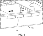
- FIG. 9 shows particular details of a slide strip 190 .
- a slide strip 190 mounted to each of the parallel frame members 102 a , 102 b , preferably on an exterior side, facing outwardly away from the longitudinal axis of the hoist frame 102 , to protect the parallel frame members 102 a , 102 b from destructive contact with the interchangeable body 104 .
- the slide strip 190 is preferably a flat strip affixed to the frame members 102 a , 102 b .
- the slide strips 190 are greaseless slide strips formed of a low friction material to support the interchangeable vehicle body during movement along the hoist.
- the slide strips 190 are formed of Nylatron, reducing wear and tear on the system.
- the slide strips 190 (and other Nylatron and other polymer parts described herein) reduce metal-on-metal contact between the hoist system 100 and the interchangeable bodies 104 , which can expose bare metal to the elements, causing rust, which can shorten the useful life of the hoist system 100 .
- the Nylatron slide strips 190 can be replaced when worn out, further extending the useful life of the hoist system 100 .
- FIGS. 2, 3 , and the details and rear views of FIGS. 10, 11, and 13 show particular details of body hold downs in the form of side channels 200 a , 200 b .
- the side channel body hold downs 200 a , 200 b are hooked structures having a generally C-shaped cross section having upper portions 202 a , 202 b configured to receive and retainably engage mating components 210 formed on an interchangeable body 104 .
- Each of the body hold downs 200 a , 200 b are mounted to each of the respective parallel frame members 102 a , 102 b , preferably on the respective exterior sides, facing outwardly away from the longitudinal axis of the hoist frame 102 .
- the C-shaped cross section with resulting upper portions 202 a , 202 b are sufficiently large to engage a variety of different sized mating components 210 associated with a variety of different sized interchangeable vehicle bodies 104 , and thereby enable a variety of different sized interchangeable vehicle bodies to be used on the hoist.
- the side channels 200 a , 200 b cooperate with slide pads 212 in the form of metal brackets each having an upward-facing surface including a Nylatron pad that are attached to the first and second parallel frame members 102 a , 102 b .
- the interchangeable body 104 rides within the body hold downs 200 a , 200 b , which keep the body 104 aligned and supported.
- the body 104 does not contact the body hold downs 200 a , 200 b but allows a clearance of approximately 1 ⁇ 8-inch, as shown in FIG. 11 .
- a body 104 When a body 104 is fully loaded, it rests upon the body hold downs 200 a , 200 b , which support the body 104 in the event of a rollover, thereby providing additional safety.
- the frame members 102 a , 102 b can include a support section 220 that provides a piping support for piping 222 , as can also be seen in FIG. 3 .
- the piping 222 provides hydraulic oil to the hydraulic winch motor 142 . It is appreciated in the art that using a hydraulic winch motor is a lower volume option that is needed for certain applications because it has a much greater duty cycle. However, it is to be appreciated that other types of winch motors 142 such as electric motors can alternatively be employed without departing from the invention.
Abstract
Description
Claims (14)
Priority Applications (8)
| Application Number | Priority Date | Filing Date | Title |
|---|---|---|---|
| US16/808,610 US11214186B2 (en) | 2020-03-04 | 2020-03-04 | Hoist for vehicle with interchangeable body |
| CA3170428A CA3170428A1 (en) | 2020-03-04 | 2021-03-01 | Hoist for vehicle with interchangeable body |
| MX2022010837A MX2022010837A (en) | 2020-03-04 | 2021-03-01 | Hoist for vehicle with interchangeable body. |
| PCT/US2021/020281 WO2021178308A1 (en) | 2020-03-04 | 2021-03-01 | Hoist for vehicle with interchangeable body |
| US17/895,374 US20220402422A1 (en) | 2020-03-04 | 2022-08-25 | Hoist for vehicle with interchangeable body |
| US18/081,291 US11833952B2 (en) | 2020-03-04 | 2022-12-14 | Hoist for vehicle with interchangeable body |
| US18/481,037 US20240025327A1 (en) | 2020-03-04 | 2023-10-04 | Hoist for vehicle with interchangeable body |
| US18/394,863 US20240123891A1 (en) | 2020-03-04 | 2023-12-22 | Hoist for vehicle with interchangeable body |
Applications Claiming Priority (1)
| Application Number | Priority Date | Filing Date | Title |
|---|---|---|---|
| US16/808,610 US11214186B2 (en) | 2020-03-04 | 2020-03-04 | Hoist for vehicle with interchangeable body |
Related Child Applications (1)
| Application Number | Title | Priority Date | Filing Date |
|---|---|---|---|
| PCT/US2021/020281 Continuation WO2021178308A1 (en) | 2020-03-04 | 2021-03-01 | Hoist for vehicle with interchangeable body |
Publications (2)
| Publication Number | Publication Date |
|---|---|
| US20210276475A1 US20210276475A1 (en) | 2021-09-09 |
| US11214186B2 true US11214186B2 (en) | 2022-01-04 |
Family
ID=77555389
Family Applications (5)
| Application Number | Title | Priority Date | Filing Date |
|---|---|---|---|
| US16/808,610 Active 2040-03-07 US11214186B2 (en) | 2020-03-04 | 2020-03-04 | Hoist for vehicle with interchangeable body |
| US17/895,374 Abandoned US20220402422A1 (en) | 2020-03-04 | 2022-08-25 | Hoist for vehicle with interchangeable body |
| US18/081,291 Active US11833952B2 (en) | 2020-03-04 | 2022-12-14 | Hoist for vehicle with interchangeable body |
| US18/481,037 Pending US20240025327A1 (en) | 2020-03-04 | 2023-10-04 | Hoist for vehicle with interchangeable body |
| US18/394,863 Pending US20240123891A1 (en) | 2020-03-04 | 2023-12-22 | Hoist for vehicle with interchangeable body |
Family Applications After (4)
| Application Number | Title | Priority Date | Filing Date |
|---|---|---|---|
| US17/895,374 Abandoned US20220402422A1 (en) | 2020-03-04 | 2022-08-25 | Hoist for vehicle with interchangeable body |
| US18/081,291 Active US11833952B2 (en) | 2020-03-04 | 2022-12-14 | Hoist for vehicle with interchangeable body |
| US18/481,037 Pending US20240025327A1 (en) | 2020-03-04 | 2023-10-04 | Hoist for vehicle with interchangeable body |
| US18/394,863 Pending US20240123891A1 (en) | 2020-03-04 | 2023-12-22 | Hoist for vehicle with interchangeable body |
Country Status (4)
| Country | Link |
|---|---|
| US (5) | US11214186B2 (en) |
| CA (1) | CA3170428A1 (en) |
| MX (1) | MX2022010837A (en) |
| WO (1) | WO2021178308A1 (en) |
Cited By (1)
| Publication number | Priority date | Publication date | Assignee | Title |
|---|---|---|---|---|
| US20230114428A1 (en) * | 2020-03-04 | 2023-04-13 | Deist Industries, Inc. | Hoist for vehicle with interchangeable body |
Families Citing this family (2)
| Publication number | Priority date | Publication date | Assignee | Title |
|---|---|---|---|---|
| SE541628C2 (en) * | 2018-03-06 | 2019-11-19 | Scania Cv Ab | A drive module for a vehicle and a vehicle assembled from a set of modules |
| CN216861591U (en) * | 2022-02-25 | 2022-07-01 | 三一重型装备有限公司 | Rear tailstock assembly, frame and operation machine |
Citations (30)
| Publication number | Priority date | Publication date | Assignee | Title |
|---|---|---|---|---|
| US1269265A (en) | 1917-09-25 | 1918-06-11 | William T Duggan | Interchangeable and removable truck-body. |
| US1633515A (en) * | 1926-03-04 | 1927-06-21 | Nat Grave Vault Co | Self-dumping truck |
| US2665020A (en) * | 1950-11-08 | 1954-01-05 | Charles E Whittle | Self-loading and unloading vehicle for palletized loads |
| US2789715A (en) | 1955-05-16 | 1957-04-23 | John W Filipoff | Interchangeable truck body |
| US3606059A (en) * | 1969-12-15 | 1971-09-20 | Herbert Haberle Jr | Roll-off trailer |
| US4015879A (en) * | 1976-02-26 | 1977-04-05 | Shonkwiler Forest M | Convertible adjustable tilting bed for vehicles |
| US4750855A (en) | 1986-10-20 | 1988-06-14 | Anderson Leonard E | Retrofittable vehicle framework means and method for interchangeable use with a variety of attachment units |
| KR900018596A (en) | 1989-05-08 | 1990-12-22 | 티모티 엔. 비숍 | Combustion method and apparatus for spraying oxidant in multiple |
| US4986719A (en) * | 1986-03-03 | 1991-01-22 | Galbreath Incorporated | Roll-off hoist for variable positioning of containers |
| US5133633A (en) * | 1990-11-21 | 1992-07-28 | Jerr-Dan Corp. | Low-angle slidably supported roll-back vehicle transport apparatus |
| US5169194A (en) * | 1989-07-12 | 1992-12-08 | Kyokuto Kaihatsu Kogyo Co., Ltd. | Container carrier |
| JPH06336137A (en) | 1993-05-28 | 1994-12-06 | Tech Res & Dev Inst Of Japan Def Agency | Transport vehicle for bridge node |
| US5405233A (en) * | 1993-05-20 | 1995-04-11 | Cordell; Steven R. | Dumpster handling system |
| US5829946A (en) | 1995-01-24 | 1998-11-03 | Mcneilus Truck And Manufacturing, Inc. | Detachable truck body and handling mechanism |
| US6120234A (en) * | 1991-02-12 | 2000-09-19 | Dinverno; Daniel | Van-mounted service carts for skilled tradesmen and ramp mechanisms for use with the same |
| WO2001038136A1 (en) | 1999-11-23 | 2001-05-31 | Albert Kirk Jacob | Multi-task truck |
| US6409275B1 (en) | 2000-05-02 | 2002-06-25 | The Heil Company | Frame attachment for vehicle |
| US6413033B1 (en) | 2000-01-10 | 2002-07-02 | Jamie Monroig, Jr. | Cargo carrier for vehicle |
| US6431577B1 (en) | 2001-06-20 | 2002-08-13 | Jeffrey L Chapman | Trailer hitch support body |
| US6647896B1 (en) * | 2002-01-14 | 2003-11-18 | Ysd Industries, Inc. | Greaseless hanger assembly for a railcar door |
| US7037062B2 (en) | 2001-05-08 | 2006-05-02 | On-Trux Limited | Truck having an extendable and retractable truck bed to receive truck boxes of different lengths and method of operation thereof |
| US7096963B2 (en) * | 2004-02-26 | 2006-08-29 | Devin International, Inc. | Swing arm crane and method |
| US7357457B2 (en) | 2004-11-02 | 2008-04-15 | Thomas Quick Change, Llc | Vehicle with interchangeable truck bed |
| US20080112786A1 (en) | 2001-05-14 | 2008-05-15 | Deist Industries, Inc. D/B/A Buck's Fabricating | Hoist for loading and unloading objects on a truck bed |
| US20100101119A1 (en) * | 2008-10-27 | 2010-04-29 | Andrew Roberts | Quick-attach secondary lift mechanism for snowplows |
| US8393686B2 (en) * | 2008-07-24 | 2013-03-12 | Gladiator Equipment LLC | Hoist employing a multiple piston cylinder |
| US20160280114A1 (en) | 2015-03-26 | 2016-09-29 | Robert C. Baxter, Jr. | Method and apparatus for the transportation of sporting and recreational equipment on a vehicle |
| US10029603B2 (en) | 2015-07-27 | 2018-07-24 | NR-LOK, Corp. | Interchangeable truck bed |
| EP2946970B1 (en) | 2014-05-21 | 2019-07-10 | Pris-Mag S.r.l. | Truck provided with an apparatus for moving bodies |
| US20200307435A1 (en) * | 2019-03-29 | 2020-10-01 | Wastequip, Llc | Hoist Apparatus Securement System and Method |
Family Cites Families (14)
| Publication number | Priority date | Publication date | Assignee | Title |
|---|---|---|---|---|
| US100296A (en) | 1870-03-01 | Ments to samuel b | ||
| US582994A (en) | 1897-05-18 | Hook-and-eye holder for sewing-machines | ||
| US126926A (en) | 1872-05-21 | Improvement in filters | ||
| US278971A (en) | 1883-06-05 | Vehicle-spring | ||
| US475085A (en) | 1892-05-17 | Type-writing machine | ||
| US643157A (en) | 1899-03-20 | 1900-02-13 | Roland Rakestraw | Gate. |
| US640927A (en) | 1899-06-26 | 1900-01-09 | Robert Mitchell Jr | Shielded rubber tire for vehicles. |
| US703706A (en) | 1901-11-23 | 1902-07-01 | John August Meyer | Crude-oil burner. |
| US735745A (en) | 1903-01-14 | 1903-08-11 | George A Fredenburgh | Thread-dressing machine. |
| KR910007882Y1 (en) * | 1989-04-12 | 1991-10-07 | 현대자동차 주식회사 | Vehicle adapted for load transproation |
| US5836657A (en) * | 1996-05-01 | 1998-11-17 | Omaha Standard, Inc. | Detachable stabilized intermodal container dumping apparatus |
| US6789829B1 (en) * | 2003-02-28 | 2004-09-14 | Cory S. Kapels | Lift and dump bed |
| US7090305B2 (en) * | 2004-04-08 | 2006-08-15 | Stealth Dump Trucks, Inc. | Vehicle dump body elevation device, kit, and method relating thereto |
| US11214186B2 (en) * | 2020-03-04 | 2022-01-04 | Deist Industries, Inc. | Hoist for vehicle with interchangeable body |
-
2020
- 2020-03-04 US US16/808,610 patent/US11214186B2/en active Active
-
2021
- 2021-03-01 WO PCT/US2021/020281 patent/WO2021178308A1/en active Application Filing
- 2021-03-01 MX MX2022010837A patent/MX2022010837A/en unknown
- 2021-03-01 CA CA3170428A patent/CA3170428A1/en active Pending
-
2022
- 2022-08-25 US US17/895,374 patent/US20220402422A1/en not_active Abandoned
- 2022-12-14 US US18/081,291 patent/US11833952B2/en active Active
-
2023
- 2023-10-04 US US18/481,037 patent/US20240025327A1/en active Pending
- 2023-12-22 US US18/394,863 patent/US20240123891A1/en active Pending
Patent Citations (30)
| Publication number | Priority date | Publication date | Assignee | Title |
|---|---|---|---|---|
| US1269265A (en) | 1917-09-25 | 1918-06-11 | William T Duggan | Interchangeable and removable truck-body. |
| US1633515A (en) * | 1926-03-04 | 1927-06-21 | Nat Grave Vault Co | Self-dumping truck |
| US2665020A (en) * | 1950-11-08 | 1954-01-05 | Charles E Whittle | Self-loading and unloading vehicle for palletized loads |
| US2789715A (en) | 1955-05-16 | 1957-04-23 | John W Filipoff | Interchangeable truck body |
| US3606059A (en) * | 1969-12-15 | 1971-09-20 | Herbert Haberle Jr | Roll-off trailer |
| US4015879A (en) * | 1976-02-26 | 1977-04-05 | Shonkwiler Forest M | Convertible adjustable tilting bed for vehicles |
| US4986719A (en) * | 1986-03-03 | 1991-01-22 | Galbreath Incorporated | Roll-off hoist for variable positioning of containers |
| US4750855A (en) | 1986-10-20 | 1988-06-14 | Anderson Leonard E | Retrofittable vehicle framework means and method for interchangeable use with a variety of attachment units |
| KR900018596A (en) | 1989-05-08 | 1990-12-22 | 티모티 엔. 비숍 | Combustion method and apparatus for spraying oxidant in multiple |
| US5169194A (en) * | 1989-07-12 | 1992-12-08 | Kyokuto Kaihatsu Kogyo Co., Ltd. | Container carrier |
| US5133633A (en) * | 1990-11-21 | 1992-07-28 | Jerr-Dan Corp. | Low-angle slidably supported roll-back vehicle transport apparatus |
| US6120234A (en) * | 1991-02-12 | 2000-09-19 | Dinverno; Daniel | Van-mounted service carts for skilled tradesmen and ramp mechanisms for use with the same |
| US5405233A (en) * | 1993-05-20 | 1995-04-11 | Cordell; Steven R. | Dumpster handling system |
| JPH06336137A (en) | 1993-05-28 | 1994-12-06 | Tech Res & Dev Inst Of Japan Def Agency | Transport vehicle for bridge node |
| US5829946A (en) | 1995-01-24 | 1998-11-03 | Mcneilus Truck And Manufacturing, Inc. | Detachable truck body and handling mechanism |
| WO2001038136A1 (en) | 1999-11-23 | 2001-05-31 | Albert Kirk Jacob | Multi-task truck |
| US6413033B1 (en) | 2000-01-10 | 2002-07-02 | Jamie Monroig, Jr. | Cargo carrier for vehicle |
| US6409275B1 (en) | 2000-05-02 | 2002-06-25 | The Heil Company | Frame attachment for vehicle |
| US7037062B2 (en) | 2001-05-08 | 2006-05-02 | On-Trux Limited | Truck having an extendable and retractable truck bed to receive truck boxes of different lengths and method of operation thereof |
| US20080112786A1 (en) | 2001-05-14 | 2008-05-15 | Deist Industries, Inc. D/B/A Buck's Fabricating | Hoist for loading and unloading objects on a truck bed |
| US6431577B1 (en) | 2001-06-20 | 2002-08-13 | Jeffrey L Chapman | Trailer hitch support body |
| US6647896B1 (en) * | 2002-01-14 | 2003-11-18 | Ysd Industries, Inc. | Greaseless hanger assembly for a railcar door |
| US7096963B2 (en) * | 2004-02-26 | 2006-08-29 | Devin International, Inc. | Swing arm crane and method |
| US7357457B2 (en) | 2004-11-02 | 2008-04-15 | Thomas Quick Change, Llc | Vehicle with interchangeable truck bed |
| US8393686B2 (en) * | 2008-07-24 | 2013-03-12 | Gladiator Equipment LLC | Hoist employing a multiple piston cylinder |
| US20100101119A1 (en) * | 2008-10-27 | 2010-04-29 | Andrew Roberts | Quick-attach secondary lift mechanism for snowplows |
| EP2946970B1 (en) | 2014-05-21 | 2019-07-10 | Pris-Mag S.r.l. | Truck provided with an apparatus for moving bodies |
| US20160280114A1 (en) | 2015-03-26 | 2016-09-29 | Robert C. Baxter, Jr. | Method and apparatus for the transportation of sporting and recreational equipment on a vehicle |
| US10029603B2 (en) | 2015-07-27 | 2018-07-24 | NR-LOK, Corp. | Interchangeable truck bed |
| US20200307435A1 (en) * | 2019-03-29 | 2020-10-01 | Wastequip, Llc | Hoist Apparatus Securement System and Method |
Cited By (2)
| Publication number | Priority date | Publication date | Assignee | Title |
|---|---|---|---|---|
| US20230114428A1 (en) * | 2020-03-04 | 2023-04-13 | Deist Industries, Inc. | Hoist for vehicle with interchangeable body |
| US11833952B2 (en) * | 2020-03-04 | 2023-12-05 | Deist Industries, Inc. | Hoist for vehicle with interchangeable body |
Also Published As
| Publication number | Publication date |
|---|---|
| US20230114428A1 (en) | 2023-04-13 |
| US20240025327A1 (en) | 2024-01-25 |
| US20210276475A1 (en) | 2021-09-09 |
| US11833952B2 (en) | 2023-12-05 |
| CA3170428A1 (en) | 2021-09-10 |
| US20240123891A1 (en) | 2024-04-18 |
| WO2021178308A1 (en) | 2021-09-10 |
| US20220402422A1 (en) | 2022-12-22 |
| MX2022010837A (en) | 2022-11-10 |
Similar Documents
| Publication | Publication Date | Title |
|---|---|---|
| US11214186B2 (en) | Hoist for vehicle with interchangeable body | |
| US8414091B2 (en) | Track tensioning system for mobile vehicles, including lift cranes | |
| US4645405A (en) | Roll-off container handling mechanism | |
| US10308158B2 (en) | Utility trailer with movable bed | |
| US8152435B2 (en) | Flatbed tow truck pivoting platform assembly and method of use | |
| CA2677660A1 (en) | Mechanically-driven flip axle assembly and method of making | |
| US10017095B2 (en) | Mobile support and lift system | |
| US20150343937A1 (en) | Flatbed Tow Truck Assembly And Method Of Use | |
| US20080253853A1 (en) | Attachment Device for Moving Cargo Containers | |
| KR101843011B1 (en) | Multi-purpose loader | |
| AU2005201054A1 (en) | Payload container for a work machine | |
| US5403061A (en) | Control system for hinged body vehicles | |
| US20100231025A1 (en) | Adjustable crawler vehicle | |
| RU2264347C2 (en) | Crane-manipulator plant | |
| JP2016002953A (en) | Load-carrying platform for transportation vehicle and dump truck loaded with this load-carrying platform | |
| US7963535B2 (en) | Tag axle pivot mount | |
| US11285899B2 (en) | Guard assembly | |
| CN114585537A (en) | Safety assembly for off-highway trucks | |
| JP6231476B2 (en) | Vehicle body including curved metal plate floor | |
| WO2016028716A1 (en) | Flatbed tow truck assembly and method of use | |
| CN210760990U (en) | Detachable frame body of rear frame of underground transport vehicle | |
| CN220742829U (en) | Rear lifting tail plate for carriage | |
| US20220219591A1 (en) | Roll Off Truck | |
| KR102650358B1 (en) | Multi-purpose loader | |
| CN108341344B (en) | Hoisting mechanism and container with same |
Legal Events
| Date | Code | Title | Description |
|---|---|---|---|
| FEPP | Fee payment procedure |
Free format text: ENTITY STATUS SET TO UNDISCOUNTED (ORIGINAL EVENT CODE: BIG.); ENTITY STATUS OF PATENT OWNER: SMALL ENTITY |
|
| FEPP | Fee payment procedure |
Free format text: ENTITY STATUS SET TO SMALL (ORIGINAL EVENT CODE: SMAL); ENTITY STATUS OF PATENT OWNER: SMALL ENTITY |
|
| STPP | Information on status: patent application and granting procedure in general |
Free format text: RESPONSE TO NON-FINAL OFFICE ACTION ENTERED AND FORWARDED TO EXAMINER |
|
| STPP | Information on status: patent application and granting procedure in general |
Free format text: NOTICE OF ALLOWANCE MAILED -- APPLICATION RECEIVED IN OFFICE OF PUBLICATIONS |
|
| AS | Assignment |
Owner name: DEIST INDUSTRIES, INC., PENNSYLVANIA Free format text: ASSIGNMENT OF ASSIGNORS INTEREST;ASSIGNORS:BURNS, JEFFREY M.;SCHUMACHER, ANDREW;SIGNING DATES FROM 20211102 TO 20211115;REEL/FRAME:058224/0959 |
|
| STPP | Information on status: patent application and granting procedure in general |
Free format text: PUBLICATIONS -- ISSUE FEE PAYMENT VERIFIED |
|
| AS | Assignment |
Owner name: DEIST INDUSTRIES, INC., PENNSYLVANIA Free format text: ASSIGNMENT OF ASSIGNORS INTEREST;ASSIGNOR:BURNS, JEFFREY M.;REEL/FRAME:058567/0837 Effective date: 20211115 Owner name: DEIST INDUSTRIES, INC., PENNSYLVANIA Free format text: ASSIGNMENT OF ASSIGNORS INTEREST;ASSIGNOR:SCHUMACHER, ANDREW;REEL/FRAME:058254/0431 Effective date: 20211102 |
|
| STCF | Information on status: patent grant |
Free format text: PATENTED CASE |
|
| AS | Assignment |
Owner name: FSC COBBLER LLC, ILLINOIS Free format text: ASSIGNMENT OF ASSIGNORS INTEREST;ASSIGNOR:DEIST INDUSTRIES, INC.;REEL/FRAME:058526/0639 Effective date: 20211230 |
|
| AS | Assignment |
Owner name: DEIST INDUSTRIES, LLC, ILLINOIS Free format text: CHANGE OF NAME;ASSIGNOR:FSC COBBLER LLC;REEL/FRAME:060221/0470 Effective date: 20211230 |