EP0439317A2 - Plaquette à fileter - Google Patents
Plaquette à fileter Download PDFInfo
- Publication number
- EP0439317A2 EP0439317A2 EP91300457A EP91300457A EP0439317A2 EP 0439317 A2 EP0439317 A2 EP 0439317A2 EP 91300457 A EP91300457 A EP 91300457A EP 91300457 A EP91300457 A EP 91300457A EP 0439317 A2 EP0439317 A2 EP 0439317A2
- Authority
- EP
- European Patent Office
- Prior art keywords
- insert
- arm
- sides
- tool holder
- locating
- Prior art date
- Legal status (The legal status is an assumption and is not a legal conclusion. Google has not performed a legal analysis and makes no representation as to the accuracy of the status listed.)
- Granted
Links
Images


Classifications
-
- B—PERFORMING OPERATIONS; TRANSPORTING
- B23—MACHINE TOOLS; METAL-WORKING NOT OTHERWISE PROVIDED FOR
- B23G—THREAD CUTTING; WORKING OF SCREWS, BOLT HEADS, OR NUTS, IN CONJUNCTION THEREWITH
- B23G5/00—Thread-cutting tools; Die-heads
- B23G5/18—Milling cutters
-
- B—PERFORMING OPERATIONS; TRANSPORTING
- B23—MACHINE TOOLS; METAL-WORKING NOT OTHERWISE PROVIDED FOR
- B23B—TURNING; BORING
- B23B27/00—Tools for turning or boring machines; Tools of a similar kind in general; Accessories therefor
- B23B27/06—Profile cutting tools, i.e. forming-tools
- B23B27/065—Thread-turning tools
-
- B—PERFORMING OPERATIONS; TRANSPORTING
- B23—MACHINE TOOLS; METAL-WORKING NOT OTHERWISE PROVIDED FOR
- B23B—TURNING; BORING
- B23B27/00—Tools for turning or boring machines; Tools of a similar kind in general; Accessories therefor
- B23B27/14—Cutting tools of which the bits or tips or cutting inserts are of special material
- B23B27/16—Cutting tools of which the bits or tips or cutting inserts are of special material with exchangeable cutting bits or cutting inserts, e.g. able to be clamped
- B23B27/1625—Cutting tools of which the bits or tips or cutting inserts are of special material with exchangeable cutting bits or cutting inserts, e.g. able to be clamped with plate-like cutting inserts of special shape clamped by a clamping member acting almost perpendicularly on the chip-forming plane
-
- B—PERFORMING OPERATIONS; TRANSPORTING
- B23—MACHINE TOOLS; METAL-WORKING NOT OTHERWISE PROVIDED FOR
- B23B—TURNING; BORING
- B23B2200/00—Details of cutting inserts
- B23B2200/04—Overall shape
- B23B2200/048—Star form
-
- B—PERFORMING OPERATIONS; TRANSPORTING
- B23—MACHINE TOOLS; METAL-WORKING NOT OTHERWISE PROVIDED FOR
- B23B—TURNING; BORING
- B23B2205/00—Fixation of cutting inserts in holders
- B23B2205/12—Seats for cutting inserts
Definitions
- High quality threads are commonly cut in a workpiece mounted on a lathe, by a threading insert that is held in a tool holder.
- the cutting edge of the insert has a limited life, such as 50 threads per cutting edge, and the life of the insert is increased by constructing it with multiple cutting edges.
- the insert is removed and reinstalled with a new cutting edge in position, it being highly desirable that the new cutting edge lie precisely in the same position as the old edge, despite the change in insert position.
- the manufacturing cost for an insert is about the same no matter how many cutting edges it has, so it is desirable that each insert have as many cutting edges as possible.
- any insert to be practical, has to allow rapid and highly precise reinstallation of the insert to present a new cutting edge, with the insert and the tool holder being of simple and rugged design. It is also desirable if the insert can be used to cut an internal thread in a hole of small diameter, as well as an external thread.
- U.S. Patent 3,613,197 by Stier describes a threading insert with eight cutting edges.
- His insert includes a mount portion with a screw-receiving hole for mounting on a tool holder, and four arms radiating from the mount portion, with each arm having two cutting edges.
- he precisely locates his insert on a tool holder by using locating surfaces along the opposite sides of each arm.
- the sides of his arms are long, resulting in only a small thickness of metal between the innermost locations on his arms and the central hole of the insert,
- the chips generated during cutting ride along a long flat surface into a narrow area, resulting in "balling" up of the chips.
- a threading insert which provided many cutting edges, which was of sturdy construction and could be precisely mounted on a tool holder of simple construction, would be of considerable value.
- a threading insert which has multiple cutting edges in a construction that is strong and that enables precise holding on a relatively low cost tool holder.
- the insert has a mount portion with a through hole lying on its axis for receiving a fastener that holds the insert to a tool holder, and has a plurality of arms radiating from the mount portion.
- Each arm has a radially outer edge and has opposite sides.
- the mount portion forms a flat locating surface at the periphery of the insert, with each flat locating surface lying between a pair of arms. In an insert with four arms, the flat locating surfaces lie on the surfaces of an imaginary square.
- each flat locating surface and an arm side is preferably closely spaced from an adjacent cutting edge and forms an obtuse angle.
- the arms are preferably relatively narrow, with the outer edges of all arms subtending a total angle not more than about one third of a circle, or 120°.
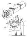
- Fig. 1 illustrates a threading tool apparatus or tool 10 which includes a threading insert 12 mounted on a tool holder 14.
- the tool holder includes a bar 16 and a replaceable pocket wedge 20 that is mounted by bolts 22 on the bar and which has a recess 23 that receives the insert 12 and that supports it.
- the threading insert includes a mount portion 24 with an axis 26 and with a through hole 30 lying on the axis.
- a fastener 32 such as an Allen screw passes through the hole and is threadably joined to a hole in the tool holder 14 to hold face 12F of the insert against face 16F of the bar 16 closing the recess 23.
- the insert also has arms 34-40 that radiate from the mount portion 24 of the insert and which form cutting edges 42. The cutting edges 42 are all formed to cut threads in a workpiece.
- the mount portion 24 of the insert forms four flat locating surfaces 42-48 at the periphery of the insert, thus shown straight in section, and each locating surface such as 44 is shown lying between a pair of arms 34, 36.
- the locating surfaces 42-48 lie on the sides of an imaginary square 50 (a polygon with four equal sides).
- Each arm such as 34 has a radially outer edge 52 and has first and second opposite sides 54, 56.
- the outer edge 52 has opposite ends and forms a first cutting edge 58 at the intersection of the first side 54 and the outer edge, and a second cutting edge 60 at the intersection of the second side 56 and the outer side.
- the insert forms eight cutting edges that are useful for cutting a thread in a workpiece.
- the insert is mounted on the wedge 20 of the tool holder, with a cutting edge 58 projecting from a tool holder end 14E to cut a thread.
- the cutting edge 58 of arm 34 is uppermost and the opposite cutting edge 60 is lowermost.
- the first or upper side 54 is oriented horizontally, so that an extension of it passes through the axis of rotation of the workpiece which is held in a lathe.
- the outer edge 52 (or at least the portion immediately under the cutting edge) extends at an angle A of about 12-15° from the vertical, to provide a clearance angle that is necessary for efficient machining.
- the insert is located at a precise location on the wedge 20 of the tool holder by two flat positioning surfaces 62 , 64 of the wedge that engage corresponding flat locating surfaces 44, 46 on the mount portion of the insert.
- Another positioning surface 66 is formed on a clamp 70 which can be operated to press the locating surface 48 on the insert against the opposite positioning surface 62 on the wedge, as by turning a clamp tightening screw 72.
- the tool holder holds the insert at a helix angle of 1.5° (depending on the relationship of thread pitch to workpiece diameter) to insure that the insert form is parallel to the helical thread.
- the fastener 32 is removed and the clamp 70 loosened, to allow the insert to be removed.
- the insert is reinstalled with a cutting edge such as 74 of another arm 40 positioned where the cutting edge 58 of arm 34 was previously located. After four cutting edges have been worn, the next time the insert is removed it is flipped over so that its face 76 that previously faced away from the tool holder, now lies adjacent to the tool holder, so that four additional edges such as 60 can be used.
- the insert is sufficiently precise to allow a new cutting edge to lie within 0.0127 inch of the preceding one, which minimizes down time on CNC equipment.
- the insert 12 is formed with high precision, as by pressing particles of a hard material such as silicon carbide into a die and later sintering it.
- the wedge 20 is constructed with its two positioning surfaces 62, 64 lying precisely perpendicular to one another.
- the insert 12 is installed on the wedge 20 by positioning the insert so two of its locating surfaces such as 44, 46 lie against the positioning surfaces 62, 64.
- the clamp 70 is then tightened. It is not necessary that the clamp positioning surface 66 be precise, as its only function is to press the insert against the positioning surface 62. After the insert is clamped, the fastener 32 is tightened. It may be noted that it is not necessary to clamp the insert against the locating surface 64, as forces encountered during threading keep the insert pressed against the positioning surface 46.
- the wedge has a cutout 80 for receiving one of the insert arms, without making contact with either the outer edge or either side of the arm.
- the wedge 20 has only two precision surfaces, these being the positioning surfaces 62 and 64. These surfaces are easy to machine because they are both flat and precisely perpendicular to one another. For the same reason, it is easy to check the position of these surfaces, as by holding a machine square to them.
- the pocket wedge is a replaceable item, that is replaced by loosening the wedge bolts 22. After replacement of a wedge, the machine controls that are used to position the threading tool may have to be readjusted and measured. It is also common to not use a replacement pocket wedge, but instead to machine the bar 16 to directly hold the insert. It may be noted that with a working upper cutting edge at 58, the opposite or lower edge 60 of the arm is left unsupported, by leaving a space 82 below it.
- each cutting edge such as 74 generally has a largely V-shaped outer part 86 (except when cutting square threads or the like) and has a pair of finishing sides 90, 92).
- the cutting edges of this insert are useful for cutting a thread 94 in a workpiece 96, where the thread has a predetermined depth B.
- the insert is in the form of a plate 100 with opposite faces 76, 102, and is formed symmetrically about a central plane 104 of the plate.
- Fig. 5 shows the insert 12 cutting a thread in a workpiece 96, with the cutting edge 58 having cut to about half the depth of the final thread.
- the cutting operation generates a chip 106 which passes along the upper side 54 of the arm and onto the flat locating surface 50, the chip breaking at about the point 108 and falling off the insert.
- the insert has a transition 110 where the arm side 54 merges with the locating surface 50, which is of a small radius of curvature C and which has a center or intersection at the point 112.
- the angle D between a side of the arm and an adjacent flat surface is preferably more than 90° in order to prevent the chip from curling up and creating a ball of chips at the intersection.
- the angle D is preferably less than 180° to cause curvature in the chip so as to stress it and cause early breakage of the chip.
- the distance E between a finishing side 90 and the intersection 112 is preferably small, preferably less than the height B of the thread.
- the locating surface 50 is long and lies a considerable distance F from the axis 26 of the insert.
- this long distance F results in the insert having a considerable thickness G between the hole 30 and an adjacent locating surface such as 44, which minimizes the possibility of cracking of the insert.
- the long locating surface facilitates secure positioning of the insert to resist turning due to the forces encountered during thread cutting.
- the distance F is preferably more than half the distance H between the axis of the insert and an outer edge, such as 52.
- each arm preferably has a relatively small width J so it subtends a relatively small angle K.
- the angle K is preferably no more than about 30° (i.e. less than 10% more, or in other words less than 33°). This results in long locating surfaces 50 between the arms. Also, this allows the insert to be used for internal threading in a hole of relatively small size.
- the total angle subtended by all arms is preferably no more than about one third of a full circle. It can be seen that the opposite sides 54, 56 of an arm 34 diverge in a radially outward direction (away from axis 26).
- One insert applicant has designed, of the type shown in Figures 1-5, has a width 2H of 0.745 inch (about 19mm), a plate thickness of 0.171 inch (about 4.34mm), and locating surfaces lying in a square having sides 2F of 0.460 inch (about 11.7mm).
- the angle K was equal to 28° and the width J of the outer edge of each arm was 0.190 inch (about 4.8mm).
- the radius C of each transition was 0.050 inch (about 1.27mm) and the distance E between a finishing side and the intersection 112 was about 0.050 inch (about 1.27mm).
- the outer diameter L of the hole 30 was 0.232D (about 5.9mm).
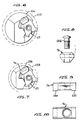
- Fig. 6 illustrates the insert 12 being used on an internal tool holder 120 to cut a thread in a hole 122 in a workpiece.
- Fig. 7 illustrates the insert 12 on another internal tool holder 126 which is designed to enable the insert to be used to thread a smaller diameter hole 128.
- Figs. 8-10 illustrate details of the clamp 70 which is used to clamp the insert in the tool holder of Figs. 1, 6, or 7.
- One end 130 of the clamp presses down against a locating surface on the insert, the opposite end 132 presses down against the tool holder and a screw 134 screws the clamp down to the tool holder.
- the wedge 20 is slightly thinner than the insert 12.
- the insert face 102 presses against a flat face 136 of the bar 16.
- the bar surface 136 is angled by about 1 1/2° (38mm) to 2 1/2° (63.5mm) from the vertical to follow the helix of a thread.
- Applicant mounts about forty wedge blanks in the vise of a milling machine, machines the cutouts 80 of all wedges in the stack, and then precision grinds the positioning surfaces 62, 64 of all forty blanks in a stack.
- the grinding wheel is dressed, and then grinds both surfaces 62, 64 at the same time, with the projecting corner of the grinding wheel lying in the cutout 80.
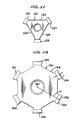
- Fig. 11 illustrates another insert 140 which uses the same general approach as for the insert of Fig. 3, except that the insert 140 has only three arms 141-143 to provide six cutting edges for threading.
- the insert 140 has three locating surfaces 144-146 lying on a regular (equal sides) polygon with three sides.
- Fig. 12 illustrates another insert 150 which has six arms 151-156 resulting in twelve cutting edges useful for threading.
- the ratio of the height L of each cutting edge to the distance M between each outer edge 160 and the axis 162 of the insert, is approximately the same as for the insert of Fig. 5.
- the six arms subtend an angle of one third of a circle, resulting in each outer edge 160 being shorter. This results in less material of the insert under each cutting edge, so that the setup is not as rigid as an insert with fewer arms.
- the insert can provide a threading insert having numerous cutting edges, and which can be mounted with high precision in a tool holder of low cost.
- the insert includes a mount portion having a plurality of flat sides lying on the sides of an imaginary polygon with sides of equal length, and arms radiating outwardly from the corners of the polygon.
- Each arm has an outer edge and opposite sides, and forms a cutting edge at the intersection of each arm side with the outer edge.
- the intersection of each arm side with a flat locating surface lies close to the cutting edge and there is an obtuse angle between each arm side and an adjacent flat locating surface.
- the total angle occupied by all arms is preferably no more than about one third of a full circle.
- the tool holder locates the insert on at least two of the flat locating surfaces, and does not support a side of an arm.
Landscapes
- Engineering & Computer Science (AREA)
- Mechanical Engineering (AREA)
- Cutting Tools, Boring Holders, And Turrets (AREA)
Applications Claiming Priority (2)
| Application Number | Priority Date | Filing Date | Title |
|---|---|---|---|
| US46856490A | 1990-01-23 | 1990-01-23 | |
| US468564 | 1990-01-23 |
Publications (3)
| Publication Number | Publication Date |
|---|---|
| EP0439317A2 true EP0439317A2 (fr) | 1991-07-31 |
| EP0439317A3 EP0439317A3 (en) | 1992-03-04 |
| EP0439317B1 EP0439317B1 (fr) | 1996-03-06 |
Family
ID=23860314
Family Applications (1)
| Application Number | Title | Priority Date | Filing Date |
|---|---|---|---|
| EP19910300457 Expired - Lifetime EP0439317B1 (fr) | 1990-01-23 | 1991-01-21 | Plaquette à fileter |
Country Status (4)
| Country | Link |
|---|---|
| EP (1) | EP0439317B1 (fr) |
| JP (1) | JPH06218626A (fr) |
| CA (1) | CA2034662C (fr) |
| DE (1) | DE69117544T2 (fr) |
Cited By (7)
| Publication number | Priority date | Publication date | Assignee | Title |
|---|---|---|---|---|
| EP0850715A1 (fr) * | 1996-12-31 | 1998-07-01 | Gebr. Heller Maschinenfabrik GmbH | Outil avec plaquette de coupe |
| EP2123378A1 (fr) * | 2008-05-20 | 2009-11-25 | VARGUS Ltd. | Support d'outil, bras et insert |
| WO2012052984A1 (fr) * | 2010-10-20 | 2012-04-26 | Iscar Ltd. | Outil de coupe et plaquette de coupe pour cet outil |
| CN103769635A (zh) * | 2012-10-19 | 2014-05-07 | 苹果公司 | 成形刀具 |
| EP2722122A4 (fr) * | 2011-06-17 | 2015-06-24 | Tungaloy Corp | Plaquette de coupe et outil de coupe rotatif |
| CN107186227A (zh) * | 2013-01-03 | 2017-09-22 | 伊斯卡有限公司 | 切削刀具及其具有正好三个切削部的切削镶块 |
| CN110405234A (zh) * | 2019-06-27 | 2019-11-05 | 株洲钻石切削刀具股份有限公司 | 一种具有粗精加工一体的多功能车削刀片及切削刀具 |
Families Citing this family (3)
| Publication number | Priority date | Publication date | Assignee | Title |
|---|---|---|---|---|
| IL152161A (en) * | 2002-02-19 | 2008-03-20 | Jacob Friedman | Metal cutting tool |
| EP2823921B1 (fr) * | 2012-03-08 | 2017-08-09 | Sumitomo Electric Hardmetal Corp. | Outil de coupe |
| US8714886B2 (en) * | 2012-06-19 | 2014-05-06 | Iscar, Ltd. | Threading cutting tool and double-sided indexable threading cutting insert therefor |
Citations (7)
| Publication number | Priority date | Publication date | Assignee | Title |
|---|---|---|---|---|
| US3613197A (en) * | 1970-03-09 | 1971-10-19 | Carmet Co | Threading insert |
| DE2052386A1 (de) * | 1970-10-26 | 1972-04-27 | Horn P | Schneidkörper, insbesondere für eine Werkzeugmaschine, und Verfahren zu seiner Herstellung |
| US3968549A (en) * | 1972-03-22 | 1976-07-13 | Allied Tool Products, Inc. | Cutting tool |
| GB1532238A (en) * | 1976-07-16 | 1978-11-15 | Diagrit Grinding Co Ltd | Turning tool |
| US4169690A (en) * | 1977-07-26 | 1979-10-02 | Kennametal Inc. | Cutting insert |
| GB2070472A (en) * | 1980-02-26 | 1981-09-09 | Brock & Co Ltd L & Ti | Disposable tool tip for cutting a screw-thread or groove |
| US4602897A (en) * | 1984-04-25 | 1986-07-29 | Iscar Metals, Inc. | Cutting insert and grooving cutter |
Family Cites Families (1)
| Publication number | Priority date | Publication date | Assignee | Title |
|---|---|---|---|---|
| JPH0650084Y2 (ja) * | 1986-04-21 | 1994-12-21 | 日本特殊陶業株式会社 | スローアウェイ式裏加工用切削工具 |
-
1991
- 1991-01-21 DE DE1991617544 patent/DE69117544T2/de not_active Expired - Fee Related
- 1991-01-21 CA CA 2034662 patent/CA2034662C/fr not_active Expired - Lifetime
- 1991-01-21 EP EP19910300457 patent/EP0439317B1/fr not_active Expired - Lifetime
- 1991-01-22 JP JP3005899A patent/JPH06218626A/ja active Pending
Patent Citations (7)
| Publication number | Priority date | Publication date | Assignee | Title |
|---|---|---|---|---|
| US3613197A (en) * | 1970-03-09 | 1971-10-19 | Carmet Co | Threading insert |
| DE2052386A1 (de) * | 1970-10-26 | 1972-04-27 | Horn P | Schneidkörper, insbesondere für eine Werkzeugmaschine, und Verfahren zu seiner Herstellung |
| US3968549A (en) * | 1972-03-22 | 1976-07-13 | Allied Tool Products, Inc. | Cutting tool |
| GB1532238A (en) * | 1976-07-16 | 1978-11-15 | Diagrit Grinding Co Ltd | Turning tool |
| US4169690A (en) * | 1977-07-26 | 1979-10-02 | Kennametal Inc. | Cutting insert |
| GB2070472A (en) * | 1980-02-26 | 1981-09-09 | Brock & Co Ltd L & Ti | Disposable tool tip for cutting a screw-thread or groove |
| US4602897A (en) * | 1984-04-25 | 1986-07-29 | Iscar Metals, Inc. | Cutting insert and grooving cutter |
Cited By (11)
| Publication number | Priority date | Publication date | Assignee | Title |
|---|---|---|---|---|
| EP0850715A1 (fr) * | 1996-12-31 | 1998-07-01 | Gebr. Heller Maschinenfabrik GmbH | Outil avec plaquette de coupe |
| EP2123378A1 (fr) * | 2008-05-20 | 2009-11-25 | VARGUS Ltd. | Support d'outil, bras et insert |
| WO2012052984A1 (fr) * | 2010-10-20 | 2012-04-26 | Iscar Ltd. | Outil de coupe et plaquette de coupe pour cet outil |
| US8678718B2 (en) | 2010-10-20 | 2014-03-25 | Iscar, Ltd. | Cutting tool and cutting insert therefor |
| EP2722122A4 (fr) * | 2011-06-17 | 2015-06-24 | Tungaloy Corp | Plaquette de coupe et outil de coupe rotatif |
| US9457413B2 (en) | 2011-06-17 | 2016-10-04 | Tungaloy Corporation | Cutting insert and rotary cutting tool |
| CN103769635A (zh) * | 2012-10-19 | 2014-05-07 | 苹果公司 | 成形刀具 |
| CN103769635B (zh) * | 2012-10-19 | 2016-08-17 | 苹果公司 | 成形刀具 |
| CN107186227A (zh) * | 2013-01-03 | 2017-09-22 | 伊斯卡有限公司 | 切削刀具及其具有正好三个切削部的切削镶块 |
| CN107186227B (zh) * | 2013-01-03 | 2019-12-31 | 伊斯卡有限公司 | 切削刀具及其具有正好三个切削部的切削镶块 |
| CN110405234A (zh) * | 2019-06-27 | 2019-11-05 | 株洲钻石切削刀具股份有限公司 | 一种具有粗精加工一体的多功能车削刀片及切削刀具 |
Also Published As
| Publication number | Publication date |
|---|---|
| DE69117544D1 (de) | 1996-04-11 |
| CA2034662A1 (fr) | 1991-07-24 |
| JPH06218626A (ja) | 1994-08-09 |
| EP0439317A3 (en) | 1992-03-04 |
| DE69117544T2 (de) | 1996-08-29 |
| EP0439317B1 (fr) | 1996-03-06 |
| CA2034662C (fr) | 2001-01-02 |
Similar Documents
| Publication | Publication Date | Title |
|---|---|---|
| US5004379A (en) | Threading insert | |
| US6877934B2 (en) | Milling head for thread whirling | |
| EP1204501B1 (fr) | Porte-outil et plaque de serrage destines a recevoir une plaquette coupante | |
| US6527485B1 (en) | Threading apparatus | |
| US5308197A (en) | Machining apparatus | |
| CN100534683C (zh) | 盘式刀具 | |
| US6511264B2 (en) | Adjustable insert seat | |
| KR20110124156A (ko) | 밀링 공구용의 날교환가능한 밀링 인서트 | |
| EP0439317B1 (fr) | Plaquette à fileter | |
| US6702528B2 (en) | Insert holder having convexly curved surface for supporting a cutting insert | |
| KR20160050035A (ko) | 스틱 블레이드를 이용한 외주 절삭 공구 | |
| US5779400A (en) | Small-shank tool for automatic lathes | |
| US7264425B1 (en) | Tool | |
| MXPA04008497A (es) | Herramienta de fresado que tiene un sitio de insercion ajustable. | |
| US4486127A (en) | Triangular indexable cutting plate for lathe tools | |
| US4744703A (en) | Rotary cutter for slotting or cut-off | |
| US4993890A (en) | Milling cutter and cartridge therefor | |
| JP7101120B2 (ja) | ピーリング用チップ | |
| US3812547A (en) | Toolholder with interchangeable inserts for a tangent chaser | |
| US4087194A (en) | Cutting tool | |
| US10286459B2 (en) | Machining tool | |
| JPH01188203A (ja) | 精密加工工具 | |
| KR102120631B1 (ko) | 스레드 훨링 가공용의 절삭공구 및 절삭 인서트 | |
| EP3199274B1 (fr) | Outil de découpage | |
| US5564320A (en) | Cutting tool for a bar peeling operation |
Legal Events
| Date | Code | Title | Description |
|---|---|---|---|
| PUAI | Public reference made under article 153(3) epc to a published international application that has entered the european phase |
Free format text: ORIGINAL CODE: 0009012 |
|
| AK | Designated contracting states |
Kind code of ref document: A2 Designated state(s): DE FR GB IT SE |
|
| PUAL | Search report despatched |
Free format text: ORIGINAL CODE: 0009013 |
|
| AK | Designated contracting states |
Kind code of ref document: A3 Designated state(s): DE FR GB IT SE |
|
| 17P | Request for examination filed |
Effective date: 19920701 |
|
| 17Q | First examination report despatched |
Effective date: 19931129 |
|
| RBV | Designated contracting states (corrected) |
Designated state(s): DE FR GB |
|
| GRAA | (expected) grant |
Free format text: ORIGINAL CODE: 0009210 |
|
| AK | Designated contracting states |
Kind code of ref document: B1 Designated state(s): DE FR GB |
|
| REF | Corresponds to: |
Ref document number: 69117544 Country of ref document: DE Date of ref document: 19960411 |
|
| ET | Fr: translation filed | ||
| PLBE | No opposition filed within time limit |
Free format text: ORIGINAL CODE: 0009261 |
|
| STAA | Information on the status of an ep patent application or granted ep patent |
Free format text: STATUS: NO OPPOSITION FILED WITHIN TIME LIMIT |
|
| 26N | No opposition filed | ||
| REG | Reference to a national code |
Ref country code: GB Ref legal event code: IF02 |
|
| REG | Reference to a national code |
Ref country code: GB Ref legal event code: 732E |
|
| REG | Reference to a national code |
Ref country code: FR Ref legal event code: TP |
|
| PGFP | Annual fee paid to national office [announced via postgrant information from national office to epo] |
Ref country code: DE Payment date: 20060119 Year of fee payment: 16 |
|
| PGFP | Annual fee paid to national office [announced via postgrant information from national office to epo] |
Ref country code: GB Payment date: 20070117 Year of fee payment: 17 |
|
| PG25 | Lapsed in a contracting state [announced via postgrant information from national office to epo] |
Ref country code: DE Free format text: LAPSE BECAUSE OF NON-PAYMENT OF DUE FEES Effective date: 20070801 |
|
| PGFP | Annual fee paid to national office [announced via postgrant information from national office to epo] |
Ref country code: FR Payment date: 20070109 Year of fee payment: 17 |
|
| GBPC | Gb: european patent ceased through non-payment of renewal fee |
Effective date: 20080121 |
|
| REG | Reference to a national code |
Ref country code: FR Ref legal event code: ST Effective date: 20081029 |
|
| PG25 | Lapsed in a contracting state [announced via postgrant information from national office to epo] |
Ref country code: GB Free format text: LAPSE BECAUSE OF NON-PAYMENT OF DUE FEES Effective date: 20080121 |
|
| PG25 | Lapsed in a contracting state [announced via postgrant information from national office to epo] |
Ref country code: FR Free format text: LAPSE BECAUSE OF NON-PAYMENT OF DUE FEES Effective date: 20080131 |